.,5,9(3:(-,;@9<3,:
;()3,
$PSHUH
UDWLQJ
9ROWV 7RWDOOHQJWKRIFRUGLQIHHW
9a
IW IW IW IW
$:*
a
a
a
a QRWUHFRPPHQGHG
.96<5+05.05:;9<*;065:
÷ ,Q WKH HYHQW RI D PDOIXQFWLRQ RU EUHDNGRZQ
JURXQGLQJ SURYLGHV D SDWK RI OHDVW UHVLVWDQFH IRU
WKH HOHFWULF FXUUHQW WR UHGXFH WKH ULVN RI HOHFWULFDO
VKRFN 7KLV WRRO KDV DQ HOHFWULF FRUG ZLWK DQ
HTXLSPHQWJURXQGLQJ FRQGXFWRU DQG D JURXQGLQJ
SOXJ 7KH SOXJ PXVW EH SOXJJHG LQWR D PDWFKLQJ
RXWOHW WKDW LV SURSHUO\ LQVWDOOHG DQG JURXQGHG LQ
DFFRUGDQFHZLWKDOOORFDOFRGHVDQGRUGLQDQFHV
÷ 'R QRW PRGLI\ WKH SOXJ SURYLGHG ZLWK WKLV WRRO ,I
LW ZLOO QRW ILW WKH RXWOHW KDYH D SURSHUO\ JURXQGHG
RXWOHWLQVWDOOHGE\DTXDOLILHGHOHFWULFLDQ
÷ ,PSURSHU FRQQHFWLRQ RI WKH HTXLSPHQWJURXQGLQJ
FRQGXFWRU FDQ UHVXOW LQ HOHFWULF VKRFN 7KH ZLUH
FRYHUHG ZLWK JUHHQ LQVXODWLRQ LV WKH HTXLSPHQW
JURXQGLQJFRQGXFWRU,IUHSDLURUUHSODFHPHQWRIWKH
HOHFWULF FRUG RU SOXJ LV QHFHVVDU\ GR QRW FRQQHFW
WKHJUHHQZLUHWRDOLYHWHUPLQDO
÷ &KHFN ZLWKDTXDOLILHG HOHFWULFLDQ RU VHUYLFH
SHUVRQQHOLI\RXGRQRWFRPSOHWHO\ XQGHUVWDQG WKH
JURXQGLQJ LQVWUXFWLRQV RU LI WKHUH LV D TXHVWLRQ DV
WR ZKHWKHU WKH RXWOHW RU WRRO LV SURSHUO\ JURXQGHG
8VHRQO\ZLUHH[WHQVLRQ FRUGVWKDWKDYHSURQJ
JURXQGLQJSOXJVDQGSROHUHFHSWDFOHVWKDWDFFHSW
WKHWRROâVSOXJ
÷ 5HSDLU RU UHSODFH D GDPDJHG RU ZRUQ FRUG
LPPHGLDWHO\
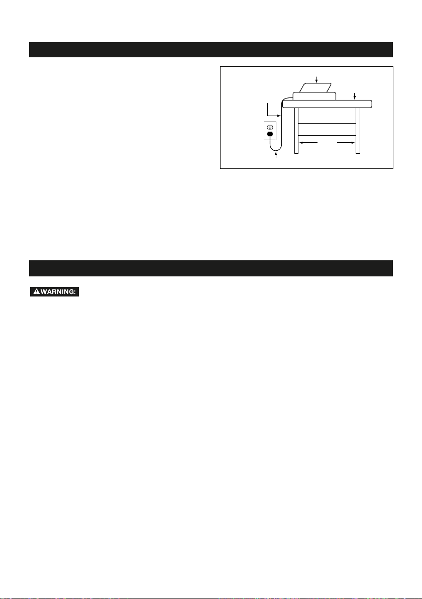
÷ 7KLV WRRO LV LQWHQGHG IRU XVH RQ D FLUFXLW ZLWK D
JURXQGHG RXWOHW % )LJ 7KH WRRO KDV D
JURXQGLQJSOXJ$)LJ
÷ $ WHPSRUDU\ DGDSWHU ' )LJ PD\ EH XVHG WR
FRQQHFW WKLV SOXJ WR D SROH UHFHSWDFOH & )LJ
LI D SURSHUO\ JURXQGHG RXWOHW LV QRW DYDLODEOH
7KH JUHHQFRORUHG WDE H[WHQGLQJ IURP WKH DGDSWHU
PXVW EHFRQQHFWHG WR D SHUPDQHQW JURXQG VXFK
DV D SURSHUO\ JURXQGHG RXWOHW ER[ 7KH WHPSRUDU\
DGDSWHU VKRXOG EH XVHG RQO\ XQWLO D TXDOLILHG
HOHFWULFLDQFDQLQVWDOODSURSHUO\JURXQGHGRXWOHW
÷ *URXQGIDXOW FLUFXLW LQWHUUXSWHU *)&, SURWHFWLRQ
VKRXOG EH SURYLGHG RQ WKH FLUFXLW RU RXWOHW WR EH
XVHGIRUWKHWLOHVDZ5HFHSWDFOHVDUHDOVRDYDLODEOH
KDYLQJ EXLOWLQ *)&, SURWHFWLRQ DQG PD\ EH XVHG
IRUWKLVPHDVXUHRIVDIHW\
7,9:65(3:(-,;@
7KH RSHUDWLRQ RI DQ\ SRZHU WRRO FDQ
UHVXOW LQ IRUHLJQ REMHFWV EHLQJ WKURZQ
LQWR\RXUH\HVZKLFKFDQUHVXOWLQVHYHUHH\HGDPDJH
%HIRUH EHJLQQLQJ SRZHUWRRO RSHUDWLRQ DOZD\V ZHDU
VDIHW\JRJJOHVRUVDIHW\JODVVHVZLWKVLGHVKLHOGVDQG
DIXOOIDFHVKLHOGZKHQQHHGHG:HUHFRPPHQG:LGH
9LVLRQ6DIHW\ 0DVN IRU XVH RYHUH\HJODVVHVRU
VWDQGDUG VDIHW\ JODVVHV ZLWK VKLHOGV $OZD\V XVH H\H
SURWHFWLRQZKLFKLVPDUNHGWRFRPSO\ZLWK$16,=
÷ :;(@(3,9;>(;*/ >/(; @6< (9, +605.
HUK <:, *64465 :,5:,ZKHQ RSHUDWLQJ D
SRZHUWRRO
÷ +6 56;XVH WKH WRRO ZKLOH WLUHG RU XQGHU WKH
LQIOXHQFHRIGUXJVDOFRKRORUPHGLFDWLRQ
÷ >,(9 7967,9 (77(9,3'R QRW ZHDU ORRVH
FORWKLQJJORYHVQHFNWLHVULQJVEUDFHOHWVRURWKHU
MHZHOU\
÷ 3XOOEDFNDQGVHFXUHORQJKDLU1RQVOLSIRRWZHDULV
UHFRPPHQGHG
÷ 2,,7 @6<9 /(09 *36;/05. (5+ /(5+:
(>(@-96446=05.7(9;:
÷ 9,46=, (+1<:;05. 2,@: 69 >9,5*/,:
)RUP D KDELW RI FKHFNLQJ WR VHH WKDW NH\V DQG
DGMXVWLQJ ZUHQFKHV DUH UHPRYHG IURP WKH WRRO
EHIRUHWXUQLQJLWRQ
÷ (3>(@: <:, :(-,;@ .3(::,:(YHU\GD\
JODVVHVPD\KDYHLPSDFWUHVLVWDQWOHQVHVEXWWKH\
DUH127VDIHW\JODVVHV
÷ <:, ( +<:; 69 -(*, 4(:2LI WKH RSHUDWLRQ LV
GXVW\
÷ >,(9 /,(905. 796;,*;065WR KHOS SUHYHQW
KHDULQJORVV
÷ 5,=,9 ;6<*/ ;/, 705: 6- ;/, ,3,*;90*(3
73<.ZKLOHLQVHUWLQJLWLQWR RUUHPRYLQJLW IURPDQ
HOHFWULFDOVRFNHW
÷ 5,=,9 :;(5+ 65 ;6636HULRXV LQMXU\ FRXOG
RFFXU LI WKH WRRO LV WLSSHG RU LI WKH FXWWLQJ WRRO LV
XQLQWHQWLRQDOO\FRQWDFWHG
(+(7;,9
.96<5+05.
4,(5:
*<99,5;
*(99@05.
7965.:
.96<5+05.705
365.,:;6-;/,
)3(+,:
.96<5+,+
6<;3,;)6?
D
C
B
A
-0.<9,
5
GENERAL SAFETY RULES
continued on page 6
TOOL SAFETY
sKEEP ALL GUARDS IN PLACE and in working
order.
sAVOID ACCIDENTAL STARTING. Be sure the
switch is in the “Off” position before plugging the
tool into an electrical outlet.
sDO NOT CARRY TOOLS WITH YOUR FINGER ON
THE SWITCH.
sDO NOT OVER REACH.Keep proper footing and
balance at all times.
sDO NOT FORCE THE TOOL. Use the correct tool
and cutting wheel for your application. The correct
tool and cutting wheel will do the job better and
more safely when used at the rate for which it is
designed.
sDO NOT USE TOOL IF THE SWITCH DOES NOT
TURN IT “ON” OR “OFF.” Any tool that cannot be
controlled with the switch is dangerous and must
be repaired.
sDISCONNECT THE TOOL before servicing, when
changing accessories (such as cutting wheels), or
storing the tool.
sSTORE IDLE TOOLS OUT OF THE REACH OF
CHILDREN and other untrained people.
sNEVER LEAVE THE TOOL RUNNING
UNATTENDED; TURN THE POWER OFF. Don’t
leave the tool until it comes to a complete stop.
sALWAYS MAINTAIN TOOLS WITH CARE.
Keep cutting tools sharp and clean. Properly
maintained tools with sharp cutting edges are less
likely to bind and are easier to control. Follow
all instructions for lubricating and changing
accessories.
sCHECK FOR DAMAGED PARTS. Before further
use of the tool, a guard or other part that is
damaged should be carefully checked to determine
that it will operate properly and perform its
intended function. Check for alignment of moving
parts, binding of moving parts, mounting, and any
other conditions that may affect its operation. A
guard, cutting wheel or other part that is damaged
should be properly repaired or replaced.
sUSE RECOMMENDED ACCESSORIES. Consult
the product manual for recommended accessories.
The use of improper accessories may increase the
risk of personal injury.
SERVICE SAFETY
sIf any part of this wet-tile/stone saw is missing or
should break, bend, or fail in any way; or should
any electrical component fail to perform properly:
ALWAYS shut off the power switch and remove
the plug from the power source, and have the
missing, damaged, or failed part replaced BEFORE
resuming operation.
sWhen servicing a tool, ALWAYS use only identical
replacement parts. Follow instructions in the
Maintenance Section of this manual. Use of
unauthorized parts or failure to follow Maintenance
Instructions may create a risk of electric shock or
injury.
SPECIFIC SAFETY INSTRUCTIONS FOR WET TILE/STONE SAW
BE SURE to read and understand all
instructions in this manual before
using this Wet Tile/ Stone Saw. Failure to follow all
instructions may result in electric shock, fire and/or
serious personal injury
To reduce the risk of mistakes that
could cause serious, permanent
injury, do not plug the tile saw into an electrical
receptacle until the following steps have been
satisfactorily completed:
sCompletely assemble the saw (See “Assembly”
section).
sLearn the use and function of the ON-OFF switch,
cutting wheel guard, overload protector, spindle
lock, depth-stop-adjustment knob, depth-
adjustment knob, bevel-cut-adjustment knob,
universal guide etc. (See “Getting to Know Your Tile
Saw” section).
sReview and understand all safety instructions and
operating procedures in this manual.
sReview the maintenance methods for this saw (See
“Maintaining Your Saw” section).
sNever put your fingers or hands in the path of the
saw cutting wheel or other cutting tool.
sNever reach behind the cutting tool with either hand
for any reason. Do not reach behind the cutting
wheel to hold down the work piece, support the
work piece, remove scraps, or for any other reason.
sNever use a hand position where a sudden slip
could cause the fingers or the hand to move into a
saw cutting wheel.
sFind and read all the warning labels found on the
tool.
The labels on your tool may include the
following symbols.
V–Volts
A– Amperes
Hz –Hertz
W– Watts
min – Minutes
~– Alternating current
n0– No-load speed
RPM – Revolutions or Strokes per minute
– Indicates danger, warning or caution. It
means attention! Your safety is involved.
4 5