Reliable Equipment LR-CS-82 Manual

1
DISTRIBDISTRIB
DISTRIBDISTRIB
DISTRIBUTED BYUTED BY
UTED BYUTED BY
UTED BY
WW
WW
WARNINGARNING
ARNINGARNING
ARNING
All information found in this guide
must be read and understood before
use or testing of this tool.
Failure to read and understand these warnings
and safe handling instructions could result in
severe personal injury and or death.
LR-CS-82 Manual 05-09
OPERAOPERA
OPERAOPERA
OPERATT
TT
TORS’ORS’
ORS’ORS’
ORS’ GUIDEGUIDE
GUIDEGUIDE
GUIDE
LR-CS-82LR-CS-82
LR-CS-82LR-CS-82
LR-CS-82
HYDRAHYDRA
HYDRAHYDRA
HYDRAULIC LULIC L
ULIC LULIC L
ULIC LONG REAONG REA
ONG REAONG REA
ONG REACHCH
CHCH
CH
CIRCIR
CIRCIR
CIRCULAR SACULAR SA
CULAR SACULAR SA
CULAR SAWW
WW
W
The powerful hydraulic drive motor can easily cut brush and branches
up to 3.5 inches in a single pass.
The quick stop trigger reduces blade coast time for increased safety.
The dielectric property of the fiberglass extension tube will reduce
the chance of electric shock.
For cutting and trimming of limbs and branches from the ground
or an aerial bucket that a standard chainsaw could not reach.
ELECTROCUTION
HAZARD
The user should be properly
trained in the correct procedures
required for work on or around
electrical lines.
REL-SM

2
TABLE OF CONTENTS
Registration .................................. 2
Saw Description ........................2-3
Safety Instructions .................. 4-11
SPECIFICATIONS
General...................................... 3, 8
Connections and Hoses .............. 9
Pre-Operation ............................. 10
Spool Selector (Fig. 1)................ 10
Operation of Saw........................ 11
MAINTENANCE
General........................................ 12
Troubleshooting ......................... 13
DESCRIPTION
The long reach circular saw is intended for safely cutting and trimming trees which
are out of reach of the ordinary chain saw. The powerful hydraulic drive motor can
easily make cuts of 3.5 inche sin depth from the ground or an aerial bucket. With an
overall length of 82 inches, the operator is easily able to reach limbs not possible
with a standard chain saw.
The dielectric property of the fiberglass extension tube will reduce the chance of
electric shock when used near an energized electric line. Other features include a trigger
guard to prevent accidental movement of the blade, and a rubber collar hand stop.
A quick set spool can be turned 180 degrees for closed center/open center operations.
UPON RECEIPT OF THIS TOOL, COMPLETE THE REGISTRATION BELOW.
SERIAL NUMBER
DATE OF PURCHASE
DEALER NAME
PARTS LISTS
Major Components (Fig. 2) ........ 14
Head Assembly (Fig.3) ............... 15
Handle (Fig. 4)............................. 16
REPAIR INSTRUCTIONS
Blade & Motor Disassembly...... 17
Blade Installation........................ 18
Valve/Handle Disassembly ....... .18
Tube Disassembly / Assembly... 19
This symbol indicates items
of extreme importance. Safety
of user and others may be in
jeopardy if these instructions
are not read and understood.

3
NEW LR-CS-82LR-CS-82
LR-CS-82LR-CS-82
LR-CS-82
HYDRAULIC LONG REACH CIRCULAR SAW
Reliable’s LR-Series long reach saws are intended for safely
trimming trees from the ground or an aerial bucket. With an
overall length of 82 inches, the operator may easily reach areas
not possible with a standard chain saw. The offset head
provides a flush cut, from a comfortable stance, reducing
operator fatigue and strain.
The powerful hydraulic drive motor can easily cut branches up to
3.5 inches in a single pass. The quick stop trigger reduces blade
coast time for increased safety. The dielectric property of the
fiberglass extension tube will reduce the chance of electric shock.
FEATURES:
Insulated fiberglass extension tube - reduces risk of
electrical shock when used near an energized line.
Quick Stop System - reduces blade coast time.
Trigger Guard - prevents accidental blade activation.
Quick Set Spool - may be turned 180Ofor open center or
closed center operation.
9” Blade - Allows a 3.5 inch cutting depth.
Rubber Collar Hand Stop.
SPECIFICATIONS:
Weight: 9.3 lbs. Lenght: 82 inches
Flow Range: 5-8 gpm
Blade Speed: 4,800 RPM @ 6 gpm
Operating Pressure: 1,000-2,000 psi
Pressure & Return Port Thread: # 6 SAE & # 8 SAE
Blade Diameter: 9 inches
Blade Thickness: .1/16 inch
Arbor: 0.635” x 0.878 inch
Blade Operating RPM: 5,400 (minimum)
Meets OSHA
1910.269
RELIABLE EQUIPMENT & SERVICE CO., INC.
92 STEAMWHISTLE DRIVE • IVYLAND, PA 18974
TOLL FREE:
800-966-3530
• FAX:
215-357-9193
Visit us on the web at www.Reliable-Equip.com

4
WARNING
BEFORE USING CIRCULAR SAW, READ THE WARNINGS
and the recommended practices described in this manual.
Failure by the operator to read and fully understand these
warnings will leave this person unqualified to use and
operate this tool. Property damage, severe personal injury,
and/or death could result by not following these warnings.
Eye
Protection
These warnings will appear in appropriate locations when they are pertinent to the
particular subject being shown. Read each one carefully and follow them strictly.
WARNING
Always wear eye protection to avoid
injury from flying debris or hydraulic
oil leaks. Failure to do so can result
in serious personal injury.
Hard Hat
WARNING
Alwaysweara hard hattoavoid injury
from debris. Failure to do so can
result in serious personal injury.
Hearing
Protection
WARNING
Always wear hearing protection, to
avoid hearing loss due to long term
exposure to high noise levels.
Foot
Protection
WARNING
Always wear foot protection.
Failure to do so can result in serious
personal injury.
Dust Mask
WARNING
Some timbers may produce irritants.
Failure to observe this warning
may result in serious health issues
and/or breathing difficulty.
WARNING
Protective
Gloves
Always wear hand protection, to
avoid cuts, burns, pinching and
exposure irritants.

5
Jamming
Jamming or pinching will occur when the wood being cut
closes in on top of the blade. This action results in pushback
or a kickback, usually very fast with strong force toward
the operator. Be careful and be aware of what causes this
set of circumstances, so the operator can do everything
possible to avoid them.
WARNING
Safety
DO NOT attempt to make any changes to any of the component
parts or accessories when connected to the power source.
DO NOT adjust, inspect, or clean tool while the tool is connected
to the power source. The tool could accidentally start up
and cause serious injury.
DO NOT lock the trigger in the On Position. In an emergency, it is impossible
to shut down the tool. Serious damage or injury could occur during the
time required to stop the tool.
DO NOT alter or remove the safety latch attached to the trigger. This latch is
designed to prevent accidental movement of the trigger, which could cause
the chain to start up and cause severe personal injury or property damage.
DO wear protective gloves when handling or adjusting the saw chain. The saw can
and will cause damage to the hands without gloves either running or stopped.
Failure to follow these warnings can result in serious injury and/or death.
WARNING
Tip Contact
Accidentally bumping of an object with the tip of the saw
may cause a rapid movement of the assembly up and back
towards the operator, with possible injury to the operator
or damage to the surrounding objects.
Worn or Damaged Blade
DO NOT operate this tool with a worn or damaged blade.
A worn, damaged, or dull blade will increase the likelihood
of kickback or pushback.
WARNING
WARNING

6
WARNING
Oil Injection Injury
Hydraulic oil or fluid under the skin is a serious injury.
Oil under pressure can penetrate the skin and may cause
dismemberment or loss of life. Seek medical assistance
immediately if such an injury should occur.
Always wear safety gloves and eye protection when operating or handling.
DO NOT use fingers or hands to attempt to locate a leak.
DO NOT Handle Hoses or Couplers while the hydraulic system is pressurized.
NEVER open or service the system before completely depressurizing.
Electrical Shock Hazard
Use only certified nonconductive hoses and fittings. Always
wear and use the necessary clothing, equipment and safety
practices to protect against electrical shock. Failure to
follow these rules can result in serious personal injury.
WARNING
Make certain the fiberglass extension tube is free from moisture, oil, and
grease. The accumulation of any or all of the above-mentioned materials
will reduce the insulating properties of the fiberglass extension tube.
WARNING
General Safety
Ensure that all fellow employees and bystanders are clear and
protected from possible injury caused by this tool or the
operations being performed. Persons in close proximity could
be injured and property damaged if the tool were to malfunction.
This tool should always be used within the limits and purposes
stated by the product manufacturer. Abuse or usage over and
above the manufacturers’ intended purposes could cause
damage to the tool and severe injury to the operator.
Burn Hazard
Saw body and blade as well as other components will be hot
during and after use. Use care when handling this tool.
Hot surfaces may cause serious burns.
Failure to observe this warning may result in serious injury.
WARNING

7
Burn Hazard
Do Not connect or disconnect tool, hoses or fittings while
power source is running or while hydraulic fluid is hot.
Hot hydraulic fluid may cause serious burns.
Failure to observe this warning could result in serious injury.
WARNING
Safe Operation & Care
USE THIS TOOL FOR CUTTING WOOD ONLY, Any other use
can result in injury or property damage.
INSPECT TOOL BEFORE USE. Replace any worn, damaged
or missing parts. A damaged or improperly assembled tool
may malfunction, injuring operator and/or nearby personnel.
INSPECT HYDRAULIC HOSES AND COUPLINGS before each
use. Repair or replace if any cracking, leakage, wear or
damage is is found. Worn or damaged hoses may fail
resulting in personal injury or property damage.
CLEAR WORK AREA of all bystanders and unnecessary
personnel before operating this tool. Falling or flying debris
could cause serious injury or death.
Failure to observe this warning could result in serious injury.
CAUTION
Safe Handling
HYDRAULIC FLUID MAYCAUSE SKIN IRRITATION.
Handle hydraulic tools and hoses with care to prevent
hydraulic fluid from making contact with skin.
IN THE EVENT OF ACCIDENTAL SKIN CONTACT with hydraulic
fluid, immediately wash the area thoroughly.
Failure to observe this warning could result in serious injury.
CAUTION
Vibration Hazard
Apply just enough pressure to make the cut. Applying
excess pressure to the tool may cause operator discomfort
or temporary numbness.
Failure to observe this warning could result in serious injury.
CAUTION

8
TOOL SPECIFICATIONS
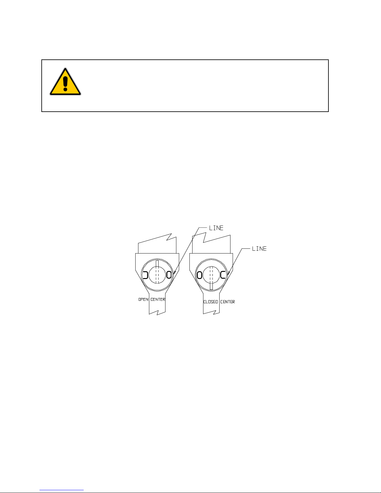
System...........................................................................Open-Center or Closed Center
Overall Length .................................................................................82 inches (202.28 cm)
Handle Width........................................................................................ 7.5 in. (19.05 cm)
Opreating Pressure (Min. - Max.)............ 1,750 psi (121 bar) - 2,000 psi (138 bar)
Flow (Minimum).................................................................................... 4 gpm (15.1 l/min)
Flow (Recommended) ......................................................................... 5 gpm (18.9 l/min)
Flow (Maximum)................................................................................... 6 gpm (22.7 l/min)
Pressure Relief (Maximum) .............................................................2,000 psi (138 bar)
Back Pressure (Maximum).................................................................200 psi (13.8 bar)
Pressure & Return Ports .................................................................................... 3/8 NPT
Weight with Blade................................................................................. 9.3 lbs. (4.0 kg)
Blade Diameter (Maximum) ...................................................................9 in. (22.86 cm)
Arbor (DD type)..................................................... 5/8” x 7/8” (15.88 mm x 22.23 mm)
Blade Rating (Minimum)................................................................................. 5,400 rpm
Cutting Depth........................................................................................... 3.5 in. (89 mm)
HYDRAULIC FLUIDS
All hydraulic fluids that meet these listed specifications or the listed HTMA
specifications may be used for this tool.
@ 100OF (38OC) ............................................................... 140 TO 225 S.U.S.
@ 210OF (99OC) ............................................................ 40 S.U.S. (minimum)
FLASH POINT ........................................................ 340OF min. (170O C min.)
POUR POINT..... ..................................................... -30OF min. (-34OC min.)
These specifications must be strictly adhered to for this tool to function
properly. Any deviation can cause tool damage, severe injury or death.
Use only factory specified parts when repairing and/or replacing.
Severe tool damage or personal injury may occur with non-specified parts.
Always use appropriate blades meeting applicable industrial safety
specifications for the use intended by the manufacturer.
WARNING
Blade must be installed to rotate in the correct direction. Follow the blade manufacturer’s
instructions and refer to the illustration later in this manual.
Inspect blade for wear or damage before installing and before each use. A damaged
blade may break causing a hazard for the operator, other personnel and/or bystanders.
Failure to heed these warnings could result in severe bodily injury or death.

9
HOSES AND FITTINGS
There exists the potential for shock in using anything other
than certified nonconductive hoses and hydraulic oil with
dielectric properties, when using system components near
energized electrical lines. Failure to recognize these conditions
could cause electrocution.
Hoses and fittings used with this tool must comply with S.A.E. J1273 which covers
recommended practice for selection, installation, and maintenance of hose and hose
assemblies. The correct hoses and fittings are available from your supplier.
WARNING: Failure to comply with these warnings could result in severe bodily injury.
WARNING
UNIT/HOSE CONNECTIONSUNIT/HOSE CONNECTIONS
UNIT/HOSE CONNECTIONS
ALWAYS SHUT OFF pump/power source before connecting or
disconnecting system components. ALWAYS DEPRESSURIZE
hydraulic system before disconnecting this unit or any of the
systems components.
ALWAYS TIGHTEN couplings completely. Loose or improperly
tightened couplings will not allow fluid to pass through the hose
creating a blockage in the supply or return line.
WARNING
HOSE INSTALLATION
Care must be taken to assure the correct connection of the
hoses to the pressure and return ports. If the hoses are incor-
rectly connected, the tool will run in reverse. This will damage
the tool and create dangerous conditions for the operator.
Always inspect hoses and connectors before using this tool
each time before using. Replace or repair if any leakage is
evident. Leakage is a sign of deterioration in component parts.
Worn or leaking parts must be repaired or replaced, or injury
and severe damage could result.
CAUTION

10
PRE-OPERAPRE-OPERA
PRE-OPERAPRE-OPERA
PRE-OPERATION OF SATION OF SA
TION OF SATION OF SA
TION OF SAWW
WW
W
Before attempting to connect, run, or use the saw, inspect all parts an sub-assemblies,
including hoses, couplings, blade assembly, cleanliness of the fiberglass extension,
trigger latch, freely moving trigger, and the condition of the rubber behind the trigger.
Worn or damaged parts can cause a malfunction during operation and should be replaced.
Inspect the saw blade for damage. The saw will not function properly with a worn (Dull)
or damaged blade. Look for bending, cracking, wear, or any damage to the blade assembly.
A worn or damaged blade could allow pinching, cause kickback, or break creating flying
debris that could result in serious injury to the operator, nearby personnel or bystanders.
Setsaw toOpenor Closed Center, accordingto which systemthe power supplypumpprovides
It is important to know which type of power system is supplying the saw so that the
saw can be properly set.
Setting Spool Selector for Open Center/Closed Center System
Set the Hand Stop approximately 36” from the handle. This should be a comfortable
position for the average person.
Wear all safety items required and make sure that the working area is clear of obstructions.
Ensure all personnel and bystanders are well outside the danger zone.
All of these items are crucial to the safe operating procedure of the saw.
Ensure power source is OFF, and hydraulic flow is lever is turned OFF.
Connect Saw as described on page 9.
Turn ON hydraulic source and flow control lever. (refer to specifications on page 8)
Allow the power source to run for a few minutes to warm the hydraulic fluid.
Operate newly mounted blades on saw for approximately one minute to ensure proper
blade application before cutting material.
DO NOT connect hoses or fittings to this unit before completing
all of the instructions in this section.
Ensure power source is OFF, and hydraulic flow is lever is turned OFF.
Failure to comply with this warning can result in severe injury or death.
WARNING
FIGURE 1

11
OPERATION
Hold the fiberglass tube extension in one hand and the handle in the other hand.
After positioning the saw in the cutting area, move the trigger safety latch to a forward
position, allowing the trigger to be depressed.
Depress the trigger slowly and allow the blade to start rotating.
When at full speed, feed the saw into the material with constant pressure.
Twisting, jamming or forcing the saw while cutting can cause problems such as kickback,
jamming, pulling, or stalling within the cut. This can cause failure and damage to the saw,
and/or seriously injure the operator.
Allow the blade to feed steadily and quickly through the work while applying a pressure
against the cut. NOTE: A slow cut will create excessive heat reducing the life of the blade
When the cut is completed, release the trigger and the saw will stop rotating.
There are a number of safety items that need to be addressed when a novice is using
the tool for the first time. Seek out the supervisor for basic instruction in handling the
tool. Some basic problems are easily overcome by knowing the rules of operation.
Kickback was described earlier in this manual (see page 5). Read again.
Kickback occurs when the blade bumpsor jams the wood. bumping or jamming
the blade will kick the saw up and back toward the operator at lightning speed.
Unintensionally touching the wood with the top side may push the saw out of the
operator’s hands. Both situations can cause serious injury and/or damage to the
operator, nearby persons, and surrounding equipment.
Always be aware of the material being cut. Such things as nails and other hard objects
cancause kickback, flying debris, bladedamage,and/or serious personal injury ordeath.
DO NOT use this saw for cutting or clearing at ground level. If the blade contacts the
ground or other solid object, the operator may lose control of the saw, the blade may
shatter, or flying debris may cause injury to the operator and/or nearby personnel.
Always run the saw at full speed when cutting.
Always stand to the side of the cutting path of the blade.
Never be off balance or overreach while cutting.
Always wear and use proper safety equipment such as hand and eye protection.
Always keep the area clear of obstructions and be aware of potential hazards.
Keep all non-esential personnel out of the danger zone.
Always be alert to shifting or falling tree limbs. Binding and pinching of the blade
may occur and cause difficulty in handling.
To store the saw between operations, find a clear, flat space and lay the saw down.
If the saw is out of use for a period of time, shut off the hydraulic power source
to prevent unnecessary heat and wear to the saw and hoses.
OPERATIONAL SAFETY

12
MAINTENANCE
The service schedule should be followed
as closely as possible. The life, reliability,
and safety of the tool is dependent on
maintenance and will help the tool to remain
productive for a much longer period.
DAILY MAINTENANCE
CLEAN: All surfaces including handle,
trigger, trigger safety latch, fittings, hoses,
motor housing, and especially the fiber-
glass extension tube.
INSPECT: Saw head, blade, handle and
trigger assembly for wear and damage.
Worn or damaged parts can cause a
malfunctionduring operation. An improperly
sharpened blade can cause kickback.
NOTE: A cracked, bent, or damaged blade
should be destroyed. A damaged blade
may break causing a hazard for the operator,
other personnel and/or bystanders.
Visually inspect saw frequently while in
use (NOT RUNNING). Inspect for tool or
blade damage. Inspect for cracked hoses
and leaking fittings.
All the above items must be replaced with
new parts if signs of wear are evident.
CHECK: Fluidlevelofpowersource frequently.
FLUID CONTAMINATION: Cover the ends of
fittings with a rubber dust cap when
disconnected. This will help keep the fluid
from contamination.
MONTHLY MAINTENANCE: Inspect per
Appendix A, SAE Standard J1273, 5/86 for
hose or fitting damage such as wear, cracks
or leakage, replace the necessary parts.
NOTE: Keep Label Set clean and legible.
Replace labels as needed. Part # RL44000
Contact RELIABLE EQUIPMENT, or your
RELIABLE representative if you have any
questions related to the information found
in this manual.
NOTICE
Read and understand Manual
and ALL SAFETY WARNINGS
before operation of this tool.
Failure to observe warnings may
result in property damage and/or
serious personal injury
DANGER
To avoid severe personal injury,
inspect tool before each use.
DO NOT operate with loose,
missing or damaged fasteners.
CAUTION
DO NOT EXCEED
specified flow or pressure
2,000 PSI / 140 BAR
5-7 GPM / 19-26 LPM
Select Closed Center for use
with Closed Center System.
Select Open Center for use
with Open Center System.
See Manual for Instructions
DANGER
The saw blade will continue to
rotate for up to 5 seconds or
more after releasing trigger.
During this coast down time,
any contact with the blade may
result in property damage,
and/or severe personal injury.
After releasing trigger, DO NOT
place saw on the ground, lower
saw into bucket, store saw, or
make contact with personnel,
bucket, boom or vehicle.
Keep personnel, and bystanders
clear of blade, falling limbs,
branches and debris.
USE EXTREME CAUTION
Contact at leak or burst may
cause an oil injection injury.
WARNING
ELECTRICAL SHOCK HAZARD
Use extreme caution when
operating near or around
energized cables.

13
TROUBLE SHOOTING
Will not run
Low hydraulic fluid............................................................ Check fluid level
Incorrect viscosity............................................................. Use recommended fluid
Tool damaged .................................................................. Disassemble and replace damaged parts
Hoses incorrectly connected ............................................ Switch hoses
Dirt in tool......................................................................... Disassemble, clean and repair
Loose parts in tool ............................................................ Check and retighten component parts
Tool runs hot
Low fluid level................................................................... Fill pump reservoir to correct level
Fluid viscosity incorrect .................................................... Use recommended fluid
Fluiddirty ......................................................................... Drain tank, flush, and replace fluid
Parts worn or damaged.................................................... Disassemble and replace worn parts
Fluid supply unit not functioning correctly ......................... Reset to operator manual specs
Tool runs slow
Fluid supply unit not functioning correctly ......................... Reset to operator manual specs.
Fluid not warmed to correct temp..................................... Allow tool a warm-up period
Fluid viscosity too high ..................................................... See recommended viscosity
Worn or damaged parts ................................................... Replace worn parts
Dirt or contaminants in tool............................................... Disassemble and clean
Internal parts worn ........................................................... Replace worn parts
Hydraulic level low............................................................ Fill to level. Check for leaks
Tool is erratic
Hydraulic fluid not warm ................................................... Allow oil to warm up
Dirt or contaminants in tool............................................... Clean and reassemble
Air in system .................................................................... Checkhosesforbreaks,leaks,orlooseconnections
Tool leaks hydraulic fluid
Worn or damaged seals................................................... Disassemble andreplace worn ordamaged seals
Component screws loose................................................. Tighten all fasteners
Tool won’t shut off
Tool trigger spool sticky .................................................... Clean up spool so that spool slides freely
Check for misalignment ................................................... Align trigger linkage
Tool lacks power
Control valve leaking ........................................................ Worn part or seal rings
Tool runs but does not cut
Saw blade is dull .............................................................. Resharpen or replace
Damaged components ..................................................... Replace components
Tool runs backwards
Hoses misconnected........................................................ Reverse the hoses

14
FIGURE 2
Key Part No Description Qty.
1* R44001BCM Head Assembly 1
2 R44012 Outer Tube 1
3 R44014 Handle Body 1
4 13422 Grommet 1
5 R44013 Inner Tube 2
6 13425 Rubber Straps (O-Ring) 4
7 13416 Rear Tube Support 1
8* 13447 Internal O-Ring 4
9 13415 Front Tube Support 1
10 R44006 Hanger Bracket 1
11 13129 Lock Washer 5
12 13497 Hex Bolt 5
13 RL44000 Label Set 1
MAJOR
COMPONENTS
PARTS LIST
1
12
11
89
65
2
4
6
6
12
67
8
11
3
1
12
10

15
Key Part No Description Qty.
1 34356 Blade 1
2 44001B Head with Bearings 1
3 13106 Motor Cap with Bearings 1
4 R44002 Drive Shaft 1
5 13140 Idler Shaft 1
6 13435 Needle Bearing 2
7 12875 11 Tooth Gear 1
8 13436 Motor Gasket 1
9* 13439 O-Ring 1
10 13427 Woodruff Key 1
11 13411 Sealed Bearing 1
12 13434 Snap Ring, Bearing 1
13 R44005 Locating Washer 2
14 R44007 Washer 2
15 R44004 Split Nut 2
16 12795 Drive Pin 2
17 13128 Motor Head Screws 2
18 13438 1/4” Lockwasher 2
1
2
34
5
67
89
10 11
12
13 14 15
16
18
17
FIGURE 3
HEAD ASSEMBLY PARTS LIST

16
Key Part No Description Qty.
13402CHA Complete Handle Assy. 1
1 13421 OC/CC Knob 1
2* 13423 Snap Ring 2
3* 13424 Spool Retainer Washer 2
4* 13414 O-Ring 1
5 13420 Spool 1
6 13402 Handle Body 1
7 13428 Spool Spring 1
8 13445A Spring Pin 1
9* 13417 O-Ring, Internal 1
10 13490 Trigger with safety 1
11 13441 10-32 Screw 3
12 13430 Trigger Pin 1
13 13457 Snap Ring 2
14 13432 Trigger Guard 1
HANDLE
PARTSLIST
FIGURE 4

17
Before any disassembly, disconnect hoses from the saw!
Any residual pressure within the unit can and will spray at high
velocity, injuring the person doing the disassembly.
Hot or pressurized hydraulic fluid will cause serious injury to the body!
Accidental movement of the blade can cause serious injury,
dismemberment of a hand, finger or any other part of the body.
WARNING
Complete disassembly is not recommended. Return the unit to an authorized dealer
for total disassembly and/or repair.
All maintenance or disassembly should take place on a flat, clean work surface covered
with towels or wipers so as to have a clean space for the disassembled parts.
Inspect each part during disassembly for damage wear, scratches, and cuts.
Discard the worn or damaged parts and replace with new parts.
O-rings are sensitive to sharp edges. Inspect closely for cuts or damage. A small cut
will cause a leak. When assembling or disassembling O-rings, use hydraulic fluid as
a lubricant to help disassembly or installation.
DISASSEMBLY
BLADE AND MOTOR ASSEMBLY
Refer to Figure 3, Page 15
1. Remove the Split Nut (15) by turning the upper nut in the
clockwise direction while securing the lower nut and shaft
in place.
2. Remove lower nut by turning in the clockwise direction.
3. Remove the Blade Washer (14).
4. Remove the Blade (1) from the Locating Washer (13).
5. Lift Locating Washer (13) Off of Shaft (4)
Motor disassembly: Remove 8 screws (18) and lift motor cap (17) off. Remove motor
gears (14), gasket (16) and idler shaft (15). Bearings (12) and (13) should not need
to be removed unless extreme wear has occurred. Bearing replacement would be a
factory function only.
Contact RELIABLE EQUIPMENT at 800-966-3530 if you have any
questions related to the instructional information found in this manual.

18
BLADE INSTALLATION (Refer to Figure 3, Page 15)
VALVE/HANDLE DISASSEMBLY
(Refer to Figure 4, Page 16)
Remove the three button head screws (13) holding the trigger guard to the valve
body. Remove one snap ring (15) from the pin (14), holding the trigger to the valve
body, and remove pin. Before removing the control knob (1), mark the relative position
to the spool (5). Remove pin (6) from spool (5). Remove retaining ring (2) and remove
knob (1) from the spool (5). Remove washer (3) and spring (8). If there is a problem
with the O-ring (11), remove the bottom retaining ring (2), the bottom washer and
with an O-ring removal tool, remove O-ring (11) for inspection.
Blade must be installed to rotate in the correct direction. Follow the blade manufacturer’s
instructions and refer to the illustration later in this manual.
Inspect blade for wear or damage before installing and before each use. A damaged
blade may break causing a hazard for the operator, other personnel and/or bystanders.
Failure to heed these warnings could result in severe bodily injury or death.
Inspect all parts for wear or damage before replacing the blade. Replace as needed.
Inspect blade for wear, bending, cracking or damage. (Discard or destroy damage blades.)
1. Install the Blade (1) onto the Locating Washer (13).
2. Slide the Blade Washer (14).
3. Install lower portion of the Split Nut (15) by turning in the
counterclockwise direction.
4. Install the Split Nut (15) onto shaft and lower nut by
turning the upper nut in the counterclockwise direction
while securing the lower nut and shaft in place.
These specifications must be strictly adhered to for this tool to function
properly. Any deviation can cause tool damage, severe injury or death.
Use only factory specified parts when repairing and/or replacing.
Severe tool damage or personal injury may occur with non-specified parts.
Always use appropriate blades meeting applicable industrial safety
specifications for the use intended by the manufacturer.
WARNING
Contact RELIABLE EQUIPMENT at 800-966-3530 if you have any
questions related to the instructional information found in this manual.

19
TUBE DISASSEMBLY (Refer to Figure 2, Page 14)
Removal of Tube Assembly from Valve
Remove two screws (9) from valve body. Gently slide outer tube (3) from valve (10).
Removal of Tube Assembly from Motor Housing - Remove three bolts and lockwashers
(12) from motor housing. Gently slide outer tube (3) away from motor housing.
Removal of Inner Tubes (5 and 6) from Outer Tube (3). Pull inner tubes from outer tube.
Three O-rings (7) have been twisted into a figure 8 and slid over the two-tube assembly
to hold the two tubes together and in alignment. Make sure that they are aligned properly.
The inner tubes as depicted in Fig. 4 show the relative position of the pressure and
return tube to the other components. Be sure that the inner tube assembly is in the
position shown relative to the valve and the motor head.
ASSEMBLE TUBES (See Figure 2, Page 14)
Tie the two inner tubes together with the three O-rings (7) twisted in a figure 8
configuration. The pressure tube (6) is marked with blue ink on each end. The return
tube (5) has no marking. As shown in Fig. 4, the pressure tube closest to the bottom
of the page. The return tube is shown above the pressure tube. Tubes must be fitted
into the Rear Tube Support (8) with the O-ring around its end (shown on the right.)
The outer tube support can be inserted after placing it over the inner tubes and aligning
it with the three holes in the head casting. Internal O-rings (1) should be replaced
after disassembly. Remove and replace. Slide inner tubes (5 and 6) into their proper
sockets with extreme care. The sockets can be seen in a cutaway section in Fig. 7.
Be sure that the ends of the inner tubes are clean and free of burrs and tears so as
not cut or scratch the O-rings. Install the three oval head screws (11) and two button
head screws (9).
ASSEMBLE VALVE/HANDLE BODY
(See Figure 4, Page 16)
Install O-ring (11) in the groove near the bottom of the Spool Cavity, followed by
Washer (3) and Retaining Ring (2).
Install O-ring (4) on Spool (5) being careful not to cut the ring when passing over
sharp corners. Lubricate the Spool and slide it gently in the Valve Body. Install the
Spring (8) followed by the Washer (3) and the Retaining Ring (2).
Install Knob (1) and Pin (6) in the Spool (5). Care must be taken to achieve the
correct rotational position of the OC/CC markings in relation to certain features of
the spool (5). There is a small flat on the spool where the Knob goes on. When this
flat is facing up, the C on the back of the Knob (for closed center) is facing right.
Install the Trigger Assembly with the Pin (14) and the Snap Rings (15), followed by
the Trigger Guard (16) using the Button Head Screws (13).

20
92 Steamwhistle Drive Ivyland, PA 18974
Phone: 800-966-3530 Fax: 215-357-9193
Visit us on the web at www.Reliable-Equip.com
If you have any questions regarding the information
in this manual please contact RELIABLE EQUIPMENT
at the address, phone or fax numbers shown below.
WARNING
OperOper
OperOper
Operaa
aa
ation/Saftion/Saf
tion/Saftion/Saf
tion/Safetyety
etyety
ety methods may vary in
accordance with the working guidelines
established by each Utility or Contractor.
For your own safety, ensure that you fully
comply with all safe operation guidelines
required by your employer.
Date Parts or Service Required
MAINTENANCE RECORD
Table of contents
Other Reliable Equipment Saw manuals
Popular Saw manuals by other brands

Cosen
Cosen MH-350DM instruction manual

Ozito
Ozito CMS-210 instruction manual

Scheppach
Scheppach Structo 5.0 Translation from the original instruction manual

Powermatic
Powermatic 66 Maintenance instructions and parts list

Diamond Products
Diamond Products CC1113H Operator's manual

RADLEY
RADLEY 1345-000 owner's manual