Laird LTM-4x4HDSDI User manual

USER MANUAL
Model:
LTM-4x4HDSDI
4x4 HD-SDI / SDI Router

Contents
i
Contents
1
Introduction 1
2
Getting Started 1
3
Overview 1
4
Your LTM-4x4HDSDI 4x4 HD-SDI / SDI Router 2
5
Installing on a Rack 5
6
Connecting Your LTM-4x4HDSDI 4x4 HD-SDI / SDI Router 6
6.1
Dipswitch Settings 8
6.1.1
Setting the Machine # Dipswitches 8
6.2
Controlling via RS-232 (for example, using a PC) 9
6.3
Controlling via the RS-485 Port 9
6.4
Controlling via ETHERNET 10
6.4.1
Connecting the ETHERNET Port directly to a PC (Crossover Cable) 10
6.4.2
Connecting the ETHERNET Port via a Network Hub (Straight-Through Cable) 12
6.4.3
Control Configuration via the Ethernet Port 12
6.5
Controlling via the REMOTE Connector 12
7
Operating the LTM-4x4HDSDI 13
7.1
Switching OUT-IN Combinations 13
7.2
Confirming Settings 13
7.2.1
Toggling between the AT ONCE and CONFIRM Modes 14
7.2.2
Confirming a Switching Action 14
7.3
Storing/Recalling Input/Output Configurations 15
7.3.1
Storing an Input/Output Configuration 15
7.3.2
Recalling an Input/Output Configuration 15
7.4
Locking the Front Panel 15
8
Technical Specifications 16
9
Table of Hex Codes for Serial Communication 16
10
Protocol 2000 17
Figures
Figure 1: LTM-4x4HDSDI 4x4 HD-SDI / SDI Router 3
Figure 2: Connecting the LTM-4x4HDSDI 4x4 HD-SDI / SDI Router 7
Figure 3: LTM-4x4HDSDI SETUP Dipswitches 8
Figure 4: Connecting a PC without using a Null-modem Adapter 9
Figure 5: RJ-45 PINOUT 10
Figure 6: Local Area Connection Properties Window 11
Figure 7: Internet Protocol (TCP/IP) Properties Window 11
Figure 8: Using the REMOTE Connector 12

Contents
ii
Tables
Table 1: Front Panel LTM-4x4HDSDI 4x4 HD-SDI / SDI Router 4
Table 2: Rear Panel LTM-4x4HDSDI 4x4 HD-SDI / SDI Router 4
Table 3: Machine # Dipswitch Settings 8
Table 4: Crossover Cable RJ-45 PINOUT 10
Table 5: Straight-through Cable RJ-45 PINOUT 12
Table 6: Technical Specifications of the LTM-4x4HDSDI 4x4 HD-SDI / SDI Router 16
Table 7: LTM-4x4HDSDI Hex Codes for Switching via RS-232/RS-485 16
Table 8: Protocol Definitions 17
Table 9: Instruction Codes for Protocol 2000 18

Introduction
1
1 Introduction
Congratulations on purchasing your LTM-4x4HDSDI 4x4 HD-SDI / SDI
Router. This product is ideal for:
Professional broadcasting and production studios
Presentation applications
The package includes the following items:
LTM-4x4HDSDI 4x4 HD-SDI / SDI Router
Power cord, Null-modem adapter and this user manual
2 Getting Started
We recommend that you:
Unpack the equipment carefully and save the original box and
packaging materials for possible future shipment
Review the contents of this user manual
3 Overview
The LTM-4x4HDSDI is a true 4x4 matrix switcher for standard definition /
high definition SDI signals that lets you simultaneously route any of the four
inputs to any or all of the four outputs. In particular, the LTM-4x4HDSDI
features:
Input and output signals on BNC connectors
Selector buttons that automatically light up in different colors—red,
when the LTM-4x4HDSDI detects a ‘standard definition’ signal, or
blue, when it detects a ‘high definition’ signal
Reclocking and equalization on each input
Switching according to the Bi-level or Tri-level Genlock input
according to SMPTE RP-168
The storing and recalling of setups
A Take button for the execution of multiple switches all at once
A front panel lock
A 7-segment display

Your LTM-4x4HDSDI 4x4 HD-SDI / SDI Router
2
The LTM-4x4HDSDI, which is housed in a 19" 1U rack mountable
enclosure, and is fed from a 100-240 VAC universal switching power supply,
can be controlled via the:
Front panel buttons
Infra-red remote control transmitter
Remotely, by RS-232 or RS-485 serial commands transmitted by a
touch screen system, PC, or other serial controller
ETHERNET
Remote contact closure for forced operation
To achieve the best performance:
Connect only good quality connection cables, thus avoiding
interference, deterioration in signal quality due to poor matching, and
elevated noise levels (often associated with low quality cables)
Avoid interference from neighboring electrical appliances that may
adversely influence signal quality and position your LTM-4x4HDSDI
away from moisture, excessive sunlight and dust
4 Your LTM-4x4HDSDI 4x4 HD-SDI / SDI Router
Figure 1, Table 1, and Table 2 define the LTM-4x4HDSDI 4x4 HD-SDI /
SDI Router.

Your LTM-4x4HDSDI 4x4 HD-SDI / SDI Router
3
Figure 1: LTM-4x4HDSDI 4x4 HD-SDI / SDI Router

Your LTM-4x4HDSDI 4x4 HD-SDI / SDI Router
4
Table 1: Front Panel LTM-4x4HDSDI 4x4 HD-SDI / SDI Router
# Feature Function
1 IR Receiver The red LED is illuminated when receiving signals from the Infra-red
remote control transmitter
2 POWER Switch Illuminated switch for turning the unit ON or OFF
3 INPUT SELECTOR Buttons Select the input to switch to the output
4 OUTPUT SELECTOR
Buttons
Select the output to which the input is switched
5 TAKE Button Pressing TAKE toggles the mode between the CONFIRM mode
1
and
the AT ONCE mode (user confirmation per action is unnecessary)
6 ALL Button Pressing ALL followed by an INPUT button, connects that input to all
outputs
2
7 OFF Button An OFF-OUT combination disconnects that output from the inputs; an
OFF-ALL combination disconnects all the outputs
8 LOCK Button Disengages the front panel buttons
9 RCL (RECALL) Button Pressing the RCL button and the corresponding INPUT / OUTPUT
key recalls a setup from the non-volatile memory. The stored status
blinks. Pressing a different INPUT / OUTPUT button lets you view
3
another setup. After making your choice, pressing the RCL button
again implements the new status
10
STO (STORE) Button Pressing STO followed by an INPUT / OUTPUT button stores the
current setting
4
11
7-segment Display Displays the selected input switched to the output (marked above
each input)
Table 2: Rear Panel LTM-4x4HDSDI 4x4 HD-SDI / SDI Router
# Feature Function
12
GENLOCK BNC Connector Connect to the Genlock source
13
TERM Button Press to terminate the Genlock source (75) or release for looping
5
14
LOOP BNC Connector Connect to the GENLOCK connector of the next unit in the line
15
INPUT BNC Connectors Connect to the serial digital video sources
16
OUTPUT BNC Connectors Connect to the serial digital video acceptors
17
REMOTE Terminal Block
Connector
Connect to dry contact switches
18
RS-232 DB 9F Port Connects to the PC or the Remote Controller
6
19
RS-485 Detachable
Terminal Block Port
Pin G is for the Ground connection
7
; pins B (-) and A (+) are for RS-485
20
SETUP Dipswitches Dipswitches for setup of the unit
21
ETHERNET Connector Connects to the PC or other Serial Controller through computer networking
22
Power Connector with Fuse AC connector enabling power supply to the unit
1 When in Confirm mode, the TAKE button illuminates
2 For example, press ALL and then Input button # 2 to connect input # 2 to all the outputs
3 Only view, nothing is implemented at this stage
4 For example, press STO and then the Output button # 3 to store in Setup # 3
5 Push in to terminate the input. Release when the input extends to another unit
6 Via a null-modem connection
7 The ground connection is sometimes connected to the shield of the RS-485 cable. In most applications, the ground is not
connected

Installing on a Rack
5
5 Installing on a Rack
This section describes what to do before installing on a rack and how to rack
mount.
Before Installing on a Rack
Before installing on a rack, be sure that the environment is
within the recommended range:
Operating temperature range +5 to +45 Deg. Centigrade
Operating humidity range 5 to 65 % RHL, non-condensing
Storage temperature range -20 to +70 Deg. Centigrade
Storage humidity range 5 to 95% RHL, non-condensing
CAUTION!!
When installing on a 19" rack, avoid hazards by taking care
that:
1
It is located within the recommended environmental
conditions, as the operating ambient temperature of a
closed or multi unit rack assembly may exceed the room
ambient temperature.
2
Once rack mounted, enough air will still flow around the
machine.
3
The machine is placed straight in the correct horizontal
position.
4
You do not overload the circuit(s). When connecting the
machine to the supply circuit, overloading the circuits might
have a detrimental effect on overcurrent protection and
supply wiring. Refer to the appropriate nameplate ratings for
information. For example, for fuse replacement, see the
value printed on the product label.
5
The machine is earthed (grounded) in a reliable way and is
connected only to an electricity socket with grounding. Pay
particular attention to situations where electricity is supplied
indirectly (when the power cord is not plugged directly into the
socket in the wall), for example, when using an extension
cable or a power strip, and that you use only the power cord
that is supplied with the machine.
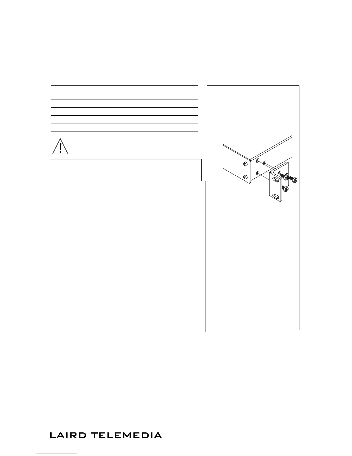
How to Rack Mount
To rack-mount the machine:
1
Attach both ear brackets to the
machine. To do so, remove the
screws from each side of the
machine (3 on each side), and
replace those screws through
the ear brackets.
2
Place the ears of the machine
against the rack rails, and insert
the proper screws (not provided)
through each of the four holes in
the rack ears.
Note that:
In some models, the front panel
may feature built-in rack ears
Detachable rack ears can be
removed for desktop use
Always mount the machine in the
rack before you attach any cables or
connect the machine to the power

Connecting Your LTM-4x4HDSDI 4x4 HD-SDI / SDI Router
6
6 Connecting Your LTM-4x4HDSDI 4x4 HD-SDI / SDI Router
You can use your LTM-4x4HDSDI to switch one of the four standard
definition / high definition SDI inputs to any or all of the four standard
definition / high definition SDI outputs, as the illustration in Figure 2 shows.
To connect the LTM-4x4HDSDI 4x4 HD-SDI / SDI Router, do the
following
1
:
1. Connect up to four SDI sources to the SDI INPUT BNC connectors (for
example, an HD/SD SDI camera to input 1 and an HD video player to input 4).
2. Connect the SDI OUTPUT BNC connectors to up to
2
four SDI acceptors
(for example, output 1 to a Preview monitor, and output 4 to an HD SDI
mixer).
3. Set the dipswitches (see section 6.1).
4. As an option
3
, connect:
A Genlock source to the GENLOCK BNC connector
The LOOP BNC connector to the GENLOCK connector of the next
unit in the line, and release the TERM button for looping
4
5. Connect a PC and/or controller (if required), to the:
RS-232 port (see section 6.2), and/or
RS-485 port (see section 6.3), and/or
ETHERNET connector (see section 6.4)
6. As an option
3
, connect a remote dry contact switch (refer to section 6.5)
7. Connect the power cord
5
.
The example in Figure 2 illustrates how to connect your LTM-4x4HDSDI:
1 Switch OFF the power on each device before connecting it to your LTM-4x4HDSDI. After connecting your
LTM-4x4HDSDI, switch on its power and then switch on the power on each device
2 When only one output is required, connect that output, and leave the other outputs unconnected
3 Not illustrated in Figure 2
4 Pushed in terminates the input. Release when the input extends to another unit
5 We recommend that you use only the power cord that is supplied with this machine

Connecting Your LTM-4x4HDSDI 4x4 HD-SDI / SDI Router
7
Figure 2: Connecting the LTM-4x4HDSDI 4x4 HD-SDI / SDI Router

Connecting Your LTM-4x4HDSDI 4x4 HD-SDI / SDI Router
8
6.1 Dipswitch Settings
By default, all dipswitches are set to OFF.
Figure 3 illustrates the LTM-4x4HDSDI dipswitches:
ON
1 2 3 4
SETUP
Figure 3: LTM-4x4HDSDI SETUP Dipswitches
6.1.1 Setting the Machine # Dipswitches
The Machine # determines the position of a LTM-4x4HDSDI unit,
specifying which LTM-4x4HDSDI unit is being controlled when several
LTM-4x4HDSDI units connect to a PC or serial controller. Set the Machine
# on a LTM-4x4HDSDI unit via SETUP DIPS 1, 2, 3 and 4, according to
Table 3.
When using a standalone LTM-4x4HDSDI unit, set the Machine # to 1.
When connecting more than one LTM-4x4HDSDI unit, set the first machine
(the Master) that is closest to the PC, as Machine # 1 (dipswitches are set to
OFF).
Table 3: Machine # Dipswitch Settings
Mach. # DIP 1 DIP 2 DIP 3 DIP 4
1 OFF OFF OFF OFF
2 OFF OFF OFF ON
3 OFF OFF ON OFF
4 OFF OFF ON ON
5 OFF ON OFF OFF
6 OFF ON OFF ON
7 OFF ON ON OFF
8 OFF ON ON ON

Connecting Your LTM-4x4HDSDI 4x4 HD-SDI / SDI Router
9
6.2 Controlling via RS-232 (for example, using a PC)
To connect a PC to the LTM-4x4HDSDI unit, using the Null-modem adapter
provided with the machine (recommended):
Connect the RS-232 DB9 rear panel port on the LTM-4x4HDSDI
unit to the Null-modem adapter and connect the Null-modem adapter
with a 9 wire flat cable to the RS-232 DB9 port on your PC
To connect a PC to the LTM-4x4HDSDI unit, without using a Null-modem
adapter:
Connect the RS-232 DB9 port on your PC to the RS-232 DB9 rear
panel port on the LTM-4x4HDSDI unit, as Figure 4 illustrates
Figure 4: Connecting a PC without using a Null-modem Adapter
6.3 Controlling via the RS-485 Port
To cascade up to eight individual LTM-4x4HDSDI units, via RS-485 with
control via a Master Programmable Remote Control system, do the following:
1. Connect the “A” (+) and “B” (-) PINS on the RS-485 terminal block port
of the Master Programmable Remote Control system to the “A” (+) and “B” (-)
PINS, respectively, on each of the eight LTM-4x4HDSDI units. (If using
shielded twisted pair cable, the shield is usually connected to the “G”
(Ground) PIN of the first unit).
2. Set the first LTM-4x4HDSDI unit as MACHINE # 1 and the following
seven LTM-4x4HDSDI units as MACHINE # 2 to MACHINE # 8, according
to Table 3.

Connecting Your LTM-4x4HDSDI 4x4 HD-SDI / SDI Router
10
6.4 Controlling via ETHERNET
You can connect the LTM-4x4HDSDI via the Ethernet, using a crossover
cable (see section 6.4.1) for direct connection to the PC or a straight through
cable (see section 6.4.2) for connection via a network hub or network router
1
.
6.4.1 Connecting the ETHERNET Port directly to a PC (Crossover
Cable)
You can connect the Ethernet port of the LTM-4x4HDSDI to the Ethernet
port on your PC, via a standard crossover cable with RJ-45 connectors, as
Table 4 and Figure 5 define.
Table 4: Crossover Cable RJ-45 PINOUT
EIA /TIA 568A
Side 1
EIA /TIA 568B
Side 2
PIN Wire Color PIN Wire Color
1 White-orange 1 White-green
2 Orange 2 Green
3 White-green 3 White-orange
4 Blue 4 Blue
5 White-blue 5 White-blue
6 Green 6 Orange
7 White-brown 7 White-brown
8 Brown 8 Brown
Pair 1 4 and 5 Pair 1 4 and 5
Pair 2 1 and 2 Pair 2 3 and 6
Pair 3 3 and 6 Pair 3 1 and 2
Pair 4 7 and 8
Pair 4 7 and 8
Figure 5: RJ-45 PINOUT
This type of connection is recommended for identification of the factory default
IP Address of the LTM-4x4HDSDI during the initial configuration
After connecting the Ethernet port, configure your PC as follows:
1. Right-click the My Network Places icon on your desktop.
2. Select Properties.
1 After connecting the Ethernet port, you have to install and configure your Ethernet Port and also install the COM Port
Redirector.

Connecting Your LTM-4x4HDSDI 4x4 HD-SDI / SDI Router
11
3. Right-click Local Area Connection Properties.
4. Select Properties.
The Local Area Connection Properties window appears.
5. Select the Internet Protocol (TCP/IP) and click the Properties Button
(see Figure 6).
Figure 6: Local Area Connection Properties Window
6. Select Use the following IP Address, and fill in the details as shown in
Figure 7.
7. Click OK.
Figure 7: Internet Protocol (TCP/IP) Properties Window

Connecting Your LTM-4x4HDSDI 4x4 HD-SDI / SDI Router
12
6.4.2 Connecting the ETHERNET Port via a Network Hub (Straight-
Through Cable)
You can connect the Ethernet port of the LTM-4x4HDSDI to the Ethernet
port on a network hub or network router, via a straight-through cable with
RJ-45 connectors, as Table 5 defines:
Table 5: Straight-through Cable RJ-45 PINOUT
Side 1 Side 2
PIN Wire Color PIN Wire Color
1 White-orange 1 White-orange
2 Orange 2 Orange
3 White-green 3 White-green
4 Blue 4 Blue
5 White-blue 5 White-blue
6 Green 6 Green
7 White-brown 7 White-brown
8 Brown
8 Brown
6.4.3 Control Configuration via the Ethernet Port
To control several units via the Ethernet, connect the Master unit (MACH
NO. 1) via the Ethernet port to the LAN port of your PC. Use your PC initially
to configure the settings (see section 6.4).
6.5 Controlling via the REMOTE Connector
Connecting the REMOTE terminal block connector to a dry contact switch
enables you to route an input to an output by remote control. For example, to
route input 1 to output 4, as the example in Figure 8 illustrates, momentarily
touch, firstly, output # 4 to the Ground, and then secondly, input # 1 to the
Ground.
Figure 8: Using the REMOTE Connector

Operating the LTM-4x4HDSDI
13
7 Operating the LTM-4x4HDSDI
You can operate your LTM-4x4HDSDI via:
The front panel buttons
RS-232/RS-485 serial commands transmitted by a PC, touch screen
system, or other serial controller
The Infra-Red Remote Control Transmitter
The ETHERNET
7.1 Switching OUT-IN Combinations
To switch an input to an output via the front panel buttons
1
, in the AT ONCE
mode (see section 7.2), do the following:
1. Press an OUTPUT button (1, 2, 3, 4 or ALL).
The selected OUTPUT button illuminates brightly, as does the 7-segment display.
2. Press an INPUT button (1, 2, 3, 4 or OFF)
2
.
The selected input switches to the selected output, and that input button
illuminates brightly. The digits displayed in the 7-segment display change as
appropriate.
Note that:
The OUTPUT button color changes during routing according to the
input button color: red (for standard definition) or blue (for high
definition)
If an OUTPUT button is not selected, that button will not illuminate
If no source is connected to an INPUT, that INPUT button will not
illuminate
7.2 Confirming Settings
Choose to work in the AT ONCE or the CONFIRM mode (see section 7.2.1).
When the LTM-4x4HDSDI operates in the AT ONCE mode, pressing an
OUT-IN combination implements the switch immediately. In the CONFIRM
mode, the TAKE button must be pressed to authorize the switch.
In the AT ONCE mode, you save time as execution is immediate and actions
require no user confirmation. However, no protection is offered against
changing an action in error.
In the CONFIRM mode:
You can key-in several actions and then confirm them by pressing
1 For details of how to route an input to an output using the REMOTE connector, see section 6.5
2 For immediate switching

Operating the LTM-4x4HDSDI
14
the “TAKE” button, to simultaneously activate the multiple switches
Every action requires user confirmation, protecting against erroneous
switching
Execution is delayed until the user confirms the action
Note that after ten seconds the LTM-4x4HDSDI will go to standby mode and
the buttons and the 7-segment display will illuminate less brightly
7.2.1 Toggling between the AT ONCE and CONFIRM Modes
To toggle between the AT ONCE and CONFIRM modes, do the following:
1. Press the dim TAKE button to toggle from the AT ONCE mode (in
which the TAKE button is dim) to the CONFIRM mode (in which the TAKE
button illuminates).
Actions now require user confirmation and the TAKE button illuminates.
2. Press the illuminated TAKE button to toggle from the CONFIRM mode
back to the AT ONCE mode.
Actions no longer require user confirmation and the TAKE button no longer
illuminates.
7.2.2 Confirming a Switching Action
To confirm a switching action (in CONFIRM mode- where the TAKE button
is illuminated), do the following:
1. Press an OUT-IN combination.
The 7-segment Display blinks
1
.
2. Press the TAKE button to confirm the action.
The 7-segment Display no longer blinks. The TAKE button illuminates.
To confirm several actions (in CONFIRM mode), do the following:
1. Press each OUT-IN combination in sequence.
The 7-segment Display blinks.
2. Press the TAKE button to confirm all the actions.
The 7-segment Display no longer blinks. The TAKE button illuminates.
1 The timeout lasts for 10 seconds

Operating the LTM-4x4HDSDI
15
7.3 Storing/Recalling Input/Output Configurations
You can store and recall up to eight setup configurations using the four
INPUT buttons and the four OUTPUT buttons.
7.3.1 Storing an Input/Output Configuration
To store the current status in memory, do the following:
1. Press the STO button.
The STO button illuminates.
2. Press one of the 8 INPUT / OUTPUT buttons (this will be the setup # in
which the current status is stored).
The selected INPUT / OUTPUT button illuminates in blue. The memory
stores the data at that reference.
7.3.2 Recalling an Input/Output Configuration
To recall an input/output configuration, do the following:
1. Press the RCL button.
The RCL button illuminates.
2. Press the appropriate INPUT / OUTPUT button (the button #
corresponding to the setup #). That setup configuration will blink in the
7-segment Display.
The memory recalls the stored data from that reference.
After pressing the same memory location the second time, the settings will
take effect.
7.4 Locking the Front Panel
To prevent changing the settings accidentally or tampering with the unit via
the front panel buttons, lock
1
your LTM-4x4HDSDI. Unlocking releases the
protection mechanism.
To lock the LTM-4x4HDSDI:
Press the LOCK button for three seconds, until the LOCK button is
illuminated.
The front panel is locked. Pressing a button will have no effect
To unlock the LTM-4x4HDSDI:
Press the illuminated LOCK button until the LOCK button is no
longer illuminated
The front panel unlocks
1 Nevertheless, even though the front panel is locked you can still operate via RS-232 or RS-485, as well as via the IR
Remote Control Transmitter

Technical Specifications
16
8 Technical Specifications
Table 6 includes the technical specifications:
Table 6: Technical Specifications
1
of the LTM-4x4HDSDI 4x4 HD-SDI / SDI Router
INPUTS: 4 SDI SMPTE-259M, 292M, 344M serial video, 75 ohms on BNC connectors
1 GENLOCK 75/ Hi-Z on a BNC connector
OUTPUTS: 4 equalized and reclocked SMPTE-259M, 292M, 344M outputs 75 ohms on
BNC connectors
1 Looped GENLOCK 75/ Hi-Z on a BNC connector
MAX. OUTPUT LEVEL: 800mVpp /75 ohms
DATA RATE: Up to 1.485Gbps
CONTROLS: Front-panel, RS-232; RS-485, ETHERNET, infra-red remote, dry contact,
and panel lock
POWER SOURCE: Universal, 100-240VAC, 50/60Hz 22VA
DIMENSIONS: 19 inch (W), 7 inch (D), 1U (H) rack mountable
WEIGHT: 2.6 kg. (5.7 lbs.) approx.
ACCESSORIES: Power cord, Null-modem Adapter
9 Table of Hex Codes for Serial Communication
Table 7 lists the Hex values for a single machine (MACHINE # 1):
Table 7: LTM-4x4HDSDI Hex Codes for Switching via RS-232/RS-485
IN/OUT 4IN/OUT 3IN/OUT 2IN/OUT 1
1 Specifications are subject to change without notice

Protocol 2000
17
10 Protocol 2000
The LTM-4x4HDSDI is compatible with Protocol 2000 (version 0.46)
(below). This RS-232/RS-485 communication protocol uses four bytes of
information as defined below. For RS-232, a null-modem connection between
the machine and controller is used. The default data rate is 9600 baud, with
no parity, 8 data bits and 1 stop bit.
Table 8: Protocol Definitions
MSB LSB
DESTI-
NATION
INSTRUCTION
0 D N5 N4 N3 N2 N1 N0
7 6 5 4 3 2 1 0
1st byte
INPUT
1 I6 I5 I4 I3 I2 I1 I0
7 6 5 4 3 2 1 0
2nd byte
OUTPUT
1 O6 O5 O4 O3 O2 O1 O0
7 6 5 4 3 2 1 0
3rd byte
MACHINE NUMBER
1 OVR X M4 M3 M2 M1 M0
7 6 5 4 3 2 1 0
4th byte
1
st
BYTE: Bit 7 – Defined as 0.
D – “ DESTINATION” : 0 - for sending information to the switchers (from the PC);
1 - for sending to the PC (from the switcher).
N5…N0 – “ INSTRUCTION”
The function that is to be performed by the switcher(s) is defined by the INSTRUCTION (6 bits). Similarly, if a function is
performed via the machine’ s keyboard, then these bits are set with the INSTRUCTION NO., which was performed. The
instruction codes are defined according to the table below (INSTRUCTION NO. is the value to be set for N5…N0).
2
nd
BYTE: Bit 7 – Defined as 1.
I6…I0 – “ INPUT” .
When switching (ie. instruction codes 1 and 2), the INPUT (7 bits) is set as the input number which is to be switched.
Similarly, if switching is done via the machine’ s front-panel, then these bits are set with the INPUT NUMBER which was
switched. For other operations, these bits are defined according to the table.
3
rd
BYTE: Bit 7 – Defined as 1.
O6…O0 – “ OUTPUT” .
When switching (ie. instruction codes 1 and 2), the OUTPUT (7 bits) is set as the output number which is to be switched.
Similarly, if switching is done via the machine’ s front-panel, then these bits are set with the OUTPUT NUMBER which was
switched. For other operations, these bits are defined according to the table.
4
th
BYTE: Bit 7 – Defined as 1.
Bit 5 – Don’ t care.
OVR – Machine number override.
M4…M0 – MACHINE NUMBER.
Used to address machines in a system via their machine numbers. When several machines are controlled from a single serial
port, they are usually configured together with each machine having an individual machine number. If the OVR bit is set, then
all machine numbers will accept (implement) the command, and the addressed machine will reply.
For a single machine controlled via the serial port, always set M4…M0 = 1, and make sure that the machine itself is
configured as MACHINE NUMBER = 1.
Table of contents
Popular Network Router manuals by other brands

Quatech
Quatech AirborneDirect ABDG-SE Series user guide

Cisco
Cisco Internet Router Cisco 12404 unpacking instructions

Option Wireless Technology
Option Wireless Technology GlobeSurfer III quick start guide

TP-Link
TP-Link ARCHER C1200 Quick installation guide

BEC
BEC 7700N quick start guide

Cisco
Cisco HGA5T-3 user guide