Lamarche Option 22D User manual

i
This manual is subject to change without notice. You may obtain the newest version of the manual at www.lamarchemfg.com
106 Bradrock Dr. Des Plaines, IL 60018-1967
CPN 108859
Instruction Drawing Number: P25-LOPT22D-1
Tel: 847-299-1188
Fax: 847-299-3061
Revision A01
Rev. Date: 01/21
ECN: 22782
Operation Manual
La Marche Manufacturing Company | www.lamarchemfg.com
Option 22D
Digital Meter Package (for Option 22P/22S)

2
Figure 1 –A31 Front Panel
1 Option 22D –Operation
1.1 General Description
The 22D option revolves around the electronic static switch; an automatic device which will transfer, in a
rapid 1 millisecond, an AC load its primary source to its alternate source in the event of a primary source
failure.
The static switch is controlled by the S2A-239DS digital static switch board, working alongside the S2A-526
display assembly on the front panel which provides a user-friendly interface. The S2A-526 display assembly
includes a 4-line LCD display, 7 push buttons, and 8 alarm & status LEDs as seen below.
The display will show the software version and the date code, as well as go through a lamp test. Afterwards,
the display will show “Building Envelope Tables” and then show “Waiting for Source to Start...” Once the
inverter begins to output, the idle display will read out the following information:
NOTE: The Up/Down arrow buttons can be used to scroll through the information.
Status Indicator LEDs
Auto/Manual Retransfer
LED is ON solid when the inverter is set to automatically transfer back to
preferred source when available. LED is ON blinking when the inverter is set to
be manually transferred (by the user) back to the preferred source.
Low DC/Shutdown
LED is ON solid when the inverter source has shut down due to very low input
DC voltage. LED is ON blinking when the inverter has low input DC voltage.
High DC Shutdown
LED is ON when the inverter source has shut down due to very high input DC
voltage.
Utility Available
LED is ON when the utility source is deemed available.
Inverter Available
LED is ON when the inverter source is deemed available.
Phase Lock
LED is ON when the both sources are in sync within the phase window.
Preferred Source
LED is ON when the load is operating on the preferred source.
Alternate Source
LED is ON when the load is operating on the alternate source.
•Load Voltage
•Utility Voltage
•Inverter Voltage
•Load on Inverter/Utility
•Load Current
•Utility Frequency
•Inverter Frequency
•Preferred Source
•Volt-Amps
•Input DC Volts
•Input DC Amps (Optional)

3
The Test Transfer push button allows for transferring the load to the alternate source, if available, to assure
static switch functionality.
3.3 Alarm/Status Description
AUTO/MANUAL RETRANSFER LED will be on solid when the inverter is set to automatically transfer
back to preferred source when available. The LED will be blinking when the inverter is set to be manually
transferred (by the user) back to the preferred source.
PHASE LOCK LED will turn on if the inverter and utility (AC Bypass) sources are synchronized within the
phase window.
UTILITY AVAILABLE LED will turn on if the utility (AC Bypass) source is deemed available.
INVERTER AVAILABLE LED will turn on if the inverter source is deemed available.
PREFERRED SOURCE LED will turn on if the A31 is operating on the preferred source. The preferred
source may be set to either Inverter or Utility (AC Bypass).
ALTERNATE SOURCE LED will turn on if the A31 is operating on the alternate source. The preferred
source may be set to either Inverter or Utility (AC Bypass).
LOW DC VOLTAGE ALARM will trigger and the red “LOW DC/LOW DC SHUTDOWN” LED will blink if the
input DC voltage falls below the specified voltage threshold of the alarm for longer than the specified alarm
delay setpoint. The alarm will clear once the input DC voltage rises above the Low DC Voltage Reset
threshold.
LOW DC SHUTDOWN ALARM will trigger and the red “LOW DC/LOW DC SHUTDOWN” LED will turn on
solid if the DC voltage falls below the specified percentage or voltage threshold of the alarm for longer than
the specified alarm delay setpoint. If the Low DC Shutdown alarm activates, the inverter source shuts off
to prevent irreversible damage to the inverter. The alarm will clear, and the inverter source will power back
up once the input DC voltage rises above the Low DC shutdown reset threshold.
HIGH DC SHUTDOWN ALARM will trigger and the red “HIGH DC SHUTDOWN” LED will turn on if the
input DC voltage of the charger rises above the alarm threshold for longer than the specified alarm delay
setpoint. If the High DC Shutdown alarm activates, the inverter source shuts off to prevent irreversible
damage to the inverter. The alarm will clear, and the inverter source will power back up once the input DC
voltage falls below the High DC shutdown reset threshold.
Most alarms have adjustable time delays to energize; ranging from 0 through 255 seconds. Refer to Table
1 for the factory setting of each alarm.

4
Parameter
Default Value
Delay
(secs.)
Lead Acid
Nickel Cadmium
Re-Transfer Mode
Automatic
20
Preferred Source
Inverter
Load Window High
+20%
Load Window Low
-20%
Utility Voltage High
+10%
10
Utility Voltage Low
-10%
Inverter Voltage High
+10%
10
Inverter Voltage Low
-10%
Low DC Voltage
1.98 V/C
1.20 V/C
5
Low DC Voltage Reset
2.10 V/C
1.25 V/C
Low DC Voltage Shutdown
1.73 V/C
1.10 V/C
5
Low DC Voltage S.D. Reset
2.05 V/C
1.35 V/C
High DC Voltage Shutdown
2.45 V/C
1.60 V/C
5
High DC Voltage S.D. Reset
2.40 V/C
1.55 V/C
Current Limit
150% of Nominal Output Current
Transfer Time
1 Millisecond
Hit Counter
8
Table 1 –Inverter Factory Default Values
NOTE: V/C –Volts per Cell.
3 Adjusting Parameters
All equipment is shipped from the factory fully tested and set per model number. Do not make any
adjustments unless the equipment has been powered-up and the settings have been determined to be
incorrect. If the settings have been determined to be incorrect, adjustments may be made as detailed
below.
3.1 Settings Menu
In the Settings Menu, the user can access and change various parameters. Access menus by pressing the
ENTER/MENU button on the front panel. Navigate using the UP, DOWN, ENTER, and BACK buttons. To
enter a submenu, use the ENTER button. To exit a submenu, use the BACK button. To exit the Settings
Menu, continue to press the BACK button until prompted to exit and save settings. Follow the prompts as
desired.
NOTE: It is important to be aware that transfers are disabled in the calibration modes.

5
The Settings Menu is as follows:
3.1.1 Retransfer Mode
This setting is used for selecting the mode for re-transferring the load. The Automatic setting would cause
the load to transfer to the preferred source whenever available. The Manual setting would cause the load
to maintain on the present source if both sources are available. The currently used source can be changed
in this mode by pressing the Test Transfer button when in the main screen.
NOTE: When in Manual Retransfer Mode, the user will have to press the Test Transfer button in order to
transfer the load from alternate source to preferred source in the event of a preferred source failure or
outage.
3.1.2 Load Settings
Preferred Source
This setting allows the user to select whether the primary source is either the inverter or the utility.
Figure 3 –A31 Settings Menu Structure

6
Re-Transfer Delay
This setting is used to set the time the inverter will attempt to retransfer from the Alternate Source back
to the Primary Source. The inverter must be in Auto Re-Transfer Mode for this setting to have any effect.
The Re-transfer Delay may be adjusted from 0 to 20 seconds in 1-second increments, with 20 being the
default.
Load Window High
The upper allowable limit for the Load Voltage signal may be set in terms of percent. The maximum
allowable upper setting is +30% and the minimum allowable upper setting is +10%. The default is +20%.
The setting is adjustable in 1% increments.
Load Window Low
The lower allowable limit for the Load Voltage signal may be set in terms of percent. The maximum
allowable lower setting is -30% and the minimum allowable lower setting is -10%. The default is -20%.
The setting is adjustable in 1% increments.
3.1.3 Utility Settings
Utility Voltage High
The maximum allowable/acceptable limit on the Utility Voltage defaults to the Output Voltage setting plus
10% (
EX: The default setting for a 120VAC output inverter is 132VAC RMS
). Once the voltage is out of
range, the utility source will be deemed unavailable and the inverter will transfer to the inverter source if
available.
Utility Voltage Low
The minimum allowable/acceptable limit on the Utility Voltage defaults to the Output Voltage setting minus
10% (
EX: The default setting for a 120VAC output inverter is 108VAC RMS
). Once the voltage is out of
range, the utility source will be deemed unavailable and the inverter will transfer to the inverter source if
available.
Utility Delay
This setting is used to set the amount of time the Utility Voltage must be within the upper and lower limits
described above for the logic to consider the Utility Voltage to be within tolerance. The Utility Delay may
be adjusted from 0 to 10 seconds in 1-second increments, with 10 being the default.
3.1.4 Inverter Settings
Inverter Voltage High
The maximum allowable/acceptable limit on the Inverter Voltage defaults to the Output Voltage setting
plus 10% (
EX: The default setting for a 120VAC output inverter is 132VAC RMS
). Once the voltage is out
of range, the inverter source will be deemed unavailable and the inverter will transfer to the utility source
if available.
Inverter Voltage Low
The minimum allowable/acceptable limit on the Inverter Voltage defaults to the Output Voltage setting
minus 10% (
EX: The default setting for a 120VAC output inverter is 108VAC RMS
). Once the voltage is out
of range, the inverter source will be deemed unavailable and the inverter will transfer to the utility source
if available.
Inverter Delay
This setting is used to set the amount of time the Inverter Voltage must be within the upper and lower
limits described above for the logic to consider the Inverter Voltage to be within tolerance. The Inverter
Delay may be adjusted from 0 to 10 seconds in 1-second increments, with 10 being the default.
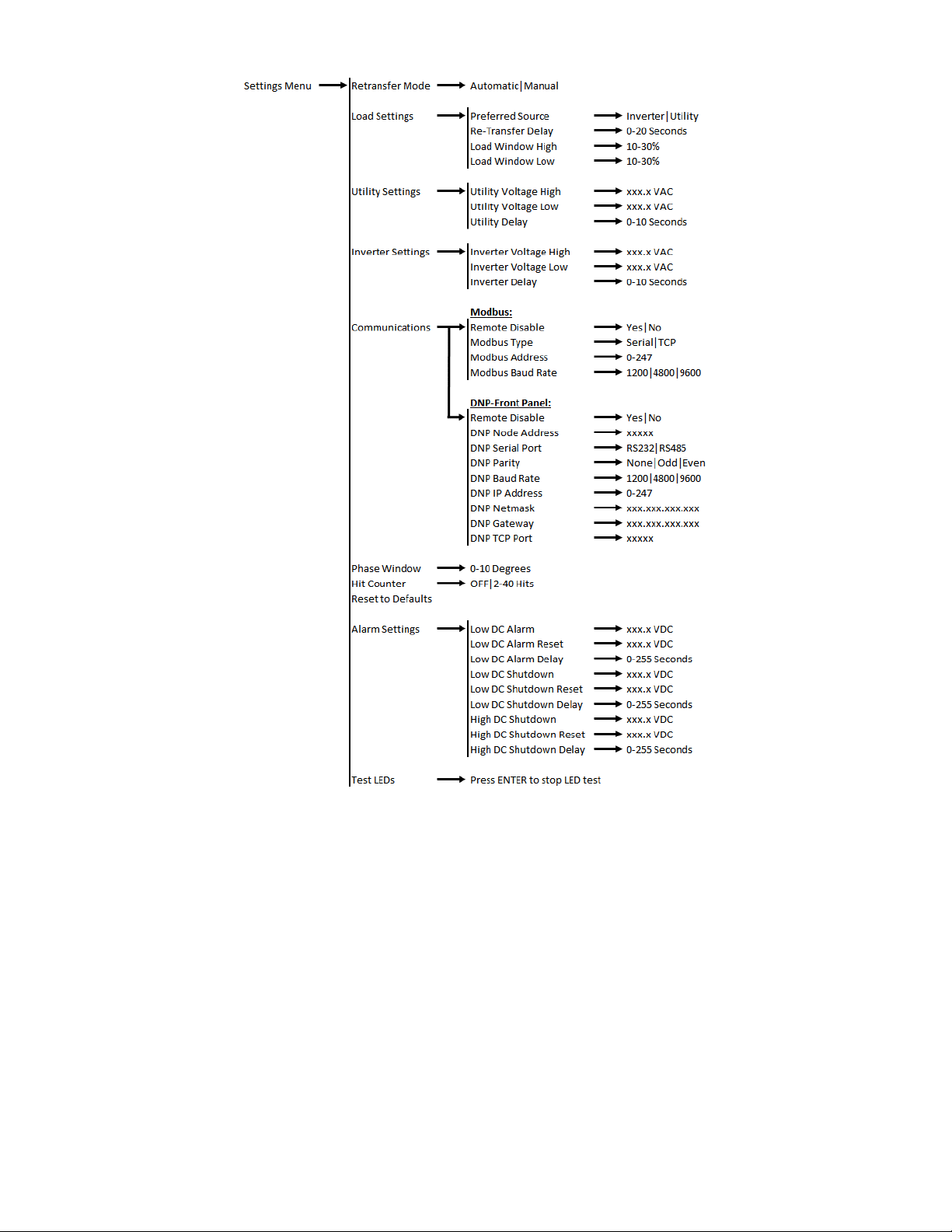
3.1.5 Communications
The communication settings menu changes depending on the type of communication protocol used in the
inverter. For details on connection and operation instructions, refer to the communication instruction
manual included with the inverter.

7
3.1.6 Phase Window
This setting allows the user to adjust the maximum allowable amount of degrees the two sources may have
in difference in order for the sources to be considered out of phase. If the difference is greater, the Phase
Lock LED will turn off. The Phase Window may be adjusted from 1-10 degrees, with 8 being the default
setting.
3.1.7 Reset to Defaults
This setting allows the user to reset all settings to how they were programmed from the factory.
3.1.8 Hit Counter
This setting is used to determine the maximum allowable Load Voltage deviations outside of the predefined
envelope that will trigger a transfer. The Hit Counter may be adjusted from 1 to 40 hits, with 8 being the
default setting.
WARNING: Adjusting the Hit Counter setting will affect the 1-millisecond transfer time. The
higher the Hit Counter value, the slower the transfer time will be. Only adjust if absolutely
necessary.
3.1.9 Alarm Settings
The Alarm Settings menu provides access to adjust basic settings related to the alarms. The user can set
the threshold values that trigger an alarm, that clear an alarm, and the alarm time delays. This applies to
the following alarms: Low DC Voltage, Low DC Voltage Shutdown, and High DC Voltage Shutdown.
When a value is changed and ENTER is pressed, the inverter immediately uses these new values. However,
if the user exits out of the Settings Menu without saving, the threshold values will revert to the previously
set thresholds.
3.1.10 Test LEDs
The Test LEDs menu allows the user to run a basic lamp test on the A31. After selecting this menu, press
the ENTER button to light all of the LEDs on the front panel display. To end the LED test, press the BACK
button.
NOTE: Any additional LEDs on auxiliary boards will not be affected by this LED test.

8
Document Control and Revision History
Part Number: 108859
Instruction Number: P25-LOPT22D-1
Issue ECN: 16282 –12/03
22782 –01/21
16282 –12/03
Table of contents
Popular Measuring Instrument manuals by other brands

ELGO Electronic
ELGO Electronic Z58-SN004 manual

Everfine
Everfine PF9800 SERIES user manual

SGL
SGL TurfPod instruction manual

Lovibond
Lovibond Photometer-System MD100 instruction manual

Endress+Hauser
Endress+Hauser FOUNDATION Proline 500 digital Brief operating instructions

Elma
Elma ELMA-1336 instruction manual