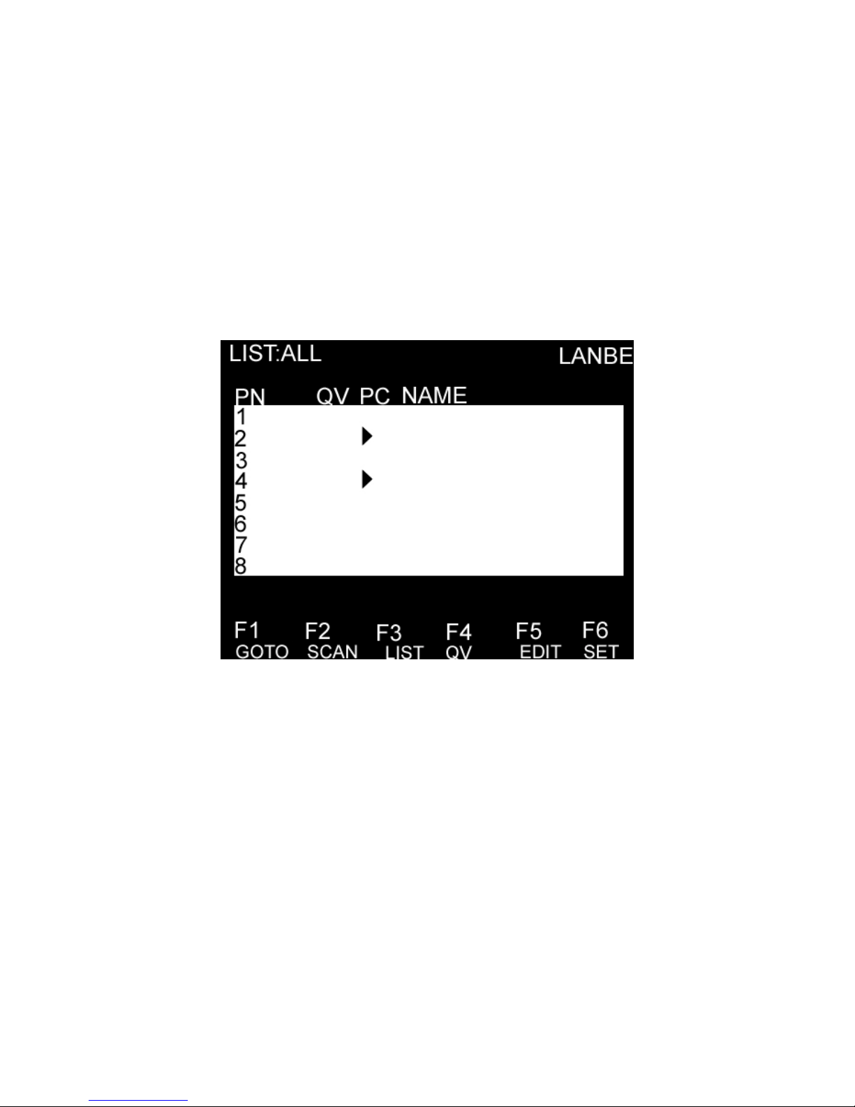
OSD MAIN SCREEN HEADINGS
Heading Explanation
PN This column lists the port numbers for all the CPU ports on the installation. The
simplest method to access a particular computer is to move the highlight bar to it,
then press [Enter].
QV If a port has been selected for Quick View scanning, an arrowhead symbol
displays in this column to indicate so.
PC The computers that are powered on and are on line have an arrowhead symbol in
this column to indicate so.
NAME If a port has been given a name, its name appears in this column.
OSD FUNCTIONS
OSD functions are used to configure and control the OSD. For example, you can: rapidly switch to any port;
scan selected ports only; limit the list you wish to view; designate a port as a Quick View Port; create or edit a
port name; or make OSD setting adjustments.
F1 GOTO:
GOTO allows you to switch directly to a port either by keying in the port’s name or its port number.
To use NAME method, move highlight bar to “NAME”, press [Enter], input name of a port, then press [Enter]
to confirm.
To use PN method, move highlight bar to “PN”, press [Enter], input port number, then press [Enter] to switch.
If the port number is invalid, it will remind the user to input again.
Note: When keying name, if there is a matching name, the matched name will appear on the screen, just press
[Enter] to switch to that port.
To return to main menu, press [Esc].
F2 SCAN
The SCAN function can automatically scan from current selected port, the scan interval can be set by users.
When scanning, a small window on the screen indicates the current port number. Press [Space] to stop scanning,
and the KVM switches to the port last scanned.
F3 LIST
The LIST function lets you broaden or narrow the scope of which ports the OSD displays on the main screen.
Many of the OSD functions only operate on the computers that have been selected for listing on the main
screen with this function. The choices and their meanings are given in the table below:
Choice Meaning
ALL Lists all of the ports on the installation.
QVIEW Lists only the ports that have been selected as Quick View Ports.
POWERED ON Lists only the ports that have their attached computers powered on.
POWERED ON + QVIEW Lists only the ports that have their attached computers powered on and have
been selected as Quick View Ports.