Landis S-500 User manual

Landis S-500
Ortho Sander
Operator Manual
Manufactured by:

1
Introduction
BEFORE USING THE LANDIS S 500 SANDER, READ
OPERATING INSTRUCTIONS MANUAL:
1. KEEP GUARDS IN PLACE and in working order.
2. REMOVE ADJUSTING KEYS AND WRENCHES. Form habit
of checking to see that keys and adjusting wrenches are
removed from tool before turning it on.
3. KEEP WORK AREA CLEAN. Cluttered areas and benches
invite accidents.
4. DON'T USE IN DANGEROUS ENVIRONMENT. Don't use
power tools in damp or wet locations, or expose them to
rain. Keep work area well lighted.
5. KEEP CHILDREN AWAY. All visitors should be kept safe
distance from work area.
6. MAKE WORKSHOP KID PROOF with padlocks, master
switches, or by removing starter keys.
7. DON'T FORCE TOOL. It will do the job better and safer at
the rate for which it was designed.
8. USE RIGHT TOOL. Don't force tool or attachment to do a
job for which it was not designed.
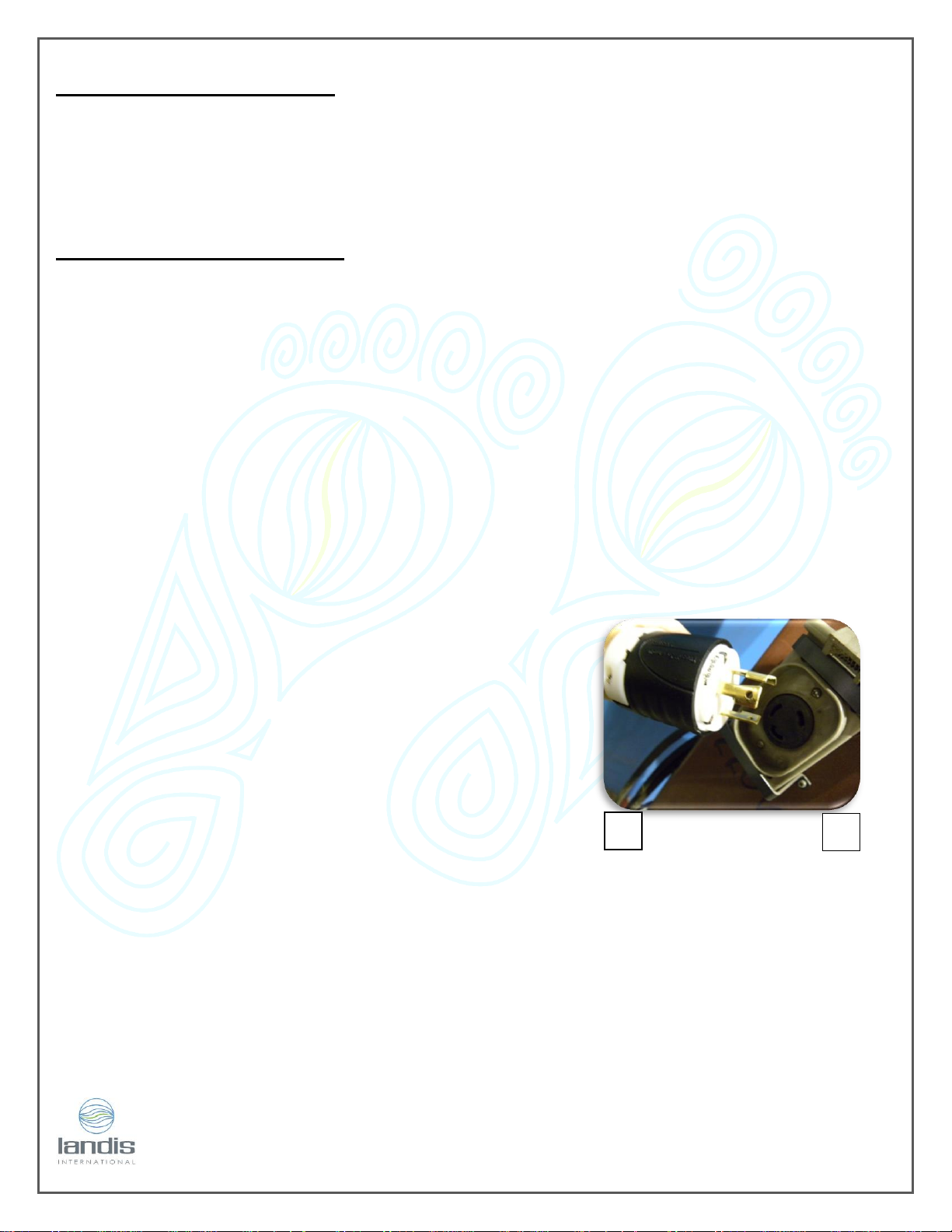
9. DO NOT USE EXTENSION CORD.
10. WEAR PROPER APPAREL. Do not wear loose clothing,
gloves, neckties, rings, bracelets, or other jewellery which
may get caught in moving parts. Nonslip footwear is
recommended. Wear protective hair covering to
contain long hair.
11. ALWAYS USE SAFETY GLASSES. Also use face or dust mask
if cutting operation is dusty. Everyday eyeglasses only
have impact resistant lenses, they are NOT safety
glasses.
12. SECURE WORK. Use clamps or a vise to hold work when
practical. It's safer than using your hand and it frees both
hands to operate tool.
13. DON'T OVERREACH. Keep proper footing and balance at
all times.
14. MAINTAIN TOOLS WITH CARE. Keep tools sharp and clean
for best and safest performance. Follow instructions for
lubricating and changing accessories.
15. DISCONNECT TOOLS before servicing; when changing
accessories, such as blades, bits, cutters, and the like.
16. REDUCE THE RISK OF UNINTENTIONAL STARTING. Make sure
switch is in off position before plugging in.
17. USE RECOMMENDED ACCESSORIES. Consult the owner's
manual for recommended accessories. The use of improper
accessories may cause risk of injury to persons.
18. NEVER STAND ON TOOL. Serious injury could occur if the tool
is tipped or if the cutting tool is unintentionally contacted.
19. CHECK DAMAGED PARTS. Before further use of the tool, a
guard or other part that is damaged should be carefully
checked to determine that it will operate properly and
perform its intended function -- check for alignment of
moving parts, binding of moving parts, breakage of parts,
mounting, and any other conditions that may affect its
operation. A guard or other part that is damaged should
be properly repaired or replaced.
20. DIRECTION OF FEED. Feed work into a blade or cutter
against the direction of rotation of the blade or cutter only.
21. NEVER LEAVE TOOL RUNNING UNATTENDED. TURN POWER
OFF. Don't leave tool until it comes to a complete stop.
The S 500 Sander is a compact, durable machine designed for fast, complete finishing work. It will deliver efficient,
dependable service when used correctly and with care. As with any piece of specialized equipment, for best
performance the manufacturer’s instructions must be followed.

2
RISK OF INJURY
DISCONNECT TOOLS BEFORE SERVICING AND LOCK THE SWITCHES.
EYE PROTECTION SHOULD ALWAYS BE WORN BY THE OPERATOR AND OTHERS IN THE WORK AREA WHEN THE
SANDER IS IN USE.
EYE PROTECTION IS REQUIRED FOR PROTECTION FROM FLYING DEBRIS AND DUST, WHICH COULD CAUSE EYE
INJURY.
AVOID KICK BACK BY SANDING IN ACCORDANCE WITH THE DIRECTIONAL ARROWS.
CLOSE SANDING DOORS BELT BEFORE OPERATING THE MACHINE.
CLOSE THE MAIN ACCESS DOOR AND FAN COVER BEFORE OPERATING THE MACHINE.
INSTALLATION
The Landis S 500 SANDER should be located on a flat, firm surface, in an area free of
obstructions that could interfere with the safe operation of the equipment. The Sander
should be positioned and leveled on the 4 rubber pads to obtain quiet operation with a
minimum of vibration.
ALL ELECTRICAL WORK MUST BE PERFORMED BY A QUALIFIED ELECTRICIAN AND MUST CONFORM TO ALL STATE AND
LOCAL ORDINANCES.
DO NOT, UNDER ANY CIRCUMSTANCE, TAMPER WITH, MODIFY, OR ADAPT THE ELECTRICAL PLUG AND CORD
PROVIDED WITH THIS MACHINE.
ELECTRICAL CONNECTIONS
Electrical connection may be made by either plugging the provided electrical cord into an
appropriately wired electrical socket, or by wiring the machine directly into an electrical
disconnect box.
IF THE ELECTRICAL CORD, PLUG OR WIRING SHOULD BECOME FRAYED OR DAMAGED, REPLACE IT AT ONCE. DO NOT
ATTEMPT TO OPERATE THE MACHINE WITH FAULTY WIRING AS IT COULD RESULT IN SEVERE INJURY OR DEATH.
NOTE: Refer to the machinery identification plate to determine the electrical specifications of
this machine in respect to voltage, phase and amperage requirements.
DO NOT START SANDER BEFORE CHECKING FOR PROPER SANDING BELT TRACKING.

3
ELECTRICAL CONTROL BOX
The electrical control box on back of the machine houses the motor controls on the Sander,
except for the Naumkeag motor that runs on 115 volts (on option). The motor is thermally
protected. In case of overload, the relay will trip and shut the motor off. The overload on
the motor must be reset after a short period of time.
GROUNDING INSTRUCTIONS
In the event of a malfunction or breakdown, grounding provides a path of least resistance
for electric current to reduce the risk of electric shock. This tool is equipped with an electric
cord having an equipment-grounding conductor and a grounding plug. The plug must be
plugged into a matching outlet that is properly installed and grounded in accordance with
all local codes and ordinances.
Do not modify the plug provided -- if it will not fit the outlet, have the proper outlet installed
by a qualified electrician.
Improper connection of the equipment-grounding conductor can result in a risk of electric
shock. The conductor with insulation having an outer surface that is green with or without
yellow stripes is the equipment-grounding conductor. If repair or replacement of the electric
cord or plug is necessary, do not connect the equipment-grounding conductor to alive
terminal.
Check with a qualified electrician or service personnel if
the grounding instructions are not completely
understood, or if in doubt as to whether the tool is
properly grounded.
Use only 3-wire extension cords that have 3-prong
grounding plugs, A, and 3-pole receptacles that accept
the tool's plug, B.
Repair or replace damaged or worn cord immediately.
Make sure the tool is connected to an outlet having the same configuration as the plug. No
adapter is available or should be used with this tool. If the tool must be reconnected for use
on a different type of electric circuit, the reconnection should be made by qualified service
personnel; and after reconnection, the tool should comply with all local codes and
ordinances.
A
B

4
LOCKOUT PROCEDURES
PREPARATION
1. Notify all affected workers that a lockout is required and the reason for the lockout of
the machine.
MACHINE OR EQUIPMENT SHUTDOWN AND ISOLATION
1. If the equipment is operating, shut it down by the normal stopping procedure (turn off
the switch).
2. Disconnect the electrical plug from the electrical source.
APPLICATION OF LOCKOUT / TAGOUT
1. Lock out and tag the switch with an assigned, individual lock. A worker will not be
protected unless he/she uses his/her own padlock.
2. If more than one worker is working on the same piece of equipment at the same time,
each one should lock out the equipment, by placing a personal lock and tag on the
group lockout device when he/she begins work, and should remove those devices
when he/she stops working on the machine or equipment.
3. Locks and tags should clearly show the name of the person who applied the device,
the date, and the reason for the lockout. This identifies who is servicing the machinery
or equipment. In a multiple lockout/tagout situation, it will also identify any worker(s)
who may not have finished working.
4. Locks and tags must be durable enough to withstand the environment in which they are
to be used. Information on the locks and tags should remain legible.
5. Locks must be substantial enough to prevent removal without the use of excessive
force. Tags must be substantial enough to prevent accidental or inadvertent removal.
6. Both locks and tags are to be standardized by colour, shape, or size. Tags should be
easily recognized and provide appropriate information about the lockout.
RELEASE FROM LOCKOUT / TAGOUT
1. Before locks and tags are removed and electricity is restored to the machine, inspect
the work area to ensure that non-essential items have been removed and that machine
components are operationally intact.

5
2. Ensure workers are a safe distance from any potential hazard.
3. The lock and tag should be removed from each energy-isolating device by the worker
who applied the lock and tag.
4. Notify affected workers that locks and tags have been removed.
START-UP
EYE PROTECTION SHOULD ALWAYS BE WORN BY THE OPERATOR AND OTHERS IN THE WORK AREA WHEN SETTING UP
THE MACHINE. EYE PROTECTION IS REQUIRED FOR PROTECTION FROM FLYING DEBRIS AND DUST, WHICH COULD
CAUSE EYE INJURY.
Before shipment, your Landis Sander was checked at the factory for proper adjustment and
operation. However, due to the possibility of jarring or damage during handling and
shipping, it is necessary to check that the machine is in proper working order before use.
BEFORE INITIAL START UP, TURN SANDING BELTS BY HAND TO ENSURE THAT ALL PARTS ARE FREE. DO NOT START
SANDER BEFORE CHECKING FOR PROPER SANDING BELT TRACKING.
BEFORE CONNECTION TO AN ELECTRICAL POWER SUPPLY:
1. Check that the switch is off.
2. Rotate the sanding belts to see that all parts are free and not binding. Continue for one
complete rotation of the sanding belt, checking both belts for tears or other damage.
You can tell that one complete revolution has been made when the joint of the sanding
belt has gone by the front pulley twice.
AS WITH ANY PIECE OF ELECTRICAL EQUIPMENT, THERE IS AN EVER PRESENT HAZARD OF ELECTRICAL SHOCK WHEN
OPERATING OR TOUCHING THE SANDER. ENSURE THE MACHINE IS PROPERLY GROUNDED AT ALL TIMES.
DO NOT FORCE THE EQUIPMENT. IT WILL DO THE JOB BETTER AND SAFER AT THE RATE FOR WHICH IT WAS DESIGNED.

6
BEFORE STARTING THE SANDING BELT MOTOR, CHECK THAT BOTH
SANDING BELTS ARE TRACKING PROPERLY, AS FOLLOWS:
1. "Jog" the sanding belt motor by quickly hitting the "start" and "stop" switch such that the
belts turn slowly, then stop.
2. Continue jogging the motor and check each belt to see that it stays roughly centered
on its forward pulley.
3. Tracking adjustment handles are located to the right of the
sanding belts. Clockwise rotation of the adjustments moves the
belt to the right and counter clockwise rotation moves the belt
to the left. Adjust accordingly as required so that each belt is
tracking properly while running slowly.
4. "Jog" sanding motor switch. Fine adjust the tracking of each belt at full speed.
AS THE INDIVIDUAL SANDING BELTS WEAR FROM USE, IT WILL BECOME NECESSARY TO MAKE MINOR TRACKING
ADJUSTMENTS TO KEEP THE SANDING BELTS CENTERED.
SANDING BELT REPLACEMENT
EYE PROTECTION SHOULD ALWAYS BE WORN BY THE OPERATOR AND OTHERS IN THE WORK AREA WHEN CHANGING
SANDING BELTS. EYE PROTECTION IS REQUIRED FOR PROTECTION FROM FLYING DEBRIS AND DUST, WHICH COULD
CAUSE EYE INJURY.
Sanding belts can be obtained in various grit to suit your needs and are easily changed.
SOME SANDING BELTS ARE CONSTRUCTED TO ROTATE IN ONE DIRECTION ONLY. CHECK ARROW INSIDE SANDING BELT
FOR ROTATION. INCORRECT INSTALLATION CAN CAUSE SUDDEN BELT FAILURE RESULTING IN SERIOUS INJURY TO
OPERATOR AND OTHERS IN THE WORK AREA.
TO REPLACE 1 ½” SANDING BELT:
1. Open right sanding belt door.

7
2. Release pressure on the belt by pushing the grey handle
located in front of the machine.
3. Reach in access door and remove the far end of the belt off
the idler first.
4. Remove built-up dust on the rubber sanding wheel and on the
idler drum.
5. To install the new sanding belt, reverse the procedure described above, then readjust
the tracking as described earlier in section “start-up”.
TO REPLACE 4” WIDE BELT ON LEFT SIDE:
1. Open left sanding belt door.
2. Release pressure on the belt by pulling the grey handle located
in front of the machine.
3. Reach in access door and remove the far end of the belt off
the idler first.
4. Remove built-up dust on the rubber sanding wheel and on the idler drum.
5. To install the new sanding belt, reverse the procedure described above, then readjust
the tracking as described earlier in section “start-up”.
TO REPLACE 4” WIDE BELT ON RIGHT SIDE:
1. Open sanding belt door.
2. Release pressure on the belt by pushing the grey handle.

8
3. Reach in access door and remove the far end of the belt off the idler first.
4. Remove built-up dust on the rubber sanding wheel and on the idler drum.
5. To install the new sanding belt, reverse the procedure described above, then readjust
the tracking as described earlier in section “start-up”.
DO NOT START SANDER BEFORE CHECKING FOR PROPER SANDING BELT TRACKING.
DO NOT OPERATE MACHINE WITH ACCESS DOOR OPEN.
NEVER LEAVE MACHINE RUNNING WHILE UNATTENDED. TURN IT OFF.
AS INDIVIDUAL SANDING BELTS WEAR FROM USE, IT WILL BECOME NECESSARY TO MAKE MINOR TRACKING
ADJUSTMENTS TO KEEP SANDING BELTS CENTERED.
LONGER LIFE OF YOUR SANDING BELTS
After you have used a sanding belt for a while, you will find it
does not cut as fast as new. When belts cut too slow reverse
them, only if the sanding belt can run either way. Here is how:
Turn belt over and remount.
N.B. After reversing a belt, check tracking.

9
ACCESSORIES
EYE PROTECTION SHOULD ALWAYS BE WORN BY THE OPERATOR AND OTHERS IN THE WORK AREA WHEN USING THE
ACCESSORIES SUPPLIED WITH THE LANDIS SANDER. EYE PROTECTION IS REQUIRED FOR PROTECTION FROM FLYING
DEBRIS AND DUST, WHICH COULD CAUSE EYE INJURY.
ACCESSORIES ON QUICK CHANGE BAYONET FITTING:
Both ends of the sanding shaft are machined to accommodate bayonet fitting (quick
change). Extra tools and sanding wheels are available on request. See the list at the end of
this book.
When removing the quick change fittings, use the special spanner
wrench supplied with the machine. To remove, engage the
spanner in the hole near the end of the bayonet fitting and apply a
sharp rap downward. Before putting on a fitting be sure the
machine surfaces are clean. Hand tightening is sufficient to hold
the fitting in proper position.
FAILURE TO PROPERLY MOUNT THE ADAPTOR WILL RESULT IN FLYING APART AND POSSIBLE INJURY TO THE OPERATOR
AND OTHERS IN THE WORK AREA.
THESE QUICK CHANGE ACCESSORIES SHOULD BE PROPERLY ENGAGED ON THE SHAFT TO ENSURE SAFE OPERATION.
MAKE SURE PIN ON SHAFT ENGAGES THE ADAPTOR CORRECTLY.
SPANNER WRENCH
When removing the quick change fittings, use the black spanner wrench supplied with the
machine. To remove, engage the spanner in the hole near the end of the bayonet fitting
and apply a sharp rap downward. Before putting on a fitting be sure the opening ends are
cleaned. Hand tightening is sufficient to hold the fitting in proper position.
N.B. When properly mounted, the bayonet fitting will tighten itself by rotating it in the socket
in the opposite direction of the sanding belt rotation.
HEEL BREASTER ON BAYONET:
A Heel breaster mounted on a quick change adaptor is provided with
your Sander and can be used on the left side of the main shaft.

10
Verify that the sandpaper is well placed on the cone so that the 2 ends of it are in the
groove of the cone.
MAINTENANCE
A properly maintained machine will give you years of satisfactory service, whereas an
abused machine will not. We strongly recommend that you observe the following
procedures for your own benefit and safety.
EYE PROTECTION SHOULD ALWAYS BE WORN BY THE OPERATOR AND OTHERS IN THE WORK AREA WHEN SERVICING THE
MACHINE. EYE PROTECTION IS REQUIRED FOR PROTECTION FROM FLYING DEBRIS AND DUST, WHICH COULD CAUSE
EYE INJURY.
DAILY AND WEEKLY MAINTENANCE
1. Clean your Landis Sander daily.
2. Shake dust bags and empty dust drawer daily.
After cleaning the machine, turn dust extraction motor off. While the
motor is coasting to a stop, shake bag vigorously.
Open the front door. Unscrew the black handles to
open dust drawer.
Remove the large dust tray, remove dust.
Check seal around drawer and replace if damaged or if it is not
sealed properly.
Check the ring at the bottom of the dust bag. Make sure that the
ring is well snapped into the round hole.
When the dust drawer is full, dust may spill when the drawer is removed. Vacuum
out the bottom of the machine before replacing the drawer for the last time.

11
The cleaner you keep the dust bags, the less likely you are to burn a hole in
them. Failure to shake the dust bags and empty the dust drawer daily will only
increase this likelihood, but also cause a significant loss of dust extraction.
3. 4" Felt or rubber sanding wheel:
Clean the felt or rubber surface to avoid accumulation of dust. If
there is too much accumulation, the sanding belt won’t stay on the
felt or rubber wheel and you will have problems with tracking.
4. Idler wheel 4":
Clean the flat surface to avoid accumulation of dust.
DUST FROM SANDER IS COMBUSTIBLE. DO NOT SMOKE WHILE CLEANING THE MACHINE AND DUST COLLECTOR.
DAMAGED DUST BAG OR DUST DRAWER SEALS WILL ALLOW THE ESCAPE OF COMBUSTIBLE MATERIALS CAUSING A FIRE
HAZARD AROUND THE MACHINE.
CHECK DAMAGED PARTS. BEFORE FURTHER USE OF A TOOL, GUARD OR OTHER PART THAT IS DAMAGED, CHECK
CAREFULLY TO DETERMINE THAT IT WILL OPERATE PROPERLY AND PERFORM ITS INTENDED FUNCTION. CHECK FOR
MOUNTING OR ANY OTHER CONDITION THAT MAY AFFECT ITS OPERATION. A TOOL, GUARD OR OTHER PART THAT IS
HARMFULLY DAMAGED SHOULD BE PROPERLY REPAIRED OR REPLACED.
IF THE ELECTRICAL CORD, PLUG OR WIRING SHOULD BECOME FRAYED OR DAMAGED, REPLACE IT AT ONCE.
REPLACE ALL DOORS AND GUARDS BEFORE OPERATING THE MACHINE.
DO NOT OPERATE MACHINE WITH SANDER HOUSING DOORS OPEN.
AFTER MAKING ADJUSTMENTS, REMOVE ALL WRENCHES AND OTHER TOOLS BEFORE OPERATING THE SANDER.
USE EXTRA CAUTION WHEN STARTING THE SANDER FOR THE FIRST TIME AFTER INSTALLING A NEW TOOL OR PART.
MONTHLY MAINTENANCE
1. Check the felt or rubber sanding pulleys surface for any accumulation of
dust. Clean if necessary. Replace the wheel if worn.
2. V-Belts –Check tension and adjust if necessary.

12
YEARLY MAINTENANCE
BEFORE REMOVING DUST BAGS, DISCONNECT ELECTRICAL POWER SUPPLY.
Once a year you should remove the dust bags for a thorough cleaning.
The dust bags are removed by:
1. From the back of the machine, unsnap the top of each bag.
2. Remove the dust bags by pushing on the ring at the bottom of each
bag.
3. You can use a vacuum cleaner to clean both inside and outside of the dust bag.
4. Replace the dust bags.
LUBRICATION
Your Landis Sander is equipped with sealed bearings throughout, which should be replaced
if they ever wear out.
Other parts should not require any lubrication, only cleaning the parts is required.
Lubrication will only attract dust and would be more harmful than helpful.
V-BELT ADJUSTMENT AND REMOVAL
The 2 V-Belts on the Landis Sander should be checked monthly for proper tension and
general condition. Loose V-Belt will decrease the power available to the various tools and
lower the efficiency of your Sander.
If you discover a worn or frayed belt, replace it now so it won’t break at an
inconvenient time.

13
DISCONNECT ELECTRICAL POWER SUPPLY BEFORE WORKING ON THE MACHINE.
TO CHECK V-BELT TENSION
1. Disconnect the electrical power supply.
2. Check the tension of the V-belt running to the motor; it should depress
approximately ½” when pressed in the middle with moderate force.
3. Rotate the V-belt by hand, visually inspecting the belt for damage.
4. If tensions or conditions are bad, adjust tension or replace V-belt.
To adjust the tension, unscrew the nuts on the 2 threaded rods. Move
the motor plate up or down accordingly to your needs.
DO NOT OVER TIGHTEN V-BELT, AS TO DO SO WILL CAUSE RAPID BELT WEAR AND PREMATURE BEARING FAILURE.
AFTER MAKING ADJUSTMENTS, REMOVE ALL WRENCHES AND OTHER TOOLS BEFORE OPERATING THE SANDER.

14
MOTORS REPLACEMENT
MOTOR REPLACEMENT REQUIRES WORKING WITH ELECTRICAL WIRING AND CAN BE HAZARDOUS. IF YOU ARE NOT
FAMILIAR WITH ELECTRICAL PROCEDURES, PLEASE CALL A QUALIFIED ELECTRICIAN.
SANDING MOTOR
To remove the motor, these procedures should be followed:
1. Disconnect the electrical power supply.
2. From the rear of the machine, remove the four (4) screws, nuts, and
washers holding the motor. Remove V-belt.
3. Remove motor electrical box plate and observe the electrical wires
connected.
4. Mark the electrical wires to the motor such that you will be ABSOLUTELY
CERTAIN where to reconnect them to the new motor.
5. Disconnect the electrical wires and the connector on the motor box.
6. Disconnect the electrical wiring by removing the electrical plate on the
end of the motor. Mark the electrical plate on the end of the motor.
Mark the electrical wires to the motor such that you will be ABSOLUTELY
CERTAIN where to reconnect them on the new motor.
7. Reassemble with new motor in reverse order to the above procedures.
BE ABSOLUTELY CERTAIN TO RECONNECT THE ELECTRICAL WIRE TO THE PROPER TERMINALS.
FAILURE TO DO SO CAN RESULT IN IMPROPER MOTOR ROTATION, A RUINED MOTOR, FIRE, OR INJURY TO YOURSELF.

15
NAUMKEAG MOTOR (OPTION)
To remove the Naumkeag motor, these procedures should be followed:
1. Disconnect the electrical power supply.
2. Remove the complete unit by taking off the Naumkeag knob.
3. Remove four (4) screws, nuts and washers that hold motor to swivel plate.
Remove motor.
4. Loosen set screw on Naumkeag shaft and pull out the adapter from the
shaft motor.
5. Reassemble with new motor in reverse order to above procedures.

16
OTHER PARTS REPLACEMENT AND ADJUSTMENT
SANDING SHAFT AND BEARING REPLACEMENT
Before removing sanding shaft and bearings, disconnect the
power supply.
1. Take, the two bayonet off the machine.
2. Remove the front cover that is hidings the bearings.
3. Remove the 2 sanding belts from the machine.
4. Unscrew the screws on the two felt or rubber wheels to slide those
out of the main shaft.
5. Take off the V-Belt on the pulley. Leave it on the side between the
bearing and the pulley. It will come out when you will pull the shaft.
6. Unscrew the two Allen set screws on the pulley.
7. Unscrew the 2 Allen set screws on each bearing and slide the shaft
out on the left side. If there are marks or burrs on the shaft, sand
those with fine sandpaper.
8. Unscrew the 2 hexagonal bolts on each bearing to change them.

17
Make sure to align the 2 new bearings to get the horizontability off
the main shaft.
9. Reverse procedure to assemble and don’t forget to put back the V-
Belt on the shaft before sliding it in the first bearing.
FRONT DOOR HANDLE ADJUSTMENT
If the door is not attached firmly to the machine you have to tight the
hexagonal bolt on the handle to adjust.
If you can not close the handle, you have to unscrew the hexagonal
bolt on the handle.
HOW TO CHANGE THE IDLER WHEEL ASSEMBLY
1. Disconnect the electrical power supply.
2. Remove the sanding belt from the machine. First take out the
tension on the idler wheel with the tension arm.
3. Remove the orange end cap.
4. Unscrew the hexagonal nut to take out the spring. Be careful: hold
the spring with a pincer.
5. Unscrew the hexagonal bolt to dismantle the idler arm from the
releasing system.

18
6. To take out the complete idler wheel assembly, unscrew the ¾"
hexagonal bolt.
NOTE: You need somebody to retain the idler when the mechanic is doing
this operation.
7. Install the new idler wheel assembly. Make sure that the tracking T
arm is parallel with the sanding belt.

19
TROUBLE SHOOTING
LOST OF SUCTION IN DUST COLLECTION
1. Dust drawer may be full. Empty it.
2. Blower fan may be clogged. Clean it.
3. Sander too close to the back wall. Your Sander should be 6”
distance from the wall.
BELT CREEPS
1. Belt worn out or frayed one side. Install new belt.
MOTOR STOPS WITH SWITCH ON
CAUTION: TURN SWITCH OFF IMMEDIATELY
1. Too much equipment operated on same circuit on which Landis S-500 Sander is
connected. Check circuit breaker or fuse box.
2. An overload may have caused the thermal overload protector in motor to shut off
current. Be sure sander is off, then find and eliminate cause for overload. Motors are
equipped with manual Re-Set thermal overload protector wait at least 15 minutes, then
firmly press Re-Set button on motor with eraser end of pencil or a small blunt dowel.
After approximately 30 minutes you should be able to hear or feel overload protector
click in when pushed to reset. After Re-Set clicks in, turn switch on and motor should run
normally.
SANDING BELT 4” DOESN’T STAY ON THE FELT OR RUBBER WHEEL
1. Pull or push the release tension arm to put at the right
place.
2. Secondly verify if there is dirt or dust clogged on the front wheel.
If so, clean it with a scraper or a sandpaper.
3. Check on the back of the machine is the spring is giving enough
tension to the idler wheel.
Table of contents
Other Landis Sander manuals