INSTALL GUIDE
•The product should not be exposed to any dripping or splashing liquid.
oduct.
•Keep the remote control battery away from children. Dispose of used battery promptly,
replace only with a battery of the correct type.
•Protect the power cord from damage. Do not pull push the power cord excessively, and take
care not to let the power cord become pinched, particularly at or near the plug.
•Keep the product away from heat sources such as heat registers, stoves or other appliances
that produce heat.
•Avoid direct sunshine and covering vents. Do not operate in a sealed box and be sure to
have enough room for heat exchange.
•Avoid opening the cover. Do not open the cover, or touch the inner parts, refer servicing to
our customer service.
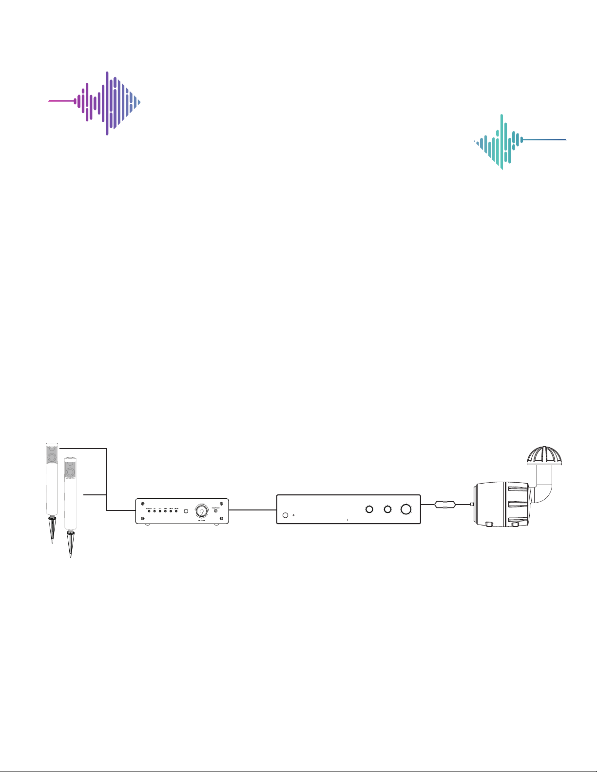
LV-SA45 TUNER LV-SA250 SUBWOOFER AMPLIFIER
TUNER FEATURES
1. Power Indicator
2. Bluetooth®Indicator
3. OPT Indicator
4. USB Indicator
5. Wi-Fi®Indicator
6. Line In Indicator
7. Volume Knob/Input Selector
8. Head Phone Jack
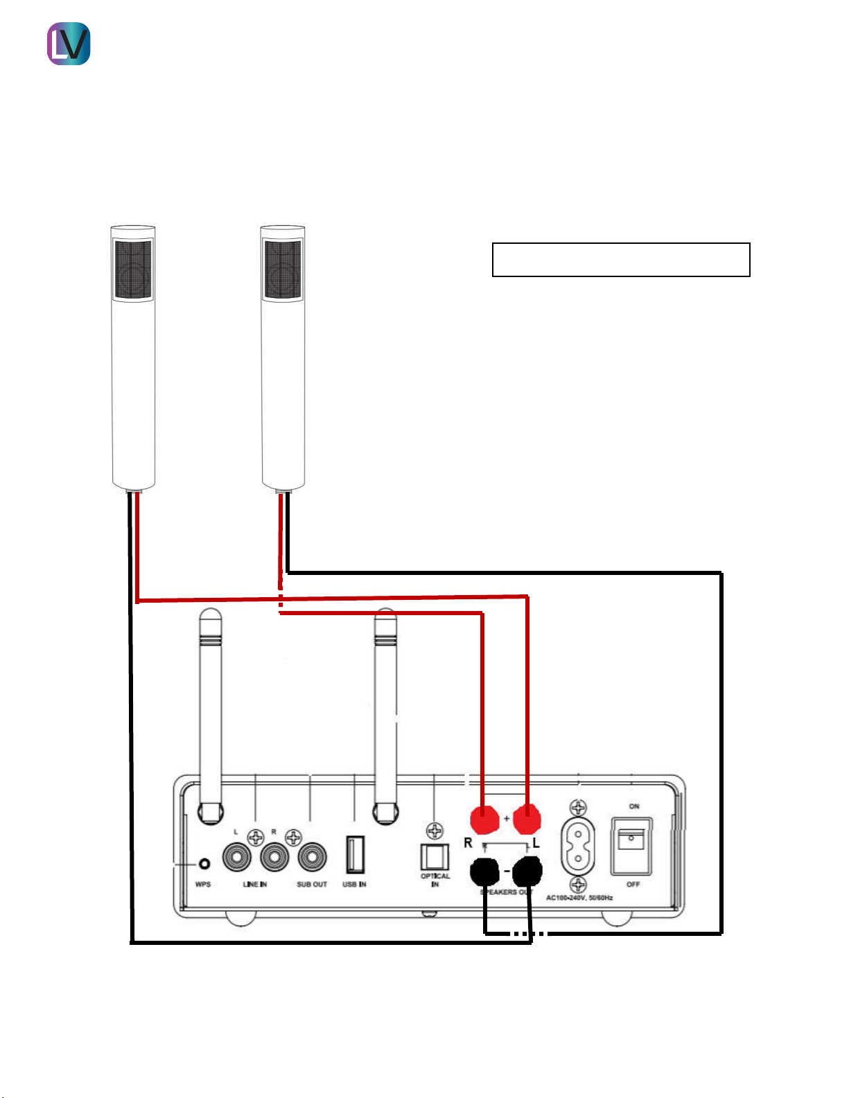
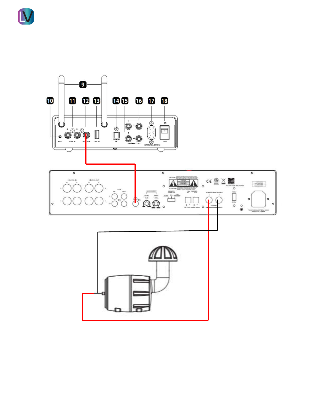
9. Antenna
10. WPS
12. SUB Out
11. Line In
13. USB In
14. Optical Input
15. Speaker Output -L/R
16. Speaker Output + L/R
17. Power Input
71 2 3 4 5 6 8
9
15 16
1110 12
13
14 17 18
POWER
PHASE
0¡
90¡
180¡
0
5
10
40¡
120¡
zH ¡081
FREQ GAIN
FRONT PANEL:
1. Power Switch / Indicator LED
Front panel pushbutton power switch turns the amplifier on and off. When the indi-
cator LED is lit dimly, the amplifier is in standby mode. When the LED is lit brightly,
the amplifier is fully active.
2. Phase
Adjustable phase compensation from 0 to 180 degrees. Corrects phase anom-
alies that result from differing listening distances between the subwoofer and
main speakers, which can cause poor acoustic summation around the crossover
point. In most situations the control knob should be left at 0 degrees, but for the
advanced user it can be set either by ear or with the aid of measurement instru-
ments.
3. Frequency
Adjusts the low-pass crossover frequency from 40 Hz to 180 Hz. When using the
Left/Right inputs, this adjustment will allow you to properly integrate the sub-
woofer with the satellite or main speakers. It is recommended to experiment with
different settings until the smoothest transition between subwoofer and speakers
is achieved.
4. Gain
Sets the overall level of the amplifier, used to match the output of the subwoofer to
the rest of the speakers in the system. If the source output has a variable control,
we recommend that the user spend a moment or two determining the best balance
between the two controls. When a balance is found between low noise, linear level
control, and sufficient level to drive the amp to the required output, the gain knob
can be considered to be the “volume control” for the subwoofer system.
REAR PANEL:
5. High-Level Inputs
Speaker level inputs terminated with binding post jacks that are compatible with
banana-type plugs, bare wires, or spade terminals. These inputs facilitate connec-
tion of a full-range amplifier’s speaker level output to the input of the subwoofer
amp, using standard speaker wire. A mono signal is derived from the stereo
source, which then feeds the subwoofer amplifier crossover input.
6. Line Inputs
RCA-style jacks receive the audio signal from standard line-level audio sources.
When used in a two-channel stereo system, both the left and right audio inputs
should be connected and are internally summed to a mono output. The adjustable
crossover is in effect when using the left or right inputs. When using an amplifier
with an audio source that is mono and pre-filtered, the LFE input should be used;
this bypasses the onboard low-pass crossover for more accurate reproduction of
the incoming signal.
NOTE: Bass Boost is active on LFE and L/R inputs.
7. Bass Boost
Allows the user to add boost to the low end response by selecting a bass boost
frequency from 25 Hz to 50 Hz and a boost level from 0 to 12 dB. Simply remove
clear acrylic cover to access controls.
8. Remote Turn On
Selects the turn-on stimuli that will put the amplifier in “Ready” mode. “12V trigger”
setting relies on voltage going into the 12V trigger input to activate the amplifier.
“Auto” setting senses a signal on the RCA line-level inputs and automatically puts
the amp in ready mode. “On” setting puts the amp constantly in “Ready” mode so
that it can be controlled by the master power switch on the front panel. In “Auto”
mode, the amplifier will take approximately 15 minutes to turn off from “Ready” to
“Standby” mode.
9. 12V Trigger Input
The 12V trigger input is a handy feature when connecting the amplifier to an auto-
mated audio system. The Phoenix connectors will accept up to a 12V DC output
from another device, or from a separate power supply. When the trigger input is
energized, the amp turns from “Standby” to “On” mode. When using the SAM300
with a home theater receiver without a trigger output, the voltage can come from
a 12V “wall wart” plugged into the receiver’s switched outlet and the amplifier’s
trigger input.
10. Speaker Outputs
Speaker level output connections carry the amplified signal to the subwoofer
drivers. The binding posts will accept bare wire, banana plugs, or spade plugs.
NOTE: The output load must have a minimum of 4 ohms impedance!
11. Voltage Selector Switch
This switch allows the user to select 120V or 240V operation. The unit is set at the
factory for 120V operation and contains a 5A, 250V fuse. When operating at 240V
be sure to change the fuse to a 2.5A, 250V fuse.
12. AC Power
The SAM300 is shipped standard for U.S. operation; simply connect the included
IEC power cord to your wall outlet. For overseas operation, a separate power cord
may be required and is not included. In stand-by mode it draws less than 1 watt.
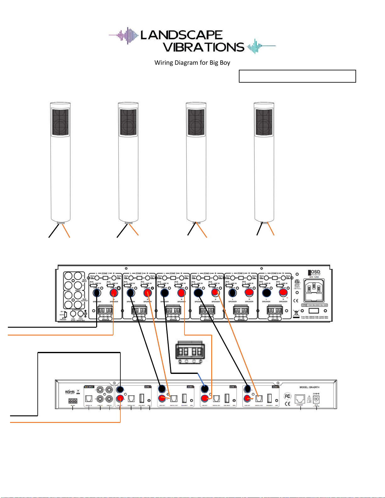
www.landscapevibrations.comwww.landscapevibrations.com