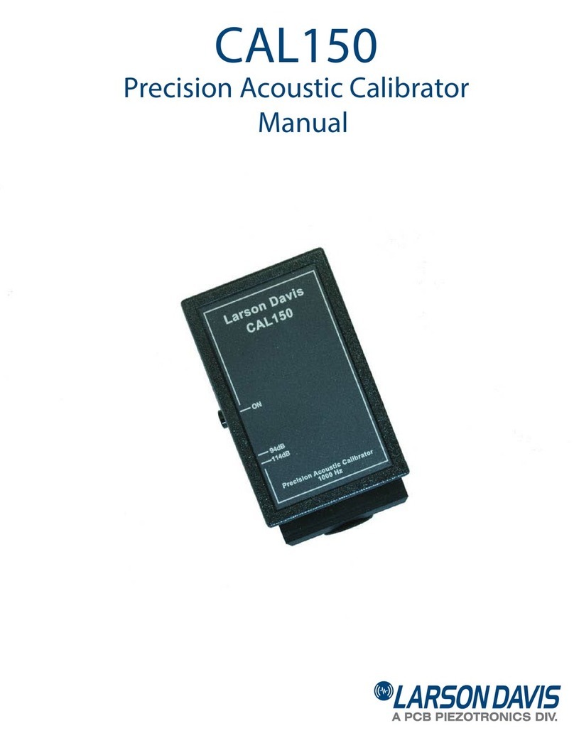
Larson Davis CAL200 User manual

CAL200
Precision Acoustic Calibrator
Manual


I200.1 Rev H
APPENDIX
Larson Davis
CAL200
Manual

Copyright
Copyright 2006-2015 by PCB Piezotronics, Inc. This manual is copyrighted, with all rights reserved.
The manual may not be copied in whole or in part for any use without prior written consent of PCB
Piezotronics, Inc.
Trademarks
PCB®is a registered trademark of PCB, Inc.
Disclaimer
The following paragraph does not apply in any state or country where such statements are not
agreeable with local law:
Although PCB Piezotronics, Inc. has reviewed this documentation, PCB Piezotronics Inc. makes no
warranty or representation, either expressed or implied, with respect to this instrument and
documentation, its quality, performance, merchantability, or fitness for a particular purpose. This
documentation is subject to change without notice, and should not be construed as a commitment or
representation by PCB Piezotronics, Inc.
This publication may contain inaccuracies or typographical errors. PCB Piezotronics, Inc. will
periodically update the material for inclusion in new editions. Changes and improvements to the
information described in this manual may be made at any time.
Recycling
PCB Piezotronics, Inc. is an environmentally friendly organization and encourages our customers to
be environmentally conscious. When this product reaches its end of life, please recycle the product
through a local recycling center or return the product to:
PCB Piezotronics, Inc.
Attn: Recycling Coordinator
1681 West 820 North
Provo, Utah, USA 84601-1341
where it will be accepted for disposal
Product Warranty
For warranty information, refer to our Terms and Conditions of Sale on our website at
www.larsondavis.com/TermsConditions.aspx.

CAL200 Manual Introduction 1-1
CHAPTER
1Introduction
This chapter describes the features of the Larson Davis
CAL200 Sound Level Calibrator.
Features
The Larson Davis CAL200 sound level calibrator is a
battery operated, precision instrument used for calibrating
sound level meters and other sound measurement
equipment. It provides an output level of either 94.0 or 114.0
dB (switch-selectable) at a frequency of 1 kHz. It has been
designed for both field and laboratory use and the accuracy
has been calibrated to a reference traceable to the National
Institute of Standards and Technology.
The Larson Davis CAL200 Sound Level Calibrator has the
following features:
• Precision sound level calibrator
• Dual output levels: 94.0 dB and 114.0 dB (user
selectable)
• Output frequency 1 kHz
• Internal batteries for portable operation
• Opening for use with 1/2” microphones
• Adaptor ADP031 available for use with 3/8”
microphones
• Adaptor ADP024 available for use with 1/4”
microphones
• Adaptor ADP075 available for use with 1/8”
microphones

1-2 Features CAL200 Technical Reference Manual

CAL200 Manual Using the CAL200 Calibrator 2-1
CHAPTER
2Using the CAL200 Calibrator
This chapter describes how to operate the CAL200
calibrator.
Installing the Battery
The CAL200 uses a nine-volt battery and it is recommended
that you use an alkaline battery to extend the running time of
your calibrator. The CAL200 will run for approximately 100
hours on one nine-volt battery when using the 114 dB output
level. This will give you nearly 4200 calibrations.
Follow the steps below to install the battery:
Step 1 Slide the battery door on the lower section of the
back panel up to remove it.
Step 2 Gently pull the battery connector clip sufficiently
outside the interior to permit it to be snapped onto the
battery terminals.
Step 3 Tuck the battery, with the battery connector clip
attached, into the battery compartment
Step 4 Slide the battery door back into place, pressing
until the tab snaps the door securely shut.
Microphone Calibration
The CAL200 provides a nominal tone of 1 kHz, which
requires no weighting corrections when used with sound
level meters utilizing A, B, C or Z (Flat) frequency
weighting.

2-2 Microphone Calibration CAL200 Manual
Select the Output Level
The output level is user-selected to be 94.0 or 114.0 dB
using the slide selector on the side of the CAL200. Slide the
switch to lower position for 114.0 dB or to the upper
position for 94.0 dB, as indicated by the label on the lower
left of the front panel.
CAL200 Used to Calibrate an Instrument with ½" Free-Field Microphone
The CAL200 provides a nominal pressure level of 94 dB or
114 dB. The exact levels are printed on the Larson Davis
calibration sheet that came with the calibrator. When using a
free-field microphone, the pressure level at the microphone
diaphragm will be slightly different. Thus, a free field
correction of -0.12 dB should be applied to either of these
levels. Pressure and random incidence microphone do not
require a correction of this type. If the calibrator and
instrument are near room temperature (23° C) and near sea
level (101.3 kPa) then no other corrections need to be made.
If the calibration sheet for the CAL200 indicates 113.98 dB
for its level when set to 114 dB then set the Cal Level in the
instrument to 113.86 dB and 1 kHz.
When the microphone and instrument are at a temperature
other than near room temperature or static pressures not near
sea level, then corrections will need to be added for the
ambient temperature and the prevailing static pressure.
Check the calibration data shipped from Larson Davis with
the CAL200 to get these corrections. The corrections can be
added to the level obtained in the previous paragraph to get
the actual level of the CAL200. The microphone's sensitivity
varies with static pressure. If the instrument is calibrated in
one environment and moved to another, then the sensitivity
will change (after stabilization) depending on the change of
temperature and pressure. The coefficient of static pressure
is typically -0.013 dB/kPa for PCB®½” free-field
microphones. If the system is calibrated at 85 kPa, for
instance, then it will be 0.21dB less sensitive at sea level.
The sensitivity of the microphone varies slightly with
temperature also. The coefficient of temperature is typically
-0.009 dB/°C for PCB ½” free-field microphones. If the
system is calibrated at 18 °C then it will be 0.05 dB less
sensitive at 23 °C.

CAL200 Technical Reference Manual MicrophoneCalibration 2-3
Perform the Calibration
To calibrate the microphone, follow the steps below:
WARNING! Do not remove the
microphone gridcap while
calibrating as this may lead to
microphone damage.
Step 1 Place the instrument so that you can perform the
calibration vertically, as shown in Figure 2-1.
Step 2 Insert the proper microphone adapter fully into the
calibrator. Make sure it fits snugly.
Step 3 Insert the microphone fully into the adapter. Make
sure it fits snugly.
The preferred method for calibrating
with the CAL200 is to mount the
preamplifier in a fixed, vertical
position.
FIGURE 2-1 Vertical Positioning
Step 4 With the microphone connected to the instrument
being calibrated, press the CAL200’s ON button. With a
fresh battery, the calibrator will issue a tone for more than 60
seconds before automatically shutting off (see note below).
Top: calibrator stands
vertically above mounted
preamplifier.
Bottom: mounted
preamplifier,
fixed vertically

2-4 Microphone Calibration CAL200 Manual
Step 5 Make a reading. If the reading is not within
tolerance, refer to the instrument’s manual for instructions
on how to adjust the instrument.
Step 6 Check the ambient noise level to insure that the
calibration was not influenced by noise from external
sources. The CAL200 needs to be on the microphone but
with the CAL200 signal off. External noise levels lower than
89 dB SPL for the 114 dB level calibration, and 69 dB SPL
for the 94 dB calibration level will influence the calibration
by less than 0.015 dB.
Each time the ON button is pressed,
the CAL200 calibrator will run
approximately 60 seconds on a fresh
battery. In order for the calibrator to
turn off, do not press the ON button
again. Wait until the calibrator times
out. It is not an ON/OFF button.
As the battery becomes weaker, the calibration tone will not
deteriorate, but the operating time will decrease until the
time is too short to accomplish an adequate calibration.
When making a sequence of measurements, a calibration
check and an adjustment (if necessary) of the instrument
should be made at the beginning. At the end of the
measurement sequence, the calibration should be checked
again. The inaccuracy of the measurements will be at least
as large as the difference between the level measured for the
initial calibration (or calibration check) and the level
measured for the final calibration check.
Calibration History
Larson Davis strongly recommends that a history of each
calibration adjustment be kept for each piece of equipment.
Normally, most modern equipment requires little or no
adjustment once the initial calibration is performed.
Systematic drifts are possible, and these should be recorded
for corrective action.
Most Larson Davis sound level meters keep a history of each
calibration change that can be printed before an overall reset.
Please refer to the individual instrument manuals for details.
Environmental Precautions
While the CAL200 will perform normally under a wide
variety of gradually changing environmental conditions,

CAL200 Technical Reference Manual MicrophoneCalibration 2-5
some precautions should be taken when sudden changes
occur:
• The temperature of the CAL200 should be stable. If the
temperature changes suddenly, provide a stabilization
time of at least 15 minutes. This will ensure that the
temperature compensation sensors are at the same
temperature as the rest of the unit.
• While humidity will not affect the CAL200, avoid
condensing moisture. Also, avoid environments over
90% relative humidity because condensation can easily
take place.
• The CAL200 is insensitive to magnetic fields. However,
the instrument being tested may not be. Therefore,
calibration should not be done near motors, dynamos,
high voltage wires, or other sources of electromagnetic
fields.
Calibrator Calibration
The American National Standards Institute states, “An
acoustical calibrator should be recalibrated at least annually
by the instrument manufacturer or an acoustical test
laboratory qualified to perform calibration.” (American
National Standards Institute. Specifications for Acoustical
Calibrators. ANSI S1.40, 2006, par. 5.2)
Larson Davis believes the frequency of recalibration
depends on the number of calibrators being used and the
number of instruments being calibrated. With this in mind,
the following guidelines are presented for your
consideration:
If a systematic drift of several dB
occurs, there is no reliable way to
verify which instrument is at fault,
even though it is more likely to be the
measurement instrument.
• For one calibrator and one measurement instrument, the
CAL200 should be certified at least yearly.
• For one calibrator and several measurement instruments,
one calibration a year is recommended. but if no
systematic drift occurs, every two years might be
satisfactory.
• For several calibrators and several instruments, one
calibration a year is recommended.

2-6 Microphone Calibration CAL200 Manual
If the CAL200 is being used to calibrate several instruments,
then the history of calibration adjustments can usually
pinpoint which instrument is drifting. If all the measurement
instruments are drifting in the same direction by an amount
you consider significant, the CAL200 should be recertified.
If several instruments and several calibrators are in use, then
the history of calibration adjustments would precisely
pinpoint any problem pieces of equipment. Furthermore, it is
probably satisfactory to recalibrate only one of the
calibrators each year.

CAL200 Manual Specifications A-1
APPENDIX
ASpecifications
The specifications contained in this chapter are subject to
change without notice. Please refer to calibration and test
results for data on a specific unit.
Standards Met
• ANSI S1.40-2006, Specifications and Verification Proce-
dures for Sound Calibrators, Class1
• IEC 60942-2003, Class 1, Sound Calibrators
• IEC 61010-1:2001, Safety requirements for electrical
equipment for measurement, control, and laboratory use
- Part 1 General Requirements
• IEC 61326-1:2005, Electrical equipment for measure-
ment, control, and laboratory use - EMC requirements
Technical Specifications
Measurement uncertainty and coverage factor information
is shown on test reports that ship with the calibrator.
Calibration sound pressure level 94.0 dB and 114.0 dB ± 0.2 dB
re: 20Pa @ 101.3 kPa, 23 ºC and 50% RH
(114.0 dB is the principal sound pressure level)
Equivalent free-field level -0.12 dB for 1/2” free-field microphones, including
377B02 and other WS2F-compliant free-field
microphones
Frequency 1 kHz ± 1%
Total Harmonic distortion < 2%
Minimum stabilizing time after the
microphone and the calibrator are coupled
together
10 seconds

A-2 Technical Specifications CAL200 Manual
Table A-1 CAL200 Specifications
Stability after pressing On ± 0.1 dB after 2 seconds
Static pressure range 65 kPa to 108 kPa, SPL variation will be < ± 0.3 dB
Temperature range SPL variation < ± 0.4 dB Frequency variation < ± 2 Hz
over the range -10 ºC to 50 ºC
Humidity range SPL variation < ± 0.3 dB over the range 10% to 90%
relative humidity (non-condensing)
Frequency variation < ± 2 Hz over the range 10% to
90% relative humidity (non-condensing)
Storage temperature -40 ºC to 60 ºC
Storage humidity 0% to 90% relative humidity (non-condensing)
Effective volume of calibrator 4.15 cm3 (0.253 in.3) with LD Model 2559 microphone
Calibration is not affected by microphone volume.
Dimensions Length 106.1 mm (4.18 in.)
Width 63.4 mm (2.5 in.)
Thickness 25.9 mm (1.02 in.)
Weight 156 gm. (5.5 oz.)
Battery 9 V NEDA 1604A or IEC 6LR61. With sufficient battery
voltage, calibrator will run (after releasing ON button)
for 1 to 1.5 minutes before automatic shutdown. With
insufficient battery voltage, calibrator will not remain
ON after release of button
Battery Voltage Operating Range 6.7 Volts to 10 Volts
Traceability Utilize a 1/2” IEC 61094-4 (WS2P) microphone in
conjunction with other traceable measuring instruments
to establish traceability of the output level and frequency
of the Model CAL200
CE-mark indicates compliance with EMC directive.
Note: The reference orientation for testing the effects of
radio-frequency fields is with the radio-frequency
incident on the calibrator face and the electric field
vector parallel to the axis of the microphone. This is also
the orientation of maximum susceptibility and emissions

CAL200 Technical Reference Manual Technical Specifications A-3
Microphone Types
According to IEC 61094-4:1995
1/2” WS2P, WS2F and WS2D microphones; no adaptor
required.
1/4” WS3P, WS3F and WS3D microphones with
ADP024 adaptor.
According to IEC 61094-1:2000
1/2” LS2P
Other Microphones
3/8” with ADP031 adaptor
4180 Microphone
The CAL200 level correction is +0.26 dB

A-4 CE Mark Declaration of Conformity CAL200 Manual
CE Mark Declaration of Conformity
FIGURE A-1 Declaration of Conformity
,62&HUWLILHG
3&%3LH]RWURQLFV,QF
3KRQH)$;
365(9' 'HSHZ1< RI
'HFODUDWLRQRI&RQIRUPLW\
$SSOLFDWLRQRI&RXQFLO'LUHFWLYHV (&(0&'LUHFWLYHDQG
(&/RZ9ROWDJH'LUHFWLYH
6WDQGDUGVWRZKLFK&RQIRUPLW\LV'HFODUHG
&(0DUNLQGLFDWHVFRPSOLDQFHZLWK(0&GLUHFWLYH(&DQG/RZ9ROWD HGLUHFWLYH(&
+DUPRQLVHG
6WDQGDUGV
,(&(OHFWULFDOHTXLSPHQWIRUPHDVXUHPHQWFRQWURODQGODERUDWRU\XVH(0&
,(&6DIHW\UHTXLUHPHQWVIRUHOHFWULFDOHTXLSPHQWIRUPHDVXUHPHQWFRQWURODQG
ODERUDWRU\XVH±3DUW*HQHUDOUHTXLUHPHQWV
3URGXFW
6SHFLILF
VWDQGDUGV
,(&6RXQG&DOLEUDWRUV
$16,66SHFLILFDWLRQVDQG9HULILFDWLRQ3URFHHGXUHVIRU6RXQG&DOLEUDWRUV
(PLVVLRQV
7HVW
6WDQGDUGV
&,635HGLW,QGXVWULDOVFLHQWLILFDQGPHGLFDO,60UDGLRIUHTXHQF\HTXLSPHQW
(OHFWURPD QHWLFGLVWXUEDQFHFKDUDFWHULVWLFV/LPLWVDQGPHWKRGVRIPHDVXUHPHQW&ODVV%*URXS
,(&(OHFWURVWDWLFGLVFKDU H(6'LPPXQLW\
N9FRQWDFWGLVFKDU HVDQGN9DLUGLVFKDU HV
,(&5DGLDWHGUDGLRIUHTXHQF\HOHFWURPD QHWLFILHOGLPPXQLW\
0+]WR*+]DW9P
,PPXQLW\
7HVW
6WDQGDUGV
,(&3RZHUIUHTXHQF\PD QHWLFILHOGLPPXQLW\$P+]
1RWHV7KHDERYHDUH XDUDQWHHGRQO\ZKHQXVLQ DFFHVVRULHVOLVWHGLQWKH&$/SURGXFWPDQXDO
0DQXIDFWXUHU 3&%3LH]RWURQLFV
:DOGHQ$YHQXH
'HSHZ1HZ<RUN86$
$XWKRUL]HG
(XURSHDQ
5HSUHVHQWDWLYH
3&%3LH]RWURQLFV(XURSH
*PE+
3RUVFKHVWUDVVH
+FNHOKRYHQ*HUPDQ\
7\SHRI(TXLSPHQW &$/ $FRXVWLF&DOLEUDWRU
,WKHXQGHUVLJQHGKHUHE\GHFODUHWKDWWKHHTXLSPHQWVSHFLILHGDERYH
FRQIRUPVWRWKHDERYH'LUHFWLYHVDQG6WDQGDUGV
6L QDWXUH
.
1DPH .HQQHWK-*RQ\HD-U
7LWOH 930DQXIDFWXULQJ
Table of contents
Other Larson Davis Test Equipment manuals
Popular Test Equipment manuals by other brands

Uniks
Uniks RAPID PRO user manual

National Instruments
National Instruments PXI-5670 Getting started guide

KYORITSU
KYORITSU KEW FORK 2300 R instruction manual

Sperry instruments
Sperry instruments VD6509 operating instructions

Herth+Buss
Herth+Buss ELPARTS 95980571 Operating instruction

Fluke
Fluke 39 user manual