Uniks RAPID PRO User manual

USER MANUAL
MULTIFUNCTION INSTALLATION TESTER
INSTRUMENTO MULTIFUNCIÓN PARA LA VERIFICACIÓN DE LA
SEGURIDAD ELÉCTRICA
INSTRUMENT MULTIFONCTIONS POUR LE CONTRÔLE DE LA SÉCURITÉ
ÉLECTRIQUE
MULTIFUNZIONE PER VERIFICHE DEGLI IMPIANTI ELETTRICI
INSTALLATIONSTESTER
© Copyright UNIKS Srl Ver. 4.0 - 30/03/2023
PATENTED TECHNOLOGY

2
LANGUAGE INDEX
ÍNDICE DE IDIOMAS
INDEX DES LANGUES
INDICE LINGUA
SPRACHINDEX
ENGLISH.................................................................... 3
ESPAÑOL................................................................. 18
FRANÇAIS .............................................................. 33
ITALIANO ................................................................ 48
DEUTSCH ................................................................ 63
PRODUCTS REGISTRATION
REGISTER YOUR PRODUCT NOW ON :
hps://www.uniks.it/registrazione-prodoo/
Registering with RAPID PRO will allow you
to always be updated on news.

3
ENGLISH
SUMMARY
INTRODUCTION ........................................................ 4
SAFETY and WARNINGS............................................ 4
GENERAL DESCRIPTION ............................................ 5
PRODUCT DESCRIPTION ........................................... 6
VOLT e SOCKET TEST................................................. 7
RCD (RESIDUAL CURRENT DEVICE)........................... 8
LOOP....................................................................... 10
LOOP TN - TT .......................................................... 11
HARMONICS ........................................................... 12
MEM MEMORY / REPORT ...................................... 13
TECHNICAL DATA .................................................... 14
ADAPTERS............................................................... 16
MAINTENANCE....................................................... 17

4
ENGLISH
INTRODUCTION
Maximum Voltage input is 265 V .Do not connect the instrument to higher voltage .Permanent
damage to the instruments and electrical shock can occur
if you don’t respect this guidelines
This products is manufactured following IEC/EN61010-1, guidelines for
safety installaon testers.Follow this user manual for avoid damage the
instruments :
•Do not measure in high humidity or wet enviroment.
•Avoid measurement in highly ammable place.
•Avoid contact with the circuit unders test if you are not measuring
•Avoid contact with metallic part that can be under voltage
•If the instruments look broken or damaged please avoid the use for measure.
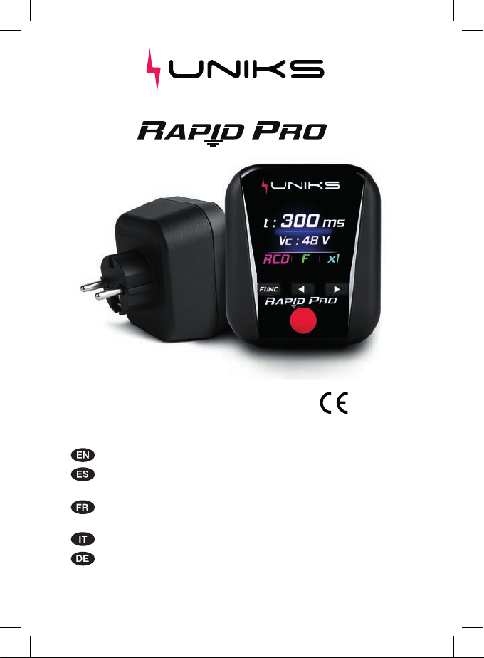
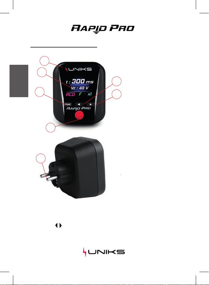
Congratulation for purchase Rapid Pro, the first multifunction tester in the shape of
a socket tester.It allow the test of electrical system according the IEC standard as
the common installation tester do.In addition to the TRMS Voltage measurement
and the Socket Tester features allow Installation test to be performed from anyone
( RCD, LOOP L-PE ) in according to IEC61557-3 and IEC61557-6. Super bright color
Display TFT 1,77” With internal memory for store results. SuperCap technology let
the instruments turn on even when disconnected from the socket
SAFETY and WARNINGS
High Voltage Danger: risk of electric shocks
Aenon: Follow the instrucons given in the manual; improper use
could cause damage to the instrument or create dangerous situaons for
the operator.

5
ENGLISH
GENERAL DESCRIPTION
Rapid Pro execute the following test:
1. VOLT and Socket Test (Correct wiring of Plug)
2. Voltage measurement L-N , TRMS
3. Residual Current (RCD) type A, AC and F also in AUTO mode with
CONTACT VOLTAGE measurement
4. Z LOOP (Global earth resistance in TT system and impedance L-Pe
in TN with short circuit current )
5. Short circuit current
6. Voltage harmonics up to 49 th
7. THD% (Total harmonics Distoron)
8. Frequency of the fundamental Harmonics and up to 49 th
Funcon can be selected thorugh the dedicated buon .Sub funcon
features can be selected through the arrow buon for example for
selecng the RCD type or evaluate dierent harmonics. The instruments
is powered from the line and due to the SUPERCAP technology can keep
the power even when disconnected from the line .Fully charged supercap
allow 45 second aer switch o from the line.This allow the user to read
the value aer the RCD is tripped out(with tripping me) or when is
dicult to read the display value
Outcome are always GREEN when the measured value is correct in
according the local regulamentaon or RED when the test is not passed.
In the SOCKET TEST uncorrect value the instruments generate also a
sound allarm.

6
ENGLISH
PRODUCT DESCRIPTION
Buttons description
Funcon buon allow to select the measure. Display shows the following features:
Socket Test / VOLT - RCD - LOOP - Harmonics / Memory.
Arrow buon ,allow to select subparameters for test and read the memory or to
analyze the harmonics value up to 49th. Red buon can start the RCD test or LOOP
Resistance ( no trip RCD).
1
2
3
4
5
6
7
Legend:
1. Anscratch glass
2. Display TFT 1,77”
3. Funcon
4. TEST
5. subfeatures selecon
6. subfeatures selecon
7. SCHUKO plug

7
ENGLISH
VOLT e SOCKET TEST
Fig. 1
Fig. 2 Fig. 3
Legend:
1. Anscratch glass
2. Display TFT 1,77”
3. Funcon
4. TEST
5. subfeatures selecon
6. subfeatures selecon
7. SCHUKO plug
This feature measure Voltage between phase and neutral and test the socket wiring
in according to local requirement.
Operaon
Plug the instruments in the socket and select Voltage
funcon with buon.Voltage between Phase and
Neutral will be shown at display if socket is correctly
wired and voltage contact is <50V (Fig 1) error due
to the uncorrect wiring is shown(Fig 2 e 3). Green bar
indicate every parameter is correct. Frequency can be
shown through buon .
Wiring Error ( bar is Red and
sound allarm)
•Phase - Neutral Reverse
•Phase - Ground Reverse
•Open Neutral
•No Ground
•Voltage contact >50V
Soluon
Adjust the socket wiring
Connect Neutral wire
Check Earth connecon
Dangerous Voltage on mass

8
ENGLISH
RCD x1 , x5
Connect FASTCHECK3020 to the socket and press FUNC in order to select RCD
funcon. Press the buon for select the type of RCD and buon for select the
current (x1,x5) Press RED buon for 3 second for start the measure.
RCD (RESIDUAL CURRENT DEVICE)
Fig. 5
Fig. 4
This feature allow test of RCD according EC/EN 61557-6 with tripping me and
Voltage contact. Test Current of 30 mA is injected through the ground for type A ,
AC and F.
Test Mode:
•x1 I∆n –Test with 30mA
•x5 I∆n –Test with 150mA
•AUTO –Test sequence x1/2 - x1/2 180° - x1 - x1 180° - x5 - x5 180°
Tripping Time is shown on the display and
Green bar means the test is performed
correctly
Vc is the contact Voltage.
If Contact Voltage >50V the RCD tripping test
will be stopped and the bar became RED
Display shown tripping me is higher than the
limit standard and Red Bar means outcome
NOT OK (Fig 5).
Vc is the Contact Voltage.

9
ENGLISH
RCD (RESIDUAL CURRENT DEVICE)
STEP 1
STEP 2
STEP 3
STEP 4
STEP 5
STEP 6
I∆n x1 0°
I∆n x1 180°
I∆n x5 0°
I∆n x5 180°
I∆n x1/2 0°
I∆n x1/2 180°
OK IF <300 ms
OK IF <300 ms
OK IF <40 ms
OK IF <40 ms
OK IF >1000 ms
OK IF >1000 ms
Fig. 7
Fig. 6
AUTO funcon
Plug the instrument in the socket and press FUNC for select RCD funcon. Press
arrow buon for select type of RCD and buon for select funcon AUTO .
Start measuring by pressing the Red buon,The instruments will execute all test in
sequence when you re-arm the RCD and voltage is on.
AUTO mode consist of 6 test in the folowing sequence:
Display Show RCD tripping me in ms. For every
STEPtripping me in ms will be shown. GREEN (Fig
6) if the test and tripping me are conform to local
tripping me regulamentaon.
Value in RED (Fig 7) means the test is not conform
to the local guideline and the test will be stopped.

10
ENGLISH
LOOP FUNCTION
Plug Rapid Pro in the socket and press FUNC button for select LOOP. Press
button for select TT or TN and press button for select TEST STD or LOW.
Press the RED button for 2 second to start the measurement
LOOP
Fig. 8 Fig. 9
The measurament is performed according IEC/EN61557-3 it measure impedance
between Phase and Ground withouth RCD trip. Test Mode:
•TT Measure Earth Resistance (Ω) and Contact Voltage (V) Fig.8
•TN Measure Impedance Z L-Pe (Ω) and Ipsc prospecve short circuit current
(A) Fig.9
•Std Test with 15mA nominal current
•Low Test with 6mA. Use this setup if during the test the RCD trip due to the
presence of leackage current in the electric system under test.
During the LOOP measurement, if the SUPER CAP is not
fully charged, the Display may switch o or decrease the
intensity, however the measurement will be performed and
shown at the end.

11
ENGLISH
LOOP TT e TN
Re Rt
L
N
Pe
RCD
Rt
L
N
Pe
TERRA
BT MT
BT MT
RCD
FUSE
Rt ≤ Vc
I∆n
Re Rt
L
N
Pe
RCD
Rt
L
N
Pe
TERRA
BT MT
BT MT
RCD
FUSE
TT SYSTEM
TN-S SYSTEM
Z line - PE impedance measurement in TT system
Z: Global Earth Resistance
Vc: Contact Voltage
NOTA: Limit for earth ground resistance is dened as:
Vc:Contact Voltage Limit (50V o 25V)
I∆n: Nominal RCD current
Impedance measurement Zs L-pe in TN system
Z: Fault Ground Impedance L-Pe
Ipsc: Prospecve short circuit current (for check correct sizing of MCB or FUSE
protecng the system)

12
ENGLISH
HARMONICS FUNCTION
Plug Rapid Pro in to the socket and choose Har function by pressing FUNC button.
Press for select harmonics higher or button for select back to h1
Is it possible to disconnect FASTCHECK3020 from the supply power for easilly read
and analyze the measurements unl the SUPERCAP discharge (60 second when fully
charged).
HAR VOLTAGE HARMONICS
Fig. 10 Fig. 11
This funcon allow to check Voltage quality and harmonics up to 49th .
TEST MODE:
•Fund Fundamental harmonic h1 (red), his frequency (~50Hz) and THD%
Indicate total harmonic distorsion of voltage supply (Fig. 10).
•h2....50 Show VOLTAGE value TRMS of selected harmonics (red), his
frequency and percentage (%) compared to h1 Fundamental 50Hz (Fig. 11)

13
ENGLISH
MEM Memory / REPORT
Fig. 12
Fig. 13
The instruments automacally save RCD and LOOP measurement in MEM area.
Press FUNC buon for enter MEM page. Press buon or for move through the
saved data or press simultaneously to clear the memory.
It will be possible to store 64 consecuve measures.
By pressing the RED buon you can generate a QR CODE for the generaon of
REPORTS (Fig. 12). The 64 posions can be organized in chronological order. The last
measurement will always be saved in the rst free CELL in ascending order (1… 64)..
surement for day of use . Last measure will be saved in the rst Memory Slot free
(1…64) or in the last cell if memory is full scaling all the other.
REPORT CREATE
Press the RED buon to generate the QR CODE.
Scan the QR CODE with your smartphone using
the RAPID PRO REPORT APP.
All saved measurements will be included in a
REPORT with the possibility of exporng in pdf
or csv
Download the RAPID PRO APP for iOS and
Android systems.
MEMORY
Column N ° indicates the measurement number
(Fig. 13).
The FUNC column indicates the saved
measurement with its sengs.
The Value column indicates the outcome of the
measurement.
The result of the RCD measurement is indicated:
GREEN if the result is OK
RED if the result is NO OK.

14
ENGLISH
IEC/EN61557-6
IEC/EN61557-3
TECHNICAL DATA
Voltage L-Pe 190÷265V - Frequency 50Hz 5%
RCD
LOOP (Fault Loop Impedance)
Voltage L-Pe 190÷265V - Frequency 50Hz 5% Min.Value > 0,3 Ω
Std Current test 15mA
LOW Test Current 6mA
RANGE (Ω) Resoluon (Ω) Accuracy
Type(RCD) RISOLUZIONE PRECISIONE
Open Ground or Neutral,Phase/Neutral Phase/Ground reverse - Vc>50V
Socket Test Voltage L-N 190÷265V
0.01 ÷ 9.99
10 ÷ 99.9
100 ÷ 999
AC , A , F
Time
Crest Factor 1,5 ; Frequency 42 ÷ 69.0 Hz 5%
Voltage AC TRMS (Phase-Neutral)
RANGE (V) Resoluon (V) Accuracy
1
0.01
0.1
1
Voltage L-N 190÷265V - Frequency 50Hz 5%
Frequency
RANGE (Hz) Resoluon (Hz) Accuracy
42 ÷ 69 0.1
1 ÷ 50th Harmonics <0.8V will not be shown
Voltage Harmonics
RANGE (V) Resoluon(V) Accuracy
0,8 ÷ 256 0.1
(5.0% + 8 dgt)
(5.0% + 8 dgt)
(5.0% + 8 dgt)
(0.0% + 5%I∆n)
(2 ms + 2 dgt)
<0.1I∆n
0.1 ms
(8.0% + 12 dgt)
(1.0% + 3 dgt)
(2.0% + 1 dgt)
(3.0% + 5 dgt)
190 ÷ 265

15
ENGLISH
TECHNICAL SPECIFICATION
INPUT:
Overvoltage Category:
Max Voltage input:
Maximum absorbed current:
Input voltage uctuaon
INPUT:
Measures Guidelines:
Safety Guidelines :
EMC:
Display and Memory:
Display:
Memory Slot:
Enviromental Specicaon:
Altude:
Reference Temperature:
Operaonal Temperature:
Maximum Humidity:
Stock temperature:
Stock Humidity:
Polluon degree:
Mechanical Characteriscs:
Size:
Weight:
CAT III 300V verso terra
265V AC
<25mA
10%
IEC/EN61557-3
IEC/EN61557-6
IEC/EN61010-1
IEC/EN61010-2-030
IEC/EN61326-1
TFT 1,77” Display
64
0 ÷ 2000 m
23°C ÷ 5°C
5°C ÷ 40°C
<80%RH
20°C ÷ 60°C
<80%RH
2
81,5 x 70 x 83) mm
110gr

16
ENGLISH
ADAPTERS
The Rapid Pro can be connected to various adapters on the market such as
extension cords or adapters for sockets other than the Schuko (Fig. 14).
The use of an extension cord can help the operator perform LOOP or RCD
measurements in environments where it is dicult to reach the socket for tesng.
UNIKS Srl is not responsible for malfunctions due to
adapters. Fig. 14

17
ENGLISH
Use a damp cloth and a small amount of detergent to clean the instrument shell.
Do not use abrasive or chemical solvents.
Maintenance
The instrument should be recycled as electronic waste

18
ESPAÑOL
ÍNDICE
INTRODUCCIÓN.......................................................... 19
SEGURIDAD y ADVERTENCIAS .................................... 19
DESCRIPCIÓN GENERAL.............................................. 20
DESCRIPCIÓN DEL PRODUCTO.................................... 21
TENSIÓN Y PRUEBA DE BASE DE ENCHUFE................ 22
DIFERENCIAL............................................................... 23
BUCLE ......................................................................... 25
BUCLE TN - TT............................................................. 26
ARMONÍCOS............................................................... 27
MEM MEMORIA / INFORME ...................................... 28
DATOS TÉCNICOS........................................................ 29
ADAPTADOR ............................................................... 31
MANTENIMIENTO....................................................... 32

19
ESPAÑOL
INTRODUCIÓN
La tensión máxima de entrada es de 265 V. No conecte el instrumento a una tensión superior.
Si no se respetan estas directrices, pueden producirse riesgo de descarga eléctrica peligrosa
Este producto ha sido fabricado siguiendo la norma IEC/EN61010-1,
directrices para comprobadores de seguridad en instalaciones. Siga este
manual de usuario para evitar daños en los instrumentos.
•No realice mediciones en entornos húmedos o con mucha humedad.
•Evite medir en lugares altamente inamables.
•Evite el contacto con el circuito bajo prueba si no está midiendo.
•Evite el contacto con partes metálicas que puedan estar bajo tensión.
•Si los instrumentos parecen rotos o dañados, evite ulizarlos para medir.
Alto voltaje Peligro: riesgo de descargas eléctricas
Atención: Siga las instrucciones del manual; un uso inadecuado podría dañar
el instrumento o crear situaciones peligrosas para el operador
Enhorabuena por la compra de Rapid Pro, el primer comprobador multifunción en
forma de enchufe. Permite comprobar el sistema eléctrico según la norma IEC, al
igual que los comprobadores de instalaciones habituales. Además de la medición
de tensión TRMS y las funciones del comprobador de tomas, permite realizar
pruebas de instalación desde cualquier dispositivo ( RCD, LOOP L-tierra ) de
acuerdo con IEC61557-3 y IEC61557-6.
Pantalla a color TFT de 1,77” con memoria interna para almacenar los resultados.
La tecnología Super Cap permite que los instrumentos se enciendan incluso cuando
están desconectados de la toma de corriente.
SEGURIDAD y ADVERTENCIAS

20
ESPAÑOL
DESCRIPCIÓN GENERAL
Rapid Pro ejecuta las siguientes pruebas:
1. Prueba de voltaje y enchufe (cableado correcto del enchufe).
2. Medida de tensión L-N , TRMS
3. Corriente residual (RCD) po A, AC y F también en modo AUTO con
medición de TENSIÓN DE CONTACTO
4. Z LOOP (Resistencia global de erra en sistema TT e impedancia
L-Pe en TN con corriente de cortocircuito )
5. Corriente de cortocircuito
6. Armónicos de tensión hasta 49
7. THD% (Distorsión armónica total)
8. Frecuencia de los armónicos fundamentales y hasta 49º.
La función se puede seleccionar mediante el botón correspondiente.
Las funciones secundarias pueden seleccionarse mediante el botón de
echa, por ejemplo, para seleccionar el po de disposivo de corriente
residual o evaluar diferentes armónicos. Por ejemplo, para seleccionar el
po de diferencial o evaluar diferentes armónicos. Los instrumentos se
alimentan de la línea y, gracias a la tecnología SUPERCAP, puede mantener
la alimentación incluso desconectado de la línea. El supercondensador
completamente cargado permite una autonomía de 45 segundos tras la
desconexión de la línea. Esto permite al usuario leer el valor después de
que el diferencial se desconecte (con empo de desconexión) o cuando es
dicil leer el valor de la pantalla.
Los resultados son siempre VERDES cuando el valor medido es correcto
de acuerdo con la normava local o ROJO cuando no se supera la prueba.
En el caso de un valor incorrecto en el test de la toma de enchufe, el
instrumento genera también un sonido de alarma.
Other manuals for RAPID PRO
1
Table of contents
Languages:
Other Uniks Test Equipment manuals