manuals.online logo
Brands
  1. Home
  2. •
  3. Brands
  4. •
  5. Larson Electronics
  6. •
  7. Accessories
  8. •
  9. Larson Electronics EXP-MS-30W-N4X-SFC User manual

Larson Electronics EXP-MS-30W-N4X-SFC User manual

1
2
EXP-MS-30W-N4X | Larson Electronics, LLC Page 1 of 4
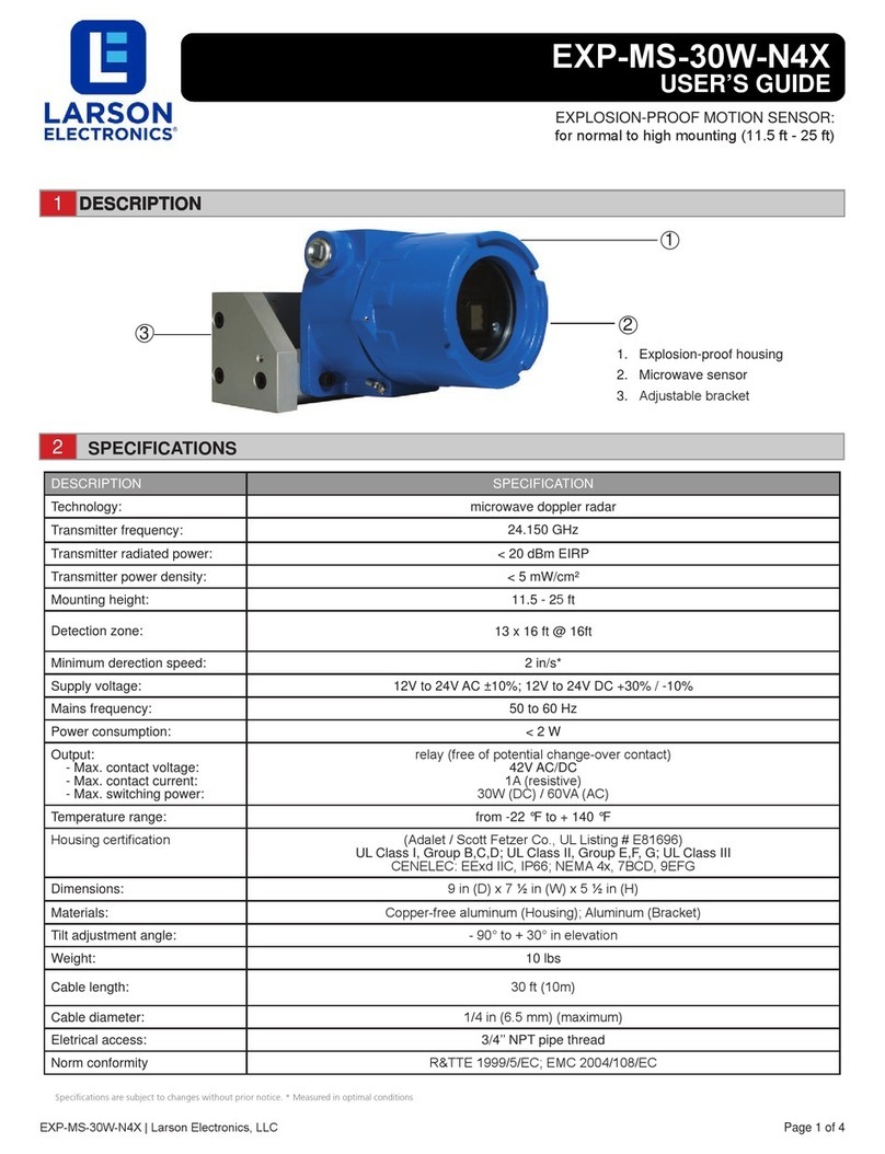
SPECIFICATIONS
DESCRIPTION SPECIFICATION
Technology: microwave doppler radar
Transmitter frequency: 24.150 GHz
Transmitter radiated power: < 20 dBm EIRP
Transmitter power density: < 5 mW/cm²
Mounting height: 11.5 - 25ft
Detection zone: 13 x 16 ft @ 16ft
Minimum derection speed: 2 in/s*
Supply voltage: 12V to 24V AC ±10%; 12V to 24V DC +30% / -10%
Mains frequency: 50 to 60 Hz
Power consumption: < 2 W
Output:
- Max. contact voltage:
- Max. contact current:
-Max. switching power:
relay (free of potential change-over contact)
42V AC/DC
1A (resistive)
30W (DC) / 60VA (AC)
Temperature range: from -22 °F to + 140 °F
Housing certication (Adalet / Scott Fetzer Co., UL Listing # E81696)
UL Class I, Group B,C,D; UL Class II, Group E,F, G; UL Class III
CENELEC: EExd IIC, IP66; NEMA 4x, 7BCD, 9EFG
Dimensions: 9 in (D) x 7 ½ in (W) x 5 ½ in (H)
Materials: Copper-free aluminum (Housing); Aluminum (Bracket)
Tilt adjustment angle: - 90° to + 30° in elevation
Weight: 10 lbs
Cable length: 30 ft (10m)
Cable diameter: 1/4 in (6.5 mm) (maximum)
Eletrical access: 3/4’’ NPT pipe thread
Norm conformity R&TTE 1999/5/EC; EMC 2004/108/EC
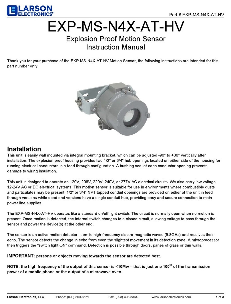
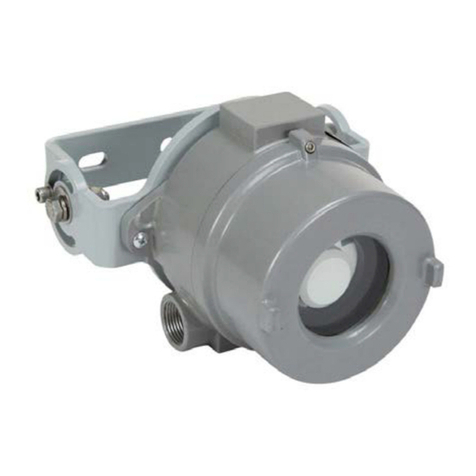
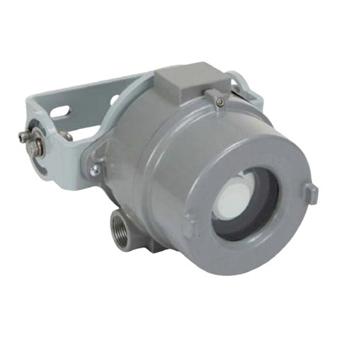
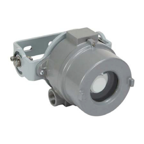
EXP-MS-30W-N4X-SFC
USER’S GUIDE
EXPLOSION-PROOF MOTION SENSOR:
for normal to high mounting (11.5 ft - 25 ft)
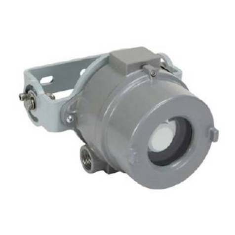
1. Explosion-proof housing
2. Microwave sensor
DESCRIPTION
DESCRIPTION
DESCRIPTION
DESCRIPTION
Specifications are subject to changes without prior notice. * Measured in optimal conditions
EXP-MS-30W-N4X
Mounting height: 16 ft
COM
NO
NC
12-24 V
AC-DC
RED
BLACK
WHITE
GREEN
YELLOW
Connect the wires to the
door controller. Choose
between NO and NC
contact.
EXP-MS-30W-N4X | Larson Electronics, LLC Page 2 of 4
INSTALLATION TIPS
-The sensor must be rmly fastened in order not to vibrate.
-The sensor must not be placed directly behind a panel or any kind of material.
-The sensor must not have any object likely to move or vibrate in its sensing eld.
-The sensor must not have any uorescent lighting in its sensing eld.
WIRING
DETECTION FIELD DIMENSIONS
•When the power is turned ON, the red and green LEDs ash for few seconds.
•During a detection the red LED lights illuminates.
•During conguration, the red LED ashes a number of times corresponding to the parameter being changed (see
next table). The green LED ashes a number corresponding to its setting.
EXP-MS-30W-N4X | Larson Electronics, LLC Page 3 of 4
POSSIBLE SETTINGS BY REMOTE CONTROL
1-6
-75°
-60°
-45°
Choose the right detection lter for your application with the remote control
Value recommendations according to angle and height:
Detection of all targets
(pedestrians and parallel trafc are detected)
1 = no specic lter
2 = lter against disturbances
(recommended in case of vibrations, rain etc.)
Detection only of vehicles moving*
(pedestrians and parallel trafc are not detected + disturbances are ltered)
* The vehicle detection lter increases the response time of the sensor.
Always check if the chosen
value is optimal for the appli-
cation.
The object size and nature
can inuence the detection.
23 ft - 11.5 ft 8 ft
3
4
5
DETECTION FILTER (REJECTION MODE)
3
4
4
LED SIGNALS
POSSIBLE SETTINGS BY PUSH BUTTONS
(7)
(0)
(1)
(2)
(1)
TO START OR END AN ADJUSTMENT SESSION, press and hold either push button until the LED ashes or stops
ashing.
1FIELD SIZE
Parameter number
2HOLD-OPEN TIME
3OUTPUT CONFIGURATION
4DETECTION MODE
5DETECTION FILTER
Value (factory values)
TO SCROLL THROUGH THE
PARAMETERS, press
the right push button.
TO CHANGE THE VALUE
OF THE CHOSEN
PARAMETER, press the left
push button.
TO RESET TO FACTORY VALUES, press and hold both push buttons until both LEDs ash.
FIELD SIZE
OUTPUT
CONFIGURATION
DETECTION MODE
FACTORY VALUES RESETTING TO FACTORY VALUES:
DETECTION FILTER
RELAY HOLD TIME
XXS XS S > > > > L XL XXL
0.5 s 1 s 2 s 3 s 4 s 5 s 6 s 7 s 8 s 9 s
3 4 5 6
12
P
A
A = active output
(relay active when detection)
P = passive output
(relay active when no detection)
uni
AWAY
bi = two-way detection
uni = one-way detection towards sensor
uni AWAY = one-way detection away from sensor
bi uni
CHECKING A VALUE
Red
Red
X
Green Off
X = number of flashes = value of parameter
TROUBLESHOOTING
1
1
2
3
4
5
1
2
1
2
1
1
2
3
1
The sensor power is off. Check the wiring and the power supply.
The sensor cycles in
and out of detection
The LED
ashes quickly
after unlocking.
The sensor does not
respond to the remote
control
Improper output
conguration on the sensor.
The sensor is disturbed by
vibration, a moving object, or
electrical noise from nearby
environment.
The sensor needs an access
code to unlock.
The remote control batteries
are weak or improperly
installed.
Check the output conguration setting on each
sensor connected to the user equipment.
Check the batteries and change them
if necessary.
Make sure the detection mode is unidirectional.
Increase the detection lter value.
Sensor appears
unresponsive
Make sure the sensor is xed properly.
Make sure the detection mode is unidirectional.
Increase the tilt angle.
Increase the detection lter value.
Reduce the eld size.
Enter the right access code.
If you do not know the access code, cut the power
supply and restore it to access the sensor and
change the access code or delete it.
Change the antenna angle.
Decrease the eld size.
Increase the detection lter value.
The sensor goes
into detection for no
apparent reason
The sensor detects raindrops
or vibrations.
In highly reective
environments, the sensor
detects objects outside of its
detection eld.
Discrepency
between sensor state
and sensor output
SAFETY INSTRUCTIONS
The manufacturer of the end-user equipment is responsible for carrying out a risk assessment and installing the sensor and the end-user equipment in
compliance with applicable national and international regulations and standards of the end-user equipment.
Only trained and qualified personnel may install and setup the sensor.
The warranty is void if unauthorized repairs are made or attempted by unauthorized personnel.
Only for EC countries: According the European Guideline 2012/19/EU for Waste Electrical and Electronic Equipment (WEEE)
Customer Service: 1-800-369-6671 | General Questions: Sa[email protected]
EXP-MS-30W-N4X | Larson Electronics, LLC Page 4 of 4
ACCESS CODE
If you do not know the access code, cut and restore the power
supply. During 1 minute, you can erase an unkown access code:
SAVING AN ACCESS CODE:
DELETING AN ACCESS CODE:
The access code (1 to 4 digits) is recommended to set sensors installed close to each other.
ERASE AN UNKOWN ACCESS CODE:
Once you have saved an access code, you always need to enter this code to unlock the sensor.
Other Larson Electronics Accessories manuals

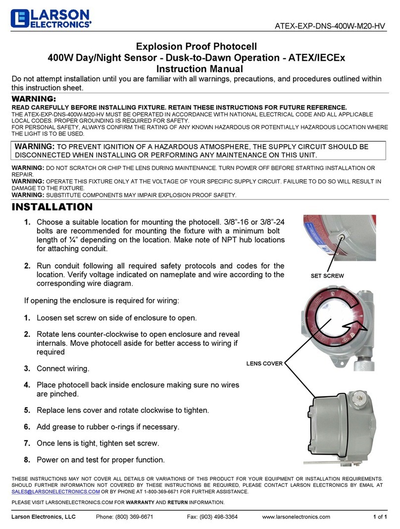
Larson Electronics ATEX-EXP-DNS-400W-M20-HV User manual

Larson Electronics

Larson Electronics ATEX-EXP-DNS-400W-M20-HV User manual

Larson Electronics EXP-MS-N4X-AT-HV-V5 User manual

Larson Electronics

Larson Electronics EXP-MS-N4X-AT-HV-V5 User manual

Larson Electronics EPLTS-T8 User manual

Larson Electronics

Larson Electronics EPLTS-T8 User manual

Larson Electronics EXP-MS-N4X-AT-HV-V6 User manual

Larson Electronics

Larson Electronics EXP-MS-N4X-AT-HV-V6 User manual

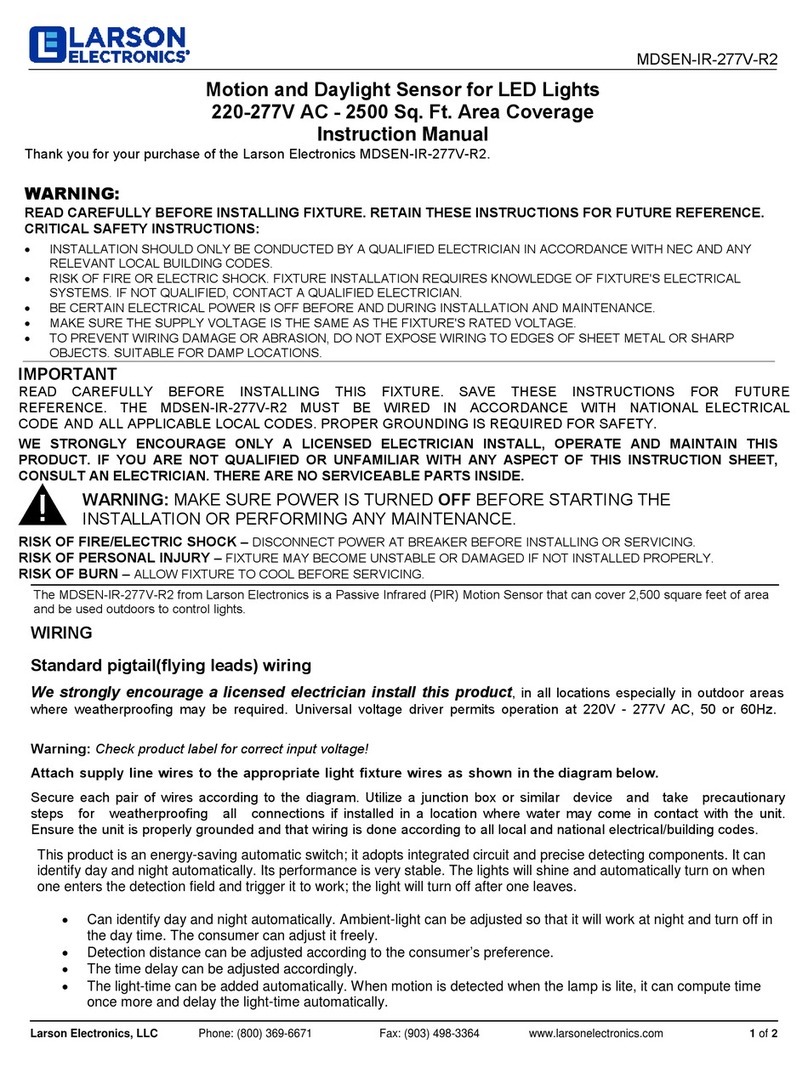
Larson Electronics MDSEN-IR-277V-R2 User manual

Larson Electronics

Larson Electronics MDSEN-IR-277V-R2 User manual

Larson Electronics XLE-PA-IP20-CS.50-50A-3PH-250V-3P4W-B User manual

Larson Electronics

Larson Electronics XLE-PA-IP20-CS.50-50A-3PH-250V-3P4W-B User manual

Larson Electronics EXP-AKC-MS-N4X-AT-LV-12V User manual

Larson Electronics

Larson Electronics EXP-AKC-MS-N4X-AT-LV-12V User manual

Larson Electronics IND-HL-HDB-FUVC-EX-1L-120V-15C User manual

Larson Electronics

Larson Electronics IND-HL-HDB-FUVC-EX-1L-120V-15C User manual

Larson Electronics EXP-MS-30W-N4X User manual

Larson Electronics

Larson Electronics EXP-MS-30W-N4X User manual

Larson Electronics EXP-DNMS-N4X-AT-HV User manual

Larson Electronics

Larson Electronics EXP-DNMS-N4X-AT-HV User manual

Larson Electronics SLEDB-110V-30C-XMS User manual

Larson Electronics

Larson Electronics SLEDB-110V-30C-XMS User manual

Larson Electronics EXP-MS-N4X-AT-LV User manual

Larson Electronics

Larson Electronics EXP-MS-N4X-AT-LV User manual

Larson Electronics EXP-MS-N4X-AT-HV User manual

Larson Electronics

Larson Electronics EXP-MS-N4X-AT-HV User manual

Larson Electronics IND-TBL-BX-R13-UVC-120V User manual

Larson Electronics

Larson Electronics IND-TBL-BX-R13-UVC-120V User manual

Larson Electronics SLEDB-277V-30C-XMS User manual

Larson Electronics

Larson Electronics SLEDB-277V-30C-XMS User manual

Popular Accessories manuals by other brands

Pepperl+Fuchs NCB4-12GM40-N0-V1 instruction manual

Pepperl+Fuchs

Pepperl+Fuchs NCB4-12GM40-N0-V1 instruction manual

Pilgrim Zoe user manual

Pilgrim

Pilgrim Zoe user manual

Sunbeam Sleep warm. Sleep well. user manual

Sunbeam

Sunbeam Sleep warm. Sleep well. user manual

LEGRAND 0 942 50 quick start guide

LEGRAND

LEGRAND 0 942 50 quick start guide

Hexagon m&h IRP40.50 operating instructions

Hexagon

Hexagon m&h IRP40.50 operating instructions

Panasonic MAZDxxxG Series Specifications

Panasonic

Panasonic MAZDxxxG Series Specifications

IFM PN78 Series operating instructions

IFM

IFM PN78 Series operating instructions

JCI 134 user manual

JCI

JCI 134 user manual

Omron F3S-TGR-SB - datasheet

Omron

Omron F3S-TGR-SB - datasheet

Lippert Components Solera Classic Awning owner's manual

Lippert Components

Lippert Components Solera Classic Awning owner's manual

MRMC MRMC-2168-00 quick start guide

MRMC

MRMC MRMC-2168-00 quick start guide

KitchenAid KSM1APC manual

KitchenAid

KitchenAid KSM1APC manual

QSC Q-SYS PS-1600H user manual

QSC

QSC Q-SYS PS-1600H user manual

Nyce Control NCZ-3011 user guide

Nyce Control

Nyce Control NCZ-3011 user guide

Pillar UniFoiler 3000 Operator's manual

Pillar

Pillar UniFoiler 3000 Operator's manual

Roland VS4S-1 owner's manual

Roland

Roland VS4S-1 owner's manual

Orno OR-CR-254 manual

Orno

Orno OR-CR-254 manual

PCB Piezotronics M101A04 Installation and operating manual

PCB Piezotronics

PCB Piezotronics M101A04 Installation and operating manual

manuals.online logo
manuals.online logoBrands
  • About & Mission
  • Contact us
  • Privacy Policy
  • Terms and Conditions

Copyright 2025 Manuals.Online. All Rights Reserved.