LaserPro Explorer User manual
Explorer
Beam Alignment
Remember to always wear safety glasses while doing any open beam tests.
Copyright Koser Enterprises, Inc 2006
Member of the LaserProNA.com group
Rev 1.00003
www.LaserProNA.com
NA
LaserPro Dealers of North America

This document will show you how to check and align your Explorer. The first thing to do is toLaserPro
check the alignment. Briefly the logic is to have a perfectly straight beam path from Mirror 2
(Back top left) to mirror 3 (Left end of X axis). From mirror 3 to mirror 4 (the one in the lens carriage).
Mirror 0 is for the red beam. Mirror 1 only controls where the beam hits the lens. If mirror 1 is adjusted
incorrectly you may have beveled edges when vector cutting in x or y.
If beam adjustment on Mirror 2 is necessary it may require that the you unfasten the lid, and shift it to
the right. Please note when doing this the lid will be unstable. Take care not to bump or kock it in
such a way to cause it to fall off the Explorer. When Moving the X-Axis arm form P1 to P2 raise the left
end of the lid and move the X-Axis to the next position. See Page 4 for photos.
The first step is to check your machines alignment. We will check it in 4 places P1, P2, P3, and P4.
(Diagram 1) Mirror 2
Mirror 3
P1
P2
P3 P4
Mirror 4
Back of Explorer
To start place a piece of tan masking tape, transfer tape, or small white label to back of mirror 3’s
housing. (Cover the hole the laser beam enters to get to mirror 3)
Turn on the machine while holding down the Auto Focus key on the Control Panel.
Remember to always wear safety glasses while doing any open beam tests. 1
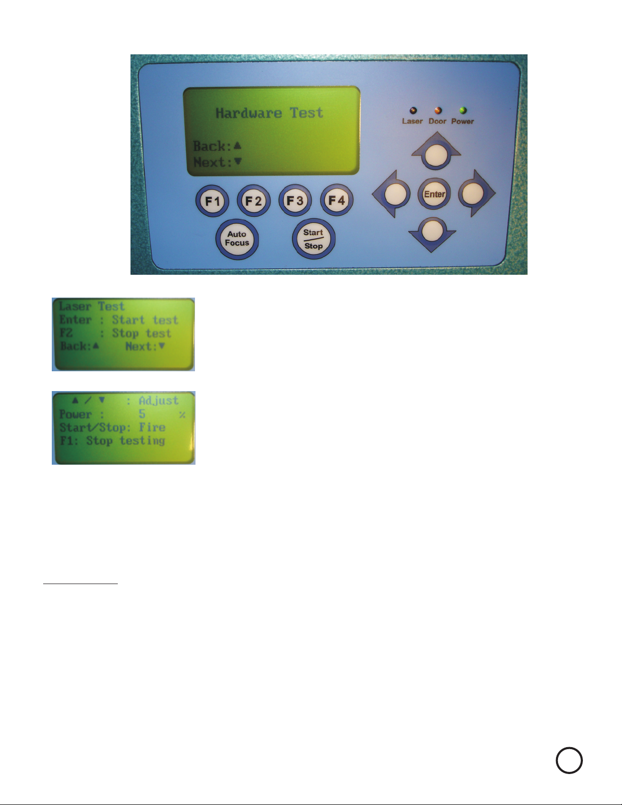
After the unit initialize the Display will look like this.
Press the Up Arrow until the display looks like this.
It will say Laser Test
Press Enter and the display looks like this.
Power should now read 5%. High wattage laser may need
to be lowered to 4 or 3%. Use the Up and Down arrows as
required to adjust the power. In general you want the power
to be strong enough to burn but low enough to make the
mark very light.
You are now ready to check your beam alignment.
Position the X axis in PI (Diagram 1 on page 2) The X axis should be pushed all the way back.
Close the Lid.
Pull the x axis arm toward you and look at the back of Mirror 3. There should be a small brown/black
burn mark. If there is not repeat above until you burn a small spot. If you burn a big spot you
will need a new piece of tape and repeat again.
Press the START key fo about a second, or less. A small amount of smoke should be seen.
Orange
Remember to always wear safety glasses while doing any open beam tests. 2

Back Side of Mirror 3
Small burn mark
Figure 2
Position X axis to P2 (Bring it all the way forward)
Put a small pen mark to the side of this dot so you will know
which dot was fired first.
Repeat step in on previous page to create second dot.
If the dots are on top of each other you are done with mirror 2.
Please go to page 6 for basics of beam alignment read the
directions on how to do all but you can skip adjusting Mirror 2’s
Prism Mount
If you have two separate burn marks continue with this page.
Orange
If your dots look something like this you need to adjust mirror 2.
Please note your Red Dot will NOT line up with your burn marks.
Do not attempt to line Red Dot up it will not be in the same
spot as the C02 beam.
1
2Dot 1 is from P1 and 2 is P2.
P1 dot will never move. We need to adjust the dot at P2 to
hit the one from P1.
Remember to always wear safety glasses while doing any open beam tests.
(Place Pen mark just to left of burn mark for later identification as shown)
3

If Mirror 2 requires adjustment you will need to shift the lid several inches to the right.
Remove the 8 screws that hold the lid on. There are two on each side
Remember to always wear safety glasses while doing any open beam tests.
These are the two back screws
Shift lid several inches to the right to expose Mirror 2’s Prism Mount
4

To do beam alignment you will need to understand a few basics.
1. First closest position to the mirror (P1 or P3) burn mark will not move. (see diagram 1 below)
2. We move P2 to line up on top of P1’s burn, and P4 to line up with P3.
3. The mirrors are aligned by adjusting 2 of the three screws on the prism mount.
One screw moves the beam path up and down while the other is left and right.
5. You need alignment more accurate.as small of a burn mark as possible to make
Place a piece of tape on the back of mirror 3’s sheet metal cover covering up the round hole.
Do a test fire as described in text on page 3.Orange
If your results are not similar to the above you will need to adjust mirror 2 so that only 1 burn mark
and the red dot are visible on the test tape..
4. The red beam will not line up with the burn marks.
However, we adjust the screws and watch the results by following
In other words if the P2 is .06” high and .03” left from P1’s burn, we will
to move the red beam .06” down and .03” right.
adjust the screws
You may find it easier to put a pen mark as far from the red beam as P2 is from P1
Adjust the prism mount to move the red beam so that it is on the target spot you drew.
the red beam’s motion.
Mirror 2
Mirror 3
P1
P2
P3 P4
Mirror 4
Back of Explorer
Remember to always wear safety glasses while doing any open beam tests. 5
(Diagram 1)

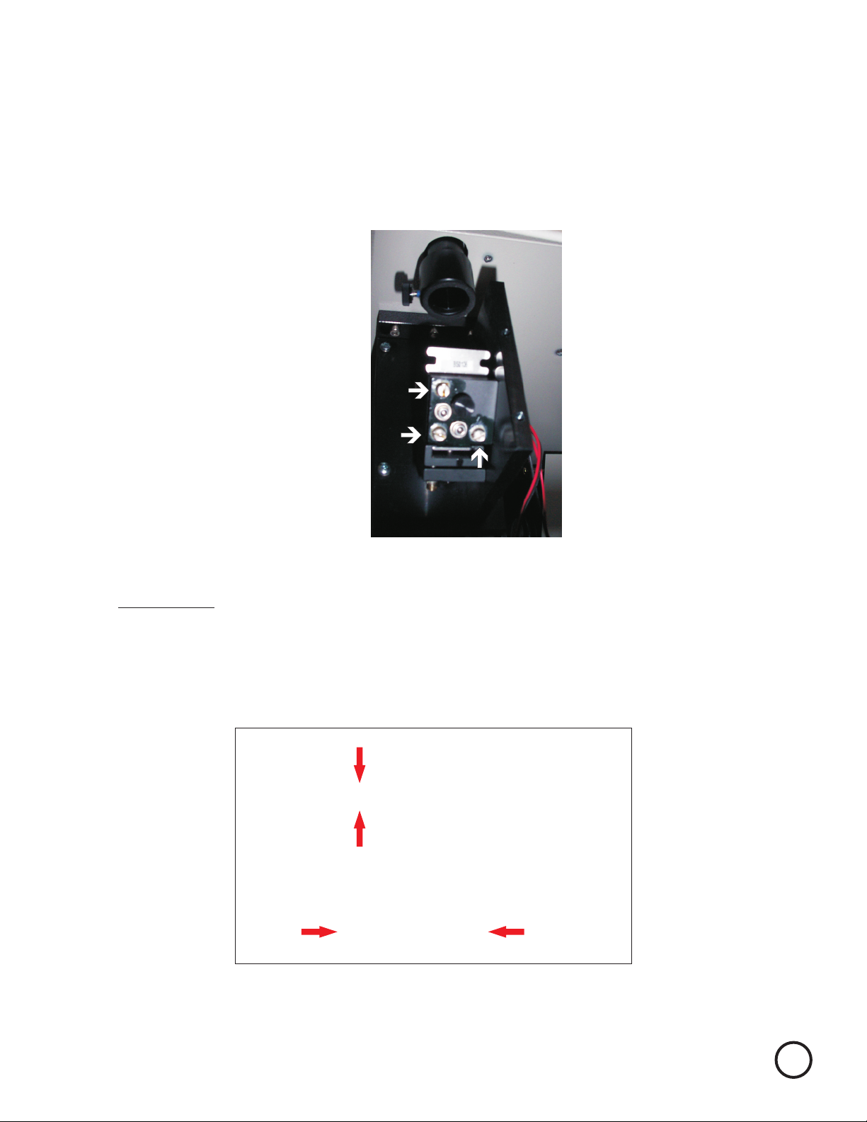
Prism Mount for Mirror 2
(Looking from back of laser with lid off and cover shifted to right)
Screw 1
Pivot Screw do not adjust
Screw 2 Up and Down
Left and Right
Prism Mount
Screw 1
Screw 2
Pivot Screw
Mirror
Once mirror 2 is adjusted we will now repeat all the steps to check and adjust P3 to P4. Do not forget
to remove tape from back of mirror 3. Place your tape on the lens carriage in front of Mirror 4.
As before P3 burn position will not move. Your goal is to get the dot from P4’s firing to line up on top
of P3’s. The difference here is P4 is so far away the beam gets quite large. The burn mark will take
longer to form and the dot is much larger. Burn in P4 1st to make visibility easier. Adjust the prism
mount of mirror 3 by opening up access panel as seen in picture on following page.
Follow the same process as used on mirror 2.
Repeat until P3 falls on top of P4.
You are almost done.
Once you have adjusted the prism mount run the P2 burn again. If it lands on top of your original
P1 burn your done. If not re-adjust to correct. You may wish to use a new piece of tape and run P1
and P2 again. Repeat as often as necessary until P2 line up directly on top of P1
Lock Screw
Lock Screw
Lock Screws must be tightened when adjustments completed. Adjustments should
be made with lock screws snug, they may need to be loosened slightly if adjustment
is made on screws 1 or 2 in a clockwise direction. (Please note tightening up Lock
Screws may affect beam alignment adjust alignment as necessary)
Remember to always wear safety glasses while doing any open beam tests. 6

Mirror 3
Access Panel
Mirror 1
Access Panel
Mirror 3 Prism Mount
1
2
Screw 1 Left and Right
Pivot Screw - do not adjust
Screw 2 Up and Down
Burn Mark From P3 P3 and P4 Burn Mark
Before adjustment
P3 and P4 Burn Mark
After adjustment
Remember to always wear safety glasses while doing any open beam tests. 7
Pivot

Remove the lens form the lens holder. Place a piece of tape on the bottom of the Lens Carriage.
Rub it to leave an impression of the opening.
Make sure you remove the tape from the side of the carriage and fire for 1 second.
Remove the tape from the bottom of the . The burn mark should be near the center
of the impression of the air nozzle opening. (A mirror may be used as well if placed on table below
Lens Carriage to see the orientation of the burn mark.) Looking through the top of the lens carriage
will not give you an accurate location.
You will need to adjust mirror 1 to move the beam to the center. Once completed re-check P1-P4
once more. Any adjustments at this point should be quite minor.
Lens Carriage
To adjust mirror 1 you need to open up Access Panel on the left side of the Explorer See Previous
page for location. Mirror 1 only determines that the beam hits the center of the lens.
Remember to always wear safety glasses while doing any open beam tests.
Burn mark in center of lens carriage bottoms impression.
(Lens is just holding tape for photo)
8
Screw 1
Pivot Screw
Screw 2
Pivot Screw - do not adjust
Adjust screws 1 and 2 only on any prism mount. One will be front to rear, while the other will be
left and right. Mirror 1’s prism mount is displayed below. See bottom image to determine how to
adjust screws 1 and 2.
Adjust the prism mount of Mirror 1 to move the burn mark into the center of the lens carriage.
Screw 1
Clockwise
Counter
Clockwise
Rear of machine
Front of machine
Screw 2
Clockwise Counter Clockwise
Lock Screws must be tightened when adjustments completed. Adjustments should
be made with lock screws snug, they may need to be loosened slightly if adjustment
is made on screws 1 or 2 in a clockwise direction. (Please note tightening up Lock
Screws may affect beam alignment adjust alignment as necessary)
Remember to always wear safety glasses while doing any open beam tests.
Remove the vent plate on the left side, bottom, of the machine and remove the two thumb screws
and the black mirror 1 cover.
9
Table of contents


