manuals.online logo
Brands
  1. Home
  2. •
  3. Brands
  4. •
  5. LATICRETE
  6. •
  7. Plumbing Product
  8. •
  9. LATICRETE Hydro Ban DS-034.0-0412 User manual

LATICRETE Hydro Ban DS-034.0-0412 User manual

F 7.3.12 - 0312 Data Sheets are subject to change without notice. For latest revision, check our website at www.laticrete.com. DS-034.0-0412
1. PRODUCT NAME
LATICRETE®Hydro Ban®Linear Drain
2. MANUFACTURER
LATICRETE International, Inc.
1 LATICRETE Park North
Bethany, CT 06524-3423 USA
Telephone: +1.203.393.0010, ext. 235
Toll Free: 1.800.243.4788, ext. 235
Fax: +1.203.393.1684
Internet: www.laticrete.com
3. PRODUCT DESCRIPTION
LATICRETE Hydro Ban Linear Drain is a low profile linear floor drain
specifically designed for bonded waterproofing installations with
LATICRETE Hydro Ban waterproofing membrane. LATICRETE
Hydro Ban Linear Drain allows for the use of large format tile or stone
installations in a shower with a single plane slope to the drain. The
LATICRETE Hydro Ban Linear Drain can be installed near the wall or
at medial locations in a variety of areas requiring waterproof
applications.
Uses
Interior or exterior
Showers
Industrial, commercial and residential bathrooms and laundries
Kitchens and food processing areas
Terraces, decks and balconies
Advantages
Single slope to drain
Allows for use of large format tile
Tile in grate available to match floor tile
Eliminates pre-slope and primary shower pan
For a faster installation
Made from heavy duty 304 stainless steel provides for long
lasting performance
LATICRETE Hydro Ban waterproof membrane bonds directly to
stainless steel flange edge allowing for faster, easier installation
Suitable Substrates
Concrete
Exterior Glue Plywood (Interior Only)
Cement backer board
Cement mortar beds
Packaging
The LATICRETE Hydro Ban Linear Drain is a two piece drain with a
trough and removable grate. Available in five lengths and two grate
configurations: offset oval in brushed stainless steel and a tile in tray.
The LATICRETE Hydro Ban Linear Drains are available in 24"(61
cm), 32"(81 cm), 36"(91 cm), 48"(122 cm) and 60"(152 cm) lengths.
Limitations
Adhesives/mastics, mortars and grouts for ceramic tile,
pavers, brick and stone are not replacements for waterproofing
membranes. When a waterproofing membrane is required, use
a LATICRETE Hydro Ban (see Section 10 FILING SYSTEMS).
Note: Surfaces must be structurally sound, stable and rigid
enough to support ceramic/stone tile, thin brick and similar
finishes. Substrate deflection under all live, dead and impact
loads, including concentrated loads, must not exceed L/360 for
thin bed ceramic tile/brick installations or L/480 for thin bed
stone installations where L=span length.
Cautions
Consult MSDS for more safety information.
During cold weather, protect finished work from traffic until fully
cured.
All stainless steel surfaces must be clean and free of any dirt,
oil, grease and fingerprints prior to coating with LATICRETE
Hydro Ban.
4. TECHNICAL DATA
Applicable Standard
Code approval per ASME A 112.18-2/CSA B125.2.05 (US and
Canada)
Working Properties
The LATICRETE Hydro Ban Linear Drain series installs per IAPMO
IGC 195-2010. Waterproof using LATICRETE Hydro Ban per TCNA
B422.
5. INSTALLATION
Surface Preparation
All surfaces should be between 40°F (4°C) and 90°F (32°C) and
structurally sound, clean and free of all dirt, oil, grease, laitance,
paint, concrete sealers or curing compounds. Dry dusty concrete
slabs or masonry should be dampened and excess water swept off.
Hydro Ban® Linear Drain
DS-034.0-0412
F 7.3.12 - 0312 Data Sheets are subject to change without notice. For latest revision, check our website at www.laticrete.com. DS-034.0-0412
Installation may be made on a damp surface. Expansion joints shall
be provided through the tile work from all construction or
expansion joints in the substrate. Follow ANSI specification A108.01-
3.7: Requirements for Movement Joints: Preparations by Other
Trades” or TCNA detail EJ-171 “Movement joints-Vertical &
Horizontal”. Do not cover expansion joints with mortar.
Typically Linear Drains should run from sill plate to sill plate (the
width of the shower) against a wall (see ES-B415LD Bonded Corner
Placement). Alternatively they can also be placed in medial locations
(see ES-B415LD Unbonded Medial Placement) or at the shower
entrance. In all locations the waste line for standard size
LATICRETE®Hydro Ban®Linear Drains are in the center of the linear
drain. When installed against a wall the center of the waste line
should be located far enough away from the sill plate to
accommodate wall sheathing and finished tile surface. For 1/2" (12
mm) wall board and 3/8" (9 mm) tile the center of the waste line
should be located 2 1/4" (57 mm) out from the sill plate.
Mortar Bed—Installation over concrete (see ES-B415LD Bonded
Corner Placement and ES-B415LD Unbonded Medial) For a Bonded
mortar bed over concrete installation, before placing mortar, apply a
slurry bond coat made from LATICRETE 254 Platinum or LATICRETE
4237 Latex Additive mixed with LATICRETE 211 Powder. While the
slurry bond coat is wet, spread LATICRETE 3701 Fortified Mortar Bed
and compact well. Bonded mortar beds over concrete shall be 3/4"(19
mm) minimum to 2"(50 mm) maximum. For an unbonded installation
over concrete (see ES-415LD Unbonded Medial) a cleavage
membrane as specified in ANSI A108.02-3.8 should be used in place
of the slurry bond coat. The LATICRETE 3701 Fortified Mortar Bed
should be reinforced with 2" x 2" (50 x 50 mm) reinforcing mesh.
Unbonded Mortar beds over concrete shall be 1-1/4"(32 mm) minimum
to 2"(50 mm) maximum. In both Bonded and Unbonded mortar Bed
installations place enough LATICRETE 3701 Fortified Mortar Bed
where the linear drain will be set to support the bottom and under the
flanges of the drain trough. Minimum height from the flange to the
substrate should be 1-1/2" (37 mm). Make the connection to the waste
line when the drain is set into place using a no hub connection (not
supplied), see installation instructions below. Next place a ribbon of
LATICRETE 3701 Fortified Mortar Bed along the opposite wall to
create a 1/4" (6 mm) per foot slope to the LATICRETE Linear Drain. Fill
the area between the drain and the walls with LATICRETE 3701
Fortified Mortar Bed; screed and compact well. Mortar beds in excess
of 2"(50 mm) thick shall be detailed by the architect per TCNA F112.
Mortar Bed –Installation over Exterior Glue Plywood ( EGP) (see
ES-415LD EGP Bonded Corner Placementl and ES-415LD EGP
Unbonded Medial Placement)
For a bonded mortar bed over EGP installation, before placing
mortar, install a cleavage membrane as specified in ANSI A108.02-
3.8. Expanded metal lath (minimum 2.5 pounds (1.1 kg)/square yard
(0.8 square meters) and complying with ANSI A108.02 3.6) is then
nailed or stapled to the subfloor over the cleavage membrane.
Following the lath spread LATICRETE 3701 Fortified Mortar Bed and
compact well. Bonded mortar beds over EGP shall be 3/4"(19 mm)
minimum to 1 1/2"(38 mm) maximum. For an unbonded installation
over EGP (see ES-415LD EGP Unbonded Medial Placement) install
a cleavage membrane as specified in ANSI A108.02-3.8 and then
spread the LATICRETE 3701 Fortified Mortar Bed. In both bonded
and unbonded mortar bed installations place enough LATICRETE
3701 Fortified Mortar Bed where the linear drain will be set to support
the bottom and under the flanges of the drain trough. Minimum height
from the flange to the substrate should be 1-1/2" (38 mm). Make the
connection to the waste line when the drain is set into place using a
no hub connection (not supplied). Next place a ribbon of LATICRETE
3701 Fortified Mortar Bed along the opposite wall to create a 1/4" (6
mm) per foot slope to the LATICRETE Linear Drain. Fill the area
between the drain and the walls with LATICRETE 3701 Fortified
Mortar Bed; screed and compact well. Mortar beds in excess of 2"(50
mm) thick shall be detailed by the architect per TCNA F112.
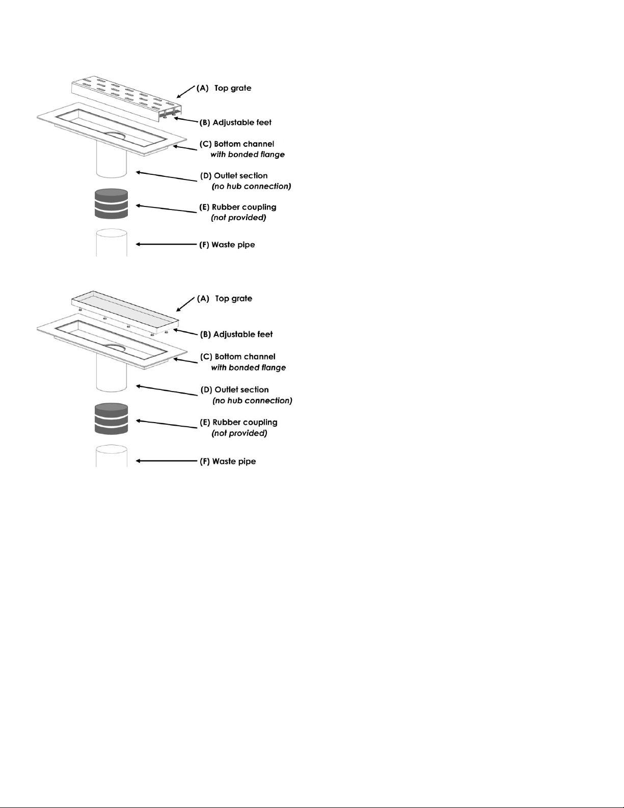
Installation Instructions (Fig. 1)
1. Connect outlet (D) to waste pipe (F) via 2"(50 mm) no hub
connection using a rubber coupling (E) (not provided). Note:
outlet section (D) is 3"(76 mm) long and can be modified for
height adjustment. Grate A has adjustable feet for finer
adjustment (Minimum tile height with thin-set is 3/8"(10 mm),
maximum tile height is 3/4"(19 mm)).
2. Using a LATICRETE 3701 Fortified Mortar Bed set and level
channel (C)
3. Spread LATICRETE 3701 Fortified Mortar Bed, slope 1/4" per
foot (19mm per m) away from drain in a single plane. Note: tile
height should finish 1/16"(1.5 mm) higher than grate height the
tile in the Tile in Drain Grate.
4. When the mortar is dry install backer board per manufacturer’s
instructions. The backer board will sit on the drain flange and
mortar (see ES-B415LD Bonded Corner Placement or ES-
B415LD EGP Bonded Corner Placement).
5. After the backer board has been installed waterproof the
installation using LATICRETE Hydro Ban per instructions in
DS663.0 and 663.5. The stainless steel from the linear drains
needs to be clean and free of any grease, dirt or fingerprints
prior to coating with Hydro Ban. The LATICRETE Hydro Ban
should cover the metal flange on the linear drain trough to the
top of the first radius and extend up the walls and over the entire
mortar bed. If the gap between the linear drain flange and the
wall board is larger than 1/8" (3 mm) it should be filled with a
LATICRETE Polymer Modified Thin-Set e.g. LATICRETE 254
Platinum) or alternatively use 6" (150 mm) wide LATICRETE
Waterproofing/Anti-Fracture Fabric imbedded into the
LATICRETE Hydro Ban around four sides of the linear drain
overlapping the flange and the LATICRETE 3701 Fortified
Mortar Bed. Lap LATICRETE Waterproofing/Anti-Fractrure
Fabric and LATICRETE Hydro Ban liquid up the wall when
adjacent to show¬er wall and over wall board. DO NOT
waterproof the inside walls and bottom of the linear drain
channels.
6. Take measures to protect grate (A) prior to tiling. Keeping the
grate (A) in the channel (C), thin-set and tile on the waterproof
membrane. Ensure tile allows for clearance of grate (A)
removal. Tile finishes 1/16"(1.5 mm) higher than grate or the tile
in the Tile in Drain Grate.
7. If the grate has adjustable feet then adjust grate (A) height with
adjustable feet (B) as needed.
8. When installing the LATICRETE Hydro Ban Linear Tile Drain
Grate (A) will need to be primed with two coats of LATICRETE
Hydro Ban prior to thin-setting the tile into the top grate. The
stainless steel from the linear drains needs to be clean and free
of any grease, dirt or fingerprints prior to coating with Hydro
Ban.
9. When the second coat of LATICRETE Hydro Ban is dry the
installation can be tiled using a LATICRETE polymer fortified
F 7.3.12 - 0312 Data Sheets are subject to change without notice. For latest revision, check our website at www.laticrete.com. DS-034.0-0412
thin-set and grouted with LATICRETE PermaColor™ or
LATICRETE SpectraLOCK PRO Premium Grout.
Fig. 1
Fig. 2
Instructions to make a drain waste line connection with no
access to tighten rubber coupling. Cut the 2" (50 mm) waste line
so the drain, a 2" (50 mm) rubber coupling, a 4" (100 mm) length of
plastic pipe (plastic pipe material should match waste line and plastic
coupling material) and 2" (50 mm) plastic coupling can be added to
the drain outlet. Cement a 2" (50 mm) plastic coupling to the 4" (100
mm) length of the 2" (50 mm) diameter plastic pipe using the
appropriate cement for either PVC or ABS. Attach the rubber
coupling to the linear drain outlet and the 4" (100 mm) length of 2"
(50 mm) diameter plastic pipe. Tighten hose clamps on 2" (50 mm)
rubber coupling. The final connection is made when the linear drain
is installed by cementing the free end of the 2" (50 mm) diameter
coupling to the waste line.
Cleaning
Clean tools and tile work with water while the LATICRETE products
are fresh.
6. AVAILABILITY AND COST
Availability
LATICRETE®and LATAPOXY®materials are available worldwide.
For Distributor information:
Toll Free: 1.800.243.4788
Telephone: +1.203.393.0010
For on-line distributor information, visit LATICRETE at
www.laticrete.com
Cost Contact a LATICRETE Distributor in your area.
7. WARRANTY
See 10. FILING SYSTEM:
DS 230.13: LATICRETE Product Warranty
DS 025.0: LATICRETE 25 Year System Warranty
DS 230.99: LATICRETE Lifetime Warranty
8. MAINTENANCE
LATICRETE and LATAPOXY grouts require routine cleaning with a
neutral pH soap and water. All other LATICRETE and LATAPOXY
materials require no maintenance but installation performance and
durability may depend on properly maintaining products supplied by
other manufacturers.
9. TECHNICAL SERVICES
Technical assistance
Information is available by calling
Toll Free: 1.800.243.4788, ext. 235
Telephone: +1.203.393.0010, ext. 235
Fax: +1.203.393.1948
Technical and safety literature
To acquire technical and safety literature, please visit our website at
www.laticrete.com.
10. FILING SYSTEM
Additional product information is available on our website at
www.laticrete.com. The following is a list of related documents:
DS 230.13: LATICRETE Product Warranty
DS 025.0: LATICRETE 25 Year System Warranty
DS 230.99: LATICRETE Lifetime Warranty
DS 663.0: LATICRETE Hydro Ban®
DS 230.1: LATICRETE 4237 Latex Additive
DS 677.0: LATICRETE 254 Platinum
DS 239.0: LATICRETE 211 Powder
DS 100.0: LATICRETE 3701 Fortified Mortar Bed
DS 663.5: LATICRETE Hydro Ban How to Instructions
F 7.3.12 - 0312 Data Sheets are subject to change without notice. For latest revision, check our website at www.laticrete.com. DS-034.0-0412

Popular Plumbing Product manuals by other brands

Danze D225558 manual

Danze

Danze D225558 manual

Kohler K-12286 Installation and care guide

Kohler

Kohler K-12286 Installation and care guide

Blanco 1-3/4 Reverse Bowl Undermount 510-888R Specifications

Blanco

Blanco 1-3/4 Reverse Bowl Undermount 510-888R Specifications

Quooker Scale Control Plus manual

Quooker

Quooker Scale Control Plus manual

Signature Hardware 948947 quick start guide

Signature Hardware

Signature Hardware 948947 quick start guide

Blanco BlancoMilano 157-092 Specification sheet

Blanco

Blanco BlancoMilano 157-092 Specification sheet

Haas 3952 manual

Haas

Haas 3952 manual

Hans Grohe Raindance Select E 150 3jet 26551 0 Series Assembly instructions

Hans Grohe

Hans Grohe Raindance Select E 150 3jet 26551 0 Series Assembly instructions

American Standard 3275 Specifications

American Standard

American Standard 3275 Specifications

Moen 6500 Illustrated Parts

Moen

Moen 6500 Illustrated Parts

Signature Hardware PENTERO quick start guide

Signature Hardware

Signature Hardware PENTERO quick start guide

Moen CA87011 Series manual

Moen

Moen CA87011 Series manual

Emerson PENBERTHY K3 Series Installation, operation and maintenance instructions

Emerson

Emerson PENBERTHY K3 Series Installation, operation and maintenance instructions

Sunlighten Signature I Assembly instructions

Sunlighten

Sunlighten Signature I Assembly instructions

Sanela SLU 02TB Mounting instructions

Sanela

Sanela SLU 02TB Mounting instructions

KWC F3 ACSV2002 Installation and operating instructions

KWC

KWC F3 ACSV2002 Installation and operating instructions

Jacuzzi Lenire instructions

Jacuzzi

Jacuzzi Lenire instructions

Grohe 36 343 manual

Grohe

Grohe 36 343 manual

manuals.online logo
manuals.online logoBrands
  • About & Mission
  • Contact us
  • Privacy Policy
  • Terms and Conditions

Copyright 2025 Manuals.Online. All Rights Reserved.