LAUNDRY JET Return User manual
1
INSTALLATION GUIDE
Laundry Jet Return
September 2021
Version 1.0 Revision 0.1
Rev 4 Return Units for use with ISense & ISlide
Laundry Jet
2001 Challenger Avenue
Oroville, CA 95965

3
INSTALLATION GUIDE
Document Revisions
Date
Version
Number
Document Changes
9/17/2021
1.0 Rev 0.1
Laundry Jet Installation Guide Rev 1

4
INSTALLATION GUIDE
Table of Contents
1 Introduction 5
2 Piping & Airflow 6
3 Contents 7
4 Pipe Installation Overview 8-12
4 - Components & Tools 8
4.1 - Pipe Installation Standards 9
4.2 - Port Drop Installation 10
4.3 - Port 90 Installation 11
4.4 - Return Unit Pipe Drop 12
5 Return Unit Installation 13-14
5 - Components & Tools 13
5.1 - Return Unit Installation 14
6 Warranty 15
5
Introduction
1Introduction
The Laundry Jet installation is comprised of four elements:
▪Laundry Jet Ports mounted in bedrooms, dressing rooms or bathrooms
▪The laundry room Wall mounted or Cabinet Mount Vacuum Unit
▪The PVC pipe and fittings that connect the ports to the laundry room through the attic
space
▪Laundry Jet Return Unit
Vacuum Laundry Pipe
Laundry Jet specifies 6" SDR35 White Solvent Weld PVC pipe and fittings. This piping is light
weight to make install quick and easy.
PVC piping is designed to have a smooth transition in between fittings and connections which
ensures that clothing, bedding and towels will travel smoothly to the laundry room.
Pipe & Fittings
6" SDR35 White Solvent Weld PVC pipe 10′ x 6”
All Fittings are 6" SDR35 White Solvent Weld
6
Piping & Airflow
2Piping & Airflow
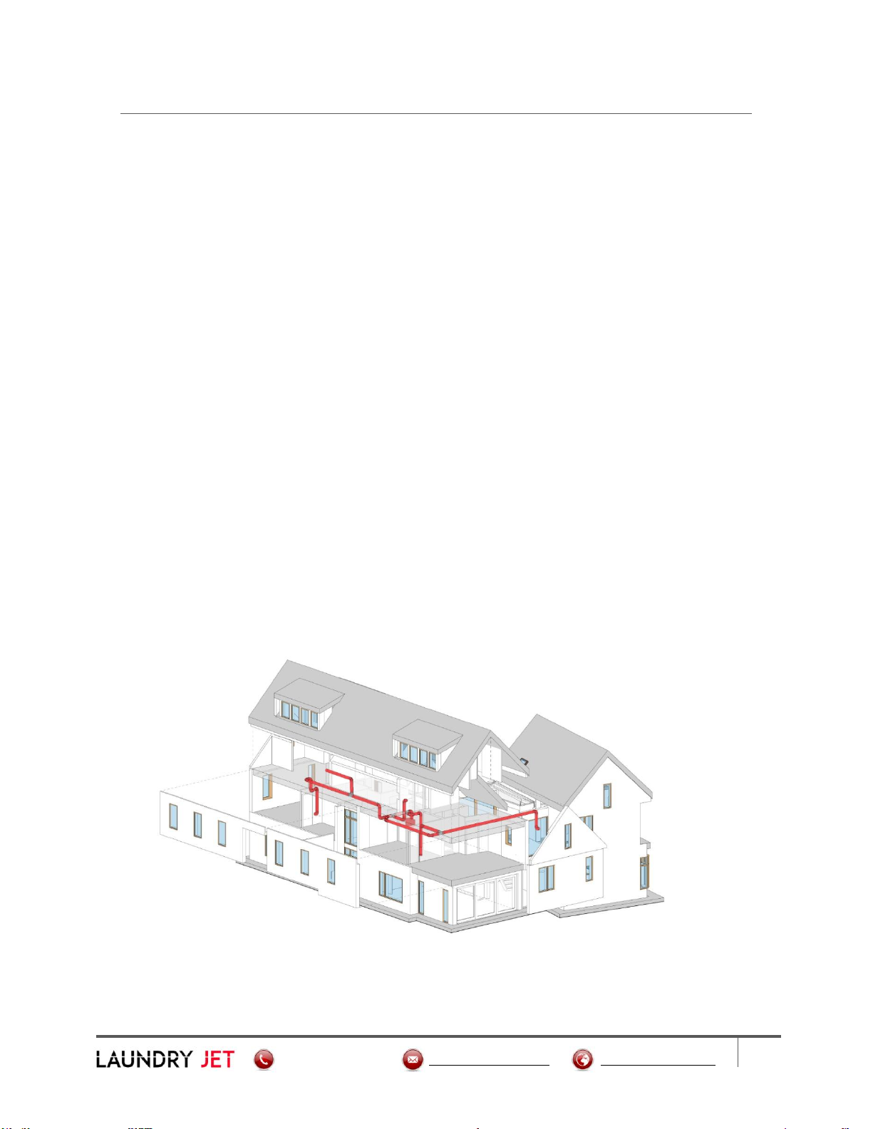
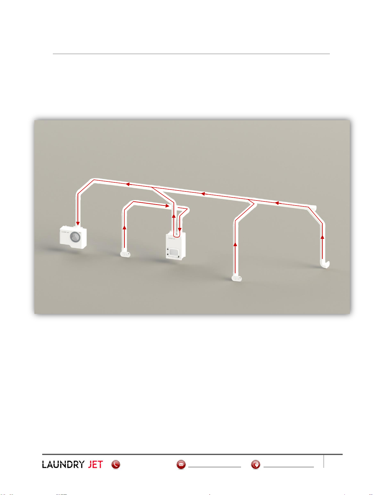
Laundry Jet Return Unit Piping and Airflow
▪The Return Unit has no power, and is used as an "interceptor".
▪It is connected into the pipe network as illustrated above.
▪The top right hand entry of the Return Unit connects via pipe to a dedicated port in the
laundry room.
▪The top left hand entry of the Return Unit connects the suction airflow of the main pipe run.
▪The red arrows in the illustration above show the airflow throughout the system.
7
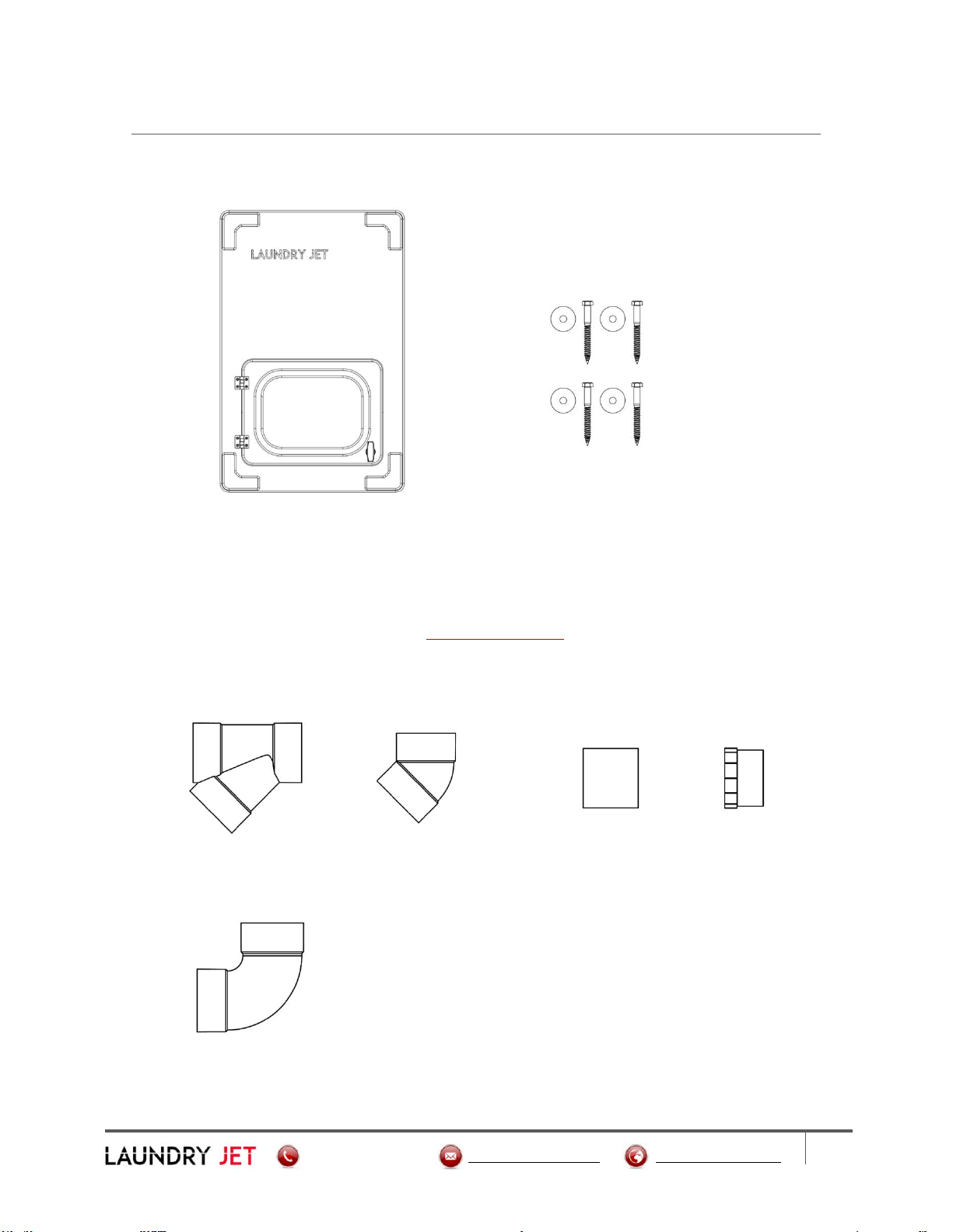
Contents
3Contents
Laundry Jet Return Unit Hardware Kit
Pipe Components
All Fittings are 6" SDR35 White Solvent Weld
6 Inch Wye 6 Inch 45° Elbow 6 Inch Coupler 6 Inch Cleanout
6 Inch Swept 90°
8
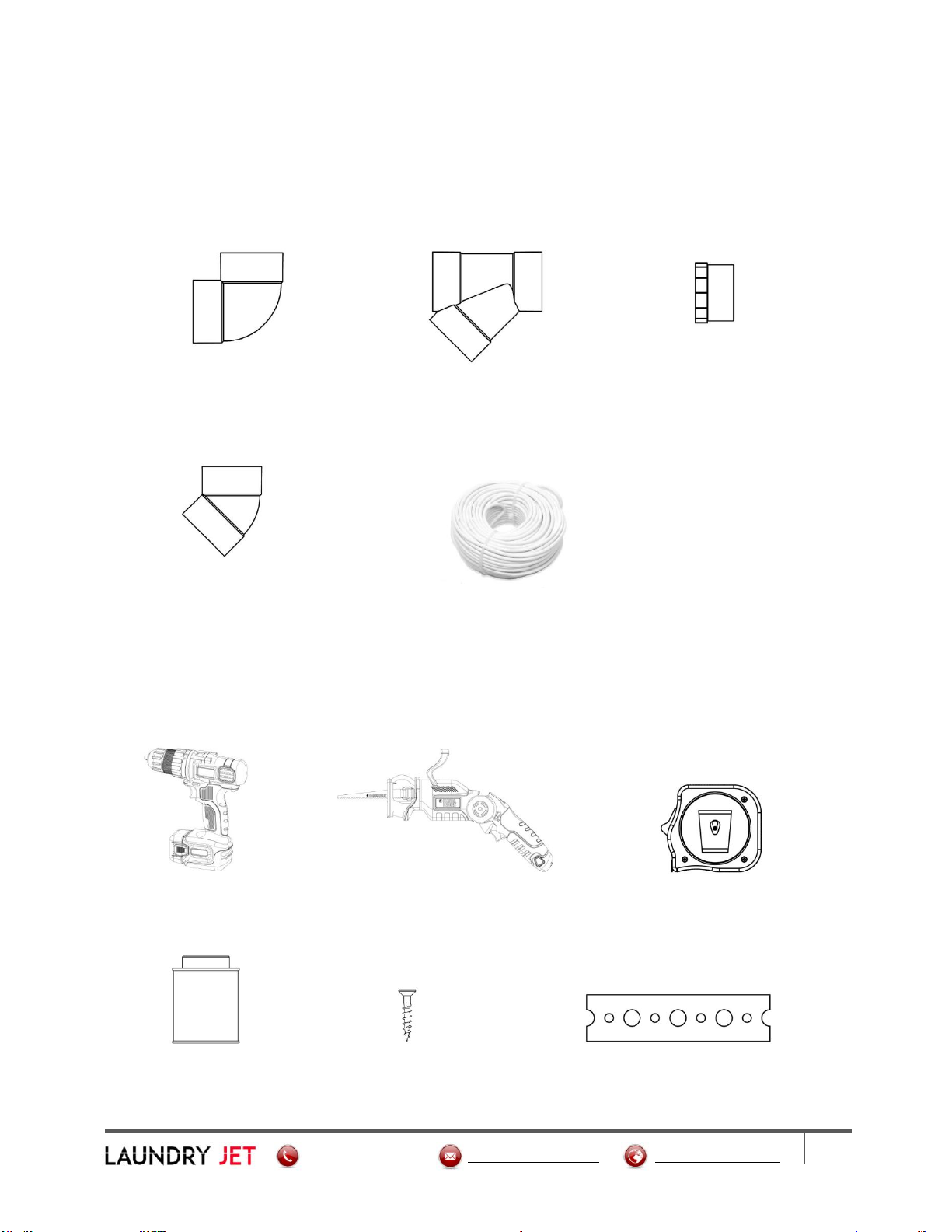
Components & Tools
4Pipe Installation Overview
Components
Port 90 Assembly 6 Inch Wye 6 Inch Cleanout Adapter
6 Inch 45° Elbow Cable Bundle
Tools
Cordless Drill Sawzall Tape Measure
Clear 2 Part PVC Glue 1" Wood Screw Plumber's Metal Strapping Tape

9
Pipe Installation Standards
4.1 Pipe Installation Overview
Pipe Installation Standards
Required Piping Installation Standards
▪All joints must use a minimum entry angle of 45 degrees with a break distance of 18 Inches
(460 MM). See Image below.
▪Pipe cuts must be straight and de burred before seating.
▪Pipe must be completely seated in fitting connections.
▪Seal all joints using standard PVC glue.
Connections must be glued around 360 degrees
to ensure maximum system performance.
▪System must be strapped with “plumbers tape”
(or equivalent) every 6 feet. Port 90 must be
strapped and secured prior to Port installation.
▪Install Cleanout ports every 50 feet on angled runs. Straight trunk lines can run up to 100
feet with cleanouts at either end.

10
Port Drop Installation
4.2 Pipe Installation Overview
Port Drop Installation
▪Mount port 90 using the Port 90 Mount Bracket. See Page 11 for Port 90 Installation. Use a
standard SDR 6" Swept 90 for your Port Drop Installation. Block and strap drop line at
midway point
Table of contents
Other LAUNDRY JET Laundry Appliance manuals


