Lawn Genie 416LG Installation guide

SOLID STATE 6 STATION
LAWN SPRINKLER
CONTROL
G
STAllOFJ
LAWN SPRINKLER CONTt3OL.
INSTALLATION AND
MODEL OPERATING GUIDE
416LG

DESCRIPTION
VAl_VES
_ __
.-
PIIMP
MAtiNE
TIC
s
rAlfrEH
COMMON
CONNECTION
TO
ON; PIIMf’
STAN1
EH
SICK
OF EACH VALVE WIRING
I
60Hz
The
416LG Is a solid slate 6
station
lawn sprinkler control lealuring a dual
program
that
permits watering lawns and shrubs according lo different
schedules. Watering may be programmed lrom every 14 days lo as many as
three limes a day. The watering lirne can be set from
1
minute lo 99
minutes
lor
each circuit.
Slep 1.
Slep 2.
Slep 3.
INSTALLATION INSTRUCTIONS
Select location
for
controller
in
a protecled area near a
110
Volt
duplex receptacle. Longer distances (up to several hundred feet)
between
the
controller and the 110 Volt duplex receptacle are
permissible by replacing the supplied power cord wilh similar
18
gauge cord available at hardware and electrical supply houses.
NOTE: Avoid using a receptacle
that
is on a switched
circuit.
install
one No.
8
screw at eye level at
selected
location. leaving
head
of
screw extended
1/8"
Hang controller on screw by insert-
ing head of screw into keyhole opening on back
of
control
box.
NOTE: Installing on plaster or masonry walls should be done with
plastic
or
lead
shields to
secure
screws.
Open control box,
straighten
into desired position and install Iwo screws through
holes in wiring compartment.
Wiring to the valves can be placed underground alongside the
pipes. Run one common wire to each location lo serve all the
valves at that location. Use 18 gauge solid wire plastic jacketed
thermostat control wire for runs not over 800
feet
and 18 gauge
over 800 feet. Be sure all splices are soldered or joined with wire
nuts and sealed with vinyl cement or other suitable
water-proof-
ing cement. This wire is available from your dealer in
2,3,4,5,6,7
and 8 color coded wires.
IMPORTANT:
The power transformer is
protected by a circuit breaker. Do not connect a valve or combi-
nation
of valves requiring more than 1 AMP. at 24 VAC.
NOTE: DO NOT CONNECT THE PUMP START LEAD DIRECTLY
TO THE COMMON TERMINAL. IF A PUMP STARTER RELAY IS
NOT USED LEAVE THE LEAD DISCONNECTED.
CAUTION: PLACE
III
RAIN
SWIT
CH
IN
THE
RAIN POSITION
BEFORE
CONNEC
T
ING VALVE WIRES TO THE CONTROL. DO
NOT
CONNECT
OR
DISCONNECT
VALVE WIRES FROM AN
ACTIVE
(HOT)
CIRCUIT.

Step 4.
Slep 5.
Slep
6.
Bring
valve
wires up through insulated bushing at right side of
box. Connect the wire from valve
#1
to the terminal on control
chassis marked 1. connect valve
#2
to terminal 2. etc. Connect
the
common wires to
the
terminal on chassis marked Comm.
Connect power leads to “plug-in” transformer. one
lead
lo each
terminal. being certain
that
terminals on cord are not touching.
Remove center screw from cover plate of wall outlet, plug
trans-
former into bottom socket
of
duplex outlet, replace screw
through transformer bracket, thus securing transformer and
cover plate in position.
NOTE: It is
possible
to develop an electrical
transient
when
con-
necting power lo the control. This may cause
the
time
display
to
read other than
d1
400A. To remedy
this
situation
unplug
the
transformer then reinserl
it
into the wall
receptacle.
Connect a 9 volt alkaline transistor
battery
(not
supplied) to
the
battery connector and place in the wiring compartment. NOTE:
Use a Mallory MN1604, Eveready 522 or equivalent battery.
CAUTION: DO NOT ALLOW THE BATTERY
CONNECTOR
TO
CONTACT THE CONTROLLER’S TERMINAL STRIP.
TO REMOVE CONTROL CHASSIS: Remove screws
(1)
that
retain
con-
troller
chassis (2) in
control box.
NOTE: Due to varying
regulations,
check your local
codes.
l
PROGRAMMING INSTRUCTIONS
The sequence for programming the
416LG
solid state control
are
as
follows:
1.
Read the programming instructions.
2.
Fill out the program card.
3.
Program the control.
NOTE: PRESS KEYS WITH FlNGERS ONLY
Step
1.
SET DAY AND TIME
_-__-
SEVEN DAY NUMBER CHART
DISPLAY EXAMPLE
~-CAMorPM
TIME OF DAY
DAY
Upon power-up the display will automatically show a day number (1
means Sunday) and time of 4:00 P.M. You are to set the clock to the
present day and time. Change the day number by repeatedly pressing
the
IfiZXi)
key until
It selected day number appears on the display. Set the
time by pressing the required numbered keys and
[AMlPMJ
,
if needed.
NOTE: Noon is 12:OO P.M. and midnight is 12:00 A.M.
-_-_
A. Press [CLOCK] The clock is now stopped and ready lo
--
be changed.
B.
Press
(NEXil
repeatedly, to change the day number.
C.
Press
!I
0
Cl
0
three or four numbered keys for time
of
day.
--
D. Press
PM/PM]
lo change the displayed A or P.
E. Press
m
The
clock
starts.
NOTE: If you press a wrong key press
jCLEAR1
then set the time
again.
If
you may have set an invalid time, such as 1300, upon
pressing
lm
the display will go blank except for an
"E,"
indi-
cating an error.
PresspGfl
and repeat Steps C and E above.

Step
2:
Step
3:
PROGRAM WATERING CYCLE START TIMES
DISPLAY EXAMPLE
Cl
201111
CYCLE
--IT
-L
AM
or
PM
START TIME
Upon power-up cycle No. 1 will preset
with
a time of 2:00 A.M. You can
enter
into
memory up to three
start
times using the
lm]
key to change
cycle numbers and numbered keys to program the start times. Start times
programmed will repeat once every 24 hours. At each cycle
start
time
Stations
1 through 6, programmed to water in Step 3, will water sequen-
tially.
NOTE: There must be a minimum of one minute between the end of
the
last
station's
watering and the next start time. lf an overlap does occur
the next start
time will
be bypassed.
EXAMPLE: Cycle start time C1: 200A
Watering time 10
minutes/station
For 6 stations
:
60 minutes.
Next possible Cycle
start
time C2: 301A
A.
B.
C.
D.
E.
F.
G.
H.
I.
Press
Cycle
No.
1 is
now
displayed
Press
:.‘i
Cl
0
0
three or four numbered keys for
time
of day.
Press 1to change the displayed A or P.
Press (ENrERj
.
Cycle No. 1 is now entered
into
memory.
Press
[NEXT]
to display Cycle No. 2.
Repeat Steps B, C and D for the second start time.
Press
(-1
to display Cycle No. 3.
Repeat Steps B, C and D for the
third
start time.
Press
m
lo
return
the
display back to
the
clock.
IF
ONLY ONE START TIME IS DESIRED. PERFORM
STEPS A,
B,
C,
D
AND
I
ONLY.
NOTE:
If
you press a wrong key press
mj
then re-enter
the correct time. If you should program an invalid time, NOTE: If you press a wrong key press
(CLEARI
then
re-enter
the
such as
13:00,
upon pressing
1-1
the display will go correct program number and watering run time. If you should
blank except for an
"E",
indicating
an error. Press program an invalid program number, such as 3, upon pressing
1-1
and
repeat Steps
B
and
D. IENTER]
the display
will
go blank except for an
"E"
indicating
an error. Press clear and repeat Steps
B,
C and
D.
PROGRAM STATION PROGRAM NUMBERS
AND WATERING RUN TIME
___
_._
-
_.._-
-.-_-_-.
__
__.
___
STATION WATERING
PAOGRAY
CHART
_..
..-
_
--
---.-.
.
.._-__._.._
__..
KEY NO. PROGRAM
_
_
_.-
--_.
. . _
0
NO
WATIRINO
;
PAOGRAM
I
,L.rn,
;
_
..
_
PROGAAM
I
(Shwb,)
DISPLAV
EXAMPLE
The
Dual Program capability of the
control
can be achieved as follows:
Divide the valve stations to satisfy your watering needs. Example: Sta-
tions 1 through 4 Program 1
(lawn),
and
Stations
5 and 6 Program 2
(shrubs). These groups of stations may be
watered
independenlty of
each other or
together
by using an appropriate program number in Step 4.
.
Upon power-up all six stations will be preset with Program 1 and a 5
minute watering run time. You are to enter a program number and a
watering
run time for each
station.
The first numbered key pressed will be
the program number while the
next
one or
two
numbered keys pressed
will be the run time in
minutes.
(1
to 99 minutes.) NOTE: No
matter
what
the watering run time
a
"0"
program
number will prevent watering.
A "0"
only, can not be
entered
for a
watering
run time.
A.
B.
C.
D.
E.
F.
G.
H.
I.
Press
Station
No. 1 is now displayed.
Press
LI
one numbered key for the selected program
number
Press i:I
Cl
one
or
two numbered keys for the desired
watering
run
time for Station No.
1.
Press
1-1
Station No. 1 is now entered
into
memory.
Press
mm]
Station
No. 2 is now displayed
Repeat Steps
B,
C and D for Station No. 2
Press
I-r]
for Station No. 3
Repeat Steps B, C, D and E for a
total
of six stations.
Press
m
to return the display back to the clock.

Step 4: ANY PROGRAM CAN BE REVIEWED AS FOLLOWS:
Press
Press
E]
repeatedly to display programs.
Press
m
to
return
to
the
clock
PROGRAM DAY WATERING PROGRAM NUMBERS
DAY WATERING PROGRAM
CHART
KEY NO. PROGRAM
--
0
NO WATERING
~--.-
__.._
1
PROGRAM 1 (Lawn)
--
2
PROGRAM 2 (Shrub,)
‘--
3
PROGRAM 1 AND 2 (Both)
._..
,
---
Idl
Pi
T.
DAY.
Program
Upon power-up all
fourteen
days will be preset with Program 1 (Lawn).
You are to enter a program number, which corresponds to the group of
stations you wish to water on that day, for each of the
fourteen
days by
pressing
a nurnbered key.
A.
B.
C.
D.
E.
F.
G.
H.
DAY
Press
SIII
PROGM
.
Day No. 1 is now displayed.
Press
number.
III
one numbered key for the selected program
Press
[-6%-l
Day No. 1 is now entered into memory.
Press
[aq
Day No. 2 is now displayed.
Repeat Steps B and C for Day No. 2.
Press
)NEirTl
Day No. 3 is now displayed.
Repeat Steps
B,
C and D for a
total
of fourteen days.
Press
m
to
return
the display back to the clock.
USE OF THE PROGRAM CARD:
.
The
program
card
can
be
an
aid
tO programming and a record for
future
use. This could be
useful
in the
event
of a power outage and a
battery
failure. The controller would power-up wilh a preset program and
your
program card would be your only record of your programming. The
program
card has boxes which are to be filled In with the numbers you
want programmed. Read the programming
instructions
before marking
the card.
1.
When you
enter
the
card data
into
the controller’s mernory
mark the card with the day number and time.
2.
Determine the
start
times you wish in a day and mark the card
with these times.
3.
Determine what program number you want for each of the six
stations and mark the card. Mark a
"0"
for any station not to
water or any station
without
valve wires.
4.
Determine the
watering
run time for each of the six stations
and mark the card.
5.
Determine the day program number for each of
fourteen
days
and mark the card.
Following the program
instructions
enter the above data into the con-
troller’s memory.
NOTE: If you press a wrong key press
L-1
then re-enler the
correct program number. If you should program an invalid
program number, such as 4. upon pressing
IENTEFJ
the
display will go blank
except
for an
"E"
indicating an
error
Press
(CLEAR] and repeat Steps
B
and C above.

1.
2.
3.
4.
5.
OPERATING INSTRUCTIONS:
,
DISPLAY: The day number and time of day will be displayed except
when a watering cycle Is In progress or while programming. When on
battery operation the display will be blank.
KEY BOARD: Use to program the controller’s memory, recall lor view-
ing data stored in
the
memory, and to
start
a manual operation.
NOTE: PRESS KEYS WITH FINGERS ONLY.
RAIN SWITCH: For programmed watering, move
switch
to
the
auto
position. For shutdown
of
system (rain) rnove
switch
to the rain
position.
CAUTION: If a watering cycle
is
indicated In progress press the
[-_rZiZkey
before moving the rain swllch,
otherwise
the
memory
may be
lost.
CIRCUIT BREAKER: A tripped circuit breaker
indicates
an
electrical
problem
in
the wiring to the valves or
in
the valve. To reset the circuit
breaker, push
the
reset button.
NOTE: An Electronic
Short
Protection circuit prevents an external
short circuit from damaging the solid
state
components. If, during a
watering cycle, a
station
detects a short circuit
the
control will imme-
diately go into a clear mode and return
the
display lo
the
clock. The
circuit breaker may or may
not
trip.
BATTERY,-MEMORY BACK-UP: In the
event
of a power outage
the
battery will maintain the programmed memory and a reasonably
accurate time
of
day for a
continous
period
of
48 to 72 hours.
If
there
are only brief power outages the battery should last for a year and
should be replaced annually. Replace only wilh a 9 volt alkaline
battery, such as Mallory MN1604 or Eveready 522.
NOTE: Without battery back-up (no battery or dead battery)
the
control will revert to the preset conditions mentioned
in
Sleps 1
through 4 upon power-up. The control will function as follows:
ten
hours, after return of power, Stations 1 through 6 will waler
sequen-
tially for 5 minutes per station. The control will repeal this cycle once
every 24 hours thereafter until reprogrammed.
MANUAL OPERATION:
MANUAL MODE 1: All stations programmed lo
water
on
the
displayed
day will water
consecutively.
Press MAN
then
m.
MANUAL MODE 2: One selected station will water
for
its programmed
watering run time. Press
1-1
,
[m]
repeatedly,
until the
selected
station
number
appears
on
the
display, then
a
.
MANUAL MODE 3: One
selected
station will waler
for
an
extended
.___
watering run time.
(maximum
of 99
minutes.)
Press
&fir!)
,
lrJExfl
,
repeatedly, to
select
the
station number,
0
i3
one
or two numbered
keys for the new manual
watering run
time.
then
[
G-1 (The auto-
matic run time will
not
be changed
by
this
operation.)
NOTE: A Station
with
a
"0"
program
number
can
not
be
manually
watered.
Use
the
f-R]
key to stop
any
mode of watering
before
its time to
stop. The display will
return
to
the
clock.
L
a

LIMIT
ED
WARRAN
TY
NO IMPLIED
WARRANTIES (INCLUDING
BUT NOT
LIMITED
TO
FITNESS FOR A PARTICULAR PURPOSE, WHERE AP-
PLICABLE, AND MERCHANTABILITY) SHALL
EXTEND
BEYOND THE PERIOD OF
THE
EXPRESS WARRANTY
DESCRIBED ABOVE. IN NO EVENT SHALL
RICHDEL
BE
RESPONSIBLE FOR INCIDENTAL OR CONSEQUENTIAL
DAMAGES TO PROPERTY
WHICH
MAY ARISE FROM OR
RELATE TO
THE
PURCHASE OF ANY
RICHDEL
PRODUCT.
Some states do not allow limitations on how long an implied
warranty lasts or the exclusion or limitation of incidental or
consequential darnages, so one or both of the above limitations
may not apply to you.
This warranty gives you specific legal rights, and
your
may
have other rights which vary from state to state.
To exercise your warranty, send unit, with photocopy of dated
receipt, postage prepaid
to’:
1
1
Table of contents
Popular Network Router manuals by other brands

Planet Networking & Communication
Planet Networking & Communication VC-200M user manual

ZyXEL Communications
ZyXEL Communications PRESTIGE 334 Specifications

Draytek
Draytek Vigor 2800VG Declaration of conformity

peplink
peplink Pepwave MAX Series user manual
B&B
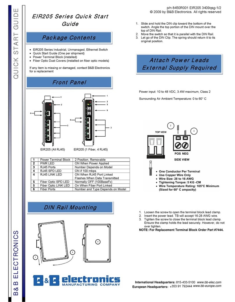
B&B EIR205 Series quick start guide

Cisco
Cisco 2650 - 2650 Router Hardware installation guide
