LAZY MAISONS LM-BZS2 User manual

Please Read Instructions Before Use
ASSEMBLY INSTRUCTIONS
LAZY MAISONS HEIGHT ADJUSTABLE TABLE
STRAIGHT 2 STAGE T LEG BASE
Model Number : LM-BZS2

2
12
1.Read instructions carefully.
Check that no parts are
missing.
Single Sided
Wrench
Socket Head
Wrench Electric Drill
do not assume any responsibility for product that is altered in any way.
2.Carefully identify each
component, especially those
that are similar. The most
common mistake is mixing up
the order and placement of
parts.
WARNING: Failure to follow the assembly instructions in this manual can result in product
damage, or personal injury.
IMPORTANT::KHQSODFLQJWDEOHLQ²QDOORFDWLRQEHVXUHWKHUHLVDPSOHURRPIRUDGMXVWPHQW
around ALL sides, and at the highest (4”) and lowest (28”) points the table can reach. Make
VXUH WDEOH ZLOO QRW FRPH LQWR FRQWDFW ZLWK DQ\ ²[HG REMHFWV ²[HG WRSV VWRUDJH VKHOYLQJ
HWF
while adjusting.
7KDQN\RXIRUFKRRVLQJ:HDSSUHFLDWHWKHWUXVWDQGFRQ²GHQFH
\RXKDYHSODFHGLQXVDQGDUHFRPPLWWHGWRSURYLGLQJ\RXWKHEHVW
possible product.
1. As with all power-operated products, please follow instructions closely and handle with
care.
2. When moving tables, please lift the tables, do not drag or tilt the table on one leg as
misalignment may occur.
3. Check that the load on the table does not exceed limits (120kg
maximum
on
straight).
6.
%HIRUH
²UVW
XVH
SHUIRUP
UHVHW
RSHUDWLRQ
7.
If,
after
trouble
shooting
the
problem
persists,
contact
Customer
Service
for
further
assistance.
Tools Needed
Introduction
RIIHU DFRPSUHKHQVLYH OLQHRIRI²FH IXUQLWXUH IRUHYHU\ VSDFH DQGUHTXLUHPHQW QRZ
including My-Hite, a height adjustable table that allows for standing or sitting while working.
User Notes
4. The
input
voltage
should
be
within
100-240V.
5. Use
the
glides
to
properly
level
the
table
before
use.Table
should
be
level
and
aligned
at
all
times.

Parts List
Column Leg
A (2 pcs)
Crossbeam
D (2 pcs)
Control Box
J (1 pc)
Pressure Retainer
Lever
M (2 pcs)
Pin
N
(2
pcs )
R-Wire
Clip
O
(10
pcs)
Control Wires
S (2 pcs)
Power Cord
T (1 pc)
Wire Clip
Q (4 pcs)
Connecting Beam
E (2 pcs)
Wood Screw
M4.8×19
I (14 pcs)
Metal Screw
M10×16
F (8 pcs)
Longitudinal Beam
G (2 pcs)
Feet
B (2 pcs)
Socket button head bolt
M6×35
C (8 pcs)
Rubber
Washer
H
(12
pcs)
Wood Screw
M3.5×15
L (2 pcs)
Wood Screw
M3.5×16
P (10 pcs)
Hex Wrench
R (1 pc)
Display
K (1 pc)

Installation Steps
Step 1
3ODFHZRUNVXUIDFH²QLVKHGVLGHGRZQRQDEODQNHW
Step 2
G
longitudinal
beams
into
crossbeams
assembly
and
slide
to
lock
into
place.
Repeat
on
other
side.
Step
3
Stretch
D
crossbeams
to
where
you
think
it
is
,then
use
I
(12)
wood
screws,4.8
mm
through H Rubber W
saher
to
secure
G Longitudinal
Beams and
D
crossbeams
to
worksurface
as
shown.Repeat on other side.
.
Use
(8)
metal
screws
,M1016
mm
to
secure
connecting
beams
as
shown.
.
H
Rubber Washer
G
Longitudinal Beam
D
Crossbeam
G
Longitudinal Beam
D
Crossbeam E
Connecting Beam
H
Rubber Washer
Q
Wire Clip
I
Wood Screw
F
Metal Screw
Worksurface

Step
Step
2
M
4
&
.5
-N
M4
&
.5
(($$%##$%&
$5
$-
6$%"
&-
"
Pressure
Retainer
Lever
4
M
N
A
Column Leg
D
Crossbeam

Step7
Secure J Control Box in the desired location with I (2) Wood Screw,M4.8×19.
Step8
Secure K Display in the desired location with L (2) Wood Screw,M3.5×15 with washers.
Step9
Use Q Wood Screw,M3.5×16 and O Sticky Card,or Q(4)Wire Clips to secure wires below the worksurface
as shown.
Step10
Attach B feet to A column leg with C (8) socket button head bolts, M65. Tighten bolts securely.Repeat
on other side.
C
Socket Button Head Bolt
B
Feet
A
Column Leg
Q
Wire Clip
J
Control Box
T
Power Cord
L
Wood Screw
K
Display O
Sticky Card
P
Wood Screw
S
Control Wires
I
Wood Screw
6

6FKHPDWLFYLHZRI ZLULQJ Step 1
Turn table
right side up, adjust the glides as necessary, and plug the power cord into a100-240v
outlet.Make sure the length of the plug-in cord is appropriate to both reach the outlet, AND for
the
distance
the
table
will
travel
up
and
down.
It is important to perform the reset procedure stated below
EHIRUHXVLQJ\RXUWDEOHIRUWKH²UVWWLPH
Range:
2$$
at
lowest
to
45''
highest.
!"#$%&
1. Press and hold ޔ & ޕsimultaneously for more than 3 seconds till legs begin to move
down at half speed of normal operation.
2. Keep pressing buttons till legs move down to the lowest position and rebound 2-5 mm,
then stop.
3. Release together. Reset is completed
%
(a) The reset procedure must be completed after table is installed or parts replaced.
(b) If reset process is interrupted, the system will stop running and will need to be reset to
operate again.
T
Power
C
A
Column eg
J
S
Control Wires
S
Control Wires
A
Column eg
K
Display

"After reset, memory settings need to be set again.
2) Set Memory Position
5HPRYLQJ3UHVHWV
6HW0D[LPXP+HLJKW
5) Set Minimum Height
7) Display in Inches or Centimeters
&OHDU0LQLPXP0D[LPXP+HLJKW
1.
Use ޔ& ޕbuttons to adjust the table.
2.
Press S, then press button 1 or 2 or 3 or 4 within next 3 seconds to set height for that #.
Display position 1,2,3,4 is saved.
1.
3UHVVDQGKROGEXWWRQ6PRUHWKDQVHFRQGV'LVSOD\ZLOO³DVK©¨¨¨ª
2.
5HOHDVHEXWWRQ63UHVVEXWWRQZLWKLQVHFRQGV7KHVFUHHQGLVSOD\V©+ªZKLFK
LQGLFDWHVWKDWWKHSUHVHWVDUHRII©+ªLQGLFDWHVSUHVHWVDUHRQ
3.
Press ޔ
or ޕ
to change the current function of turn on or off.
©+ªH[SUHVVIXQFWLRQLVRII©+ªH[SUHVVIXQFWLRQLVRQ
4.
Touch and hold button S for 2 seconds. Preset is on or off.
1.
Press and hold S. Without releasing button S, press and hold 2 for 3 seconds.
2.
&RGH©&ªZLOOFOHDU
Press and hold S. Without releasing button S, press and hold ޕfor 3 seconds.Release both
buttons. The height information will toggle between inches and centimeters.
1.
Use ޔ& ޕbuttons adjust table to desired maximum height.
2.
3UHVVDQGKROG6WKHQSUHVVDQGKROGIRUDERXWVHFRQGV5HOHDVH/HWWHU©Ì/̪IODVKHV
on the screen. This means the table will not go above this height.
©B/BªIODVKHVRQWKHVFUHHQ7KLVPHDQVWKHWDEOHZLOOQRWJREHORZWKLVKHLJKW
1. Use ޔ& ޕbuttons to adjust table to desired minimum height.
2. Press and hold S, then press and hold 1 for about 3 seconds. Release both buttons. Letter

roubleshooting 2 stage
Error Code
Explanation
Cause Solution
E01
Connection ssue
he leg is disconnected rom the control box.
Check the cable connections between leg and computer. Reset
display.
If problem persists
contact % )ustomer ervice.
E02 Continous peration Continous operation or 5 min. Let motor rest or 10 min. hen try again.
Ifproblempersists
contact /ustomer ervice.
E03 abletop verload
he tabletop load exceeds the weight limit.
Check that weight on table does not exceed weight limit.
2 stage straight -120kg
If
problem
persists
contact
/
ustomer ervice.
E04 Control Box Malunction Control Box Malunction Perorm reset operation.
Ifproblempersists
contact /ustomer ervice.
E05 Display is roen Display locked or 30 seconds. Perorm reset operation.
Ifproblempersists
contact /ustomer ervice.
E06 Communication
Disconnected Connection lost between display and control box. Check cables. Perorm reset operation.
Ifproblempersists
contact /ustomer ervice.
E0 Display shows less than 0 he height on display is lower than 0.
Perorm reset operation.Set display height to 28 .
Ifproblempersists
contact /ustomer ervice.
E08
Motor Short Circuit
Motor cable damaged Check the motor cable or damage.
Ifproblempersists
contact /ustomer ervice.
E09 Hall Error Hall count error Perorm reset operation.
Ifproblempersists
contact /ustomer ervice.
E10
Actuator Error Failure o control box actuator
Disconnect power supply or
1
minute then plug in.
Ifproblempersists
contact /ustomer ervice.
E11 Rebound Malunction Rebound unction error Perorm reset operation.
Ifproblempersists
contact /ustomer ervice.
E12 yroscope abnormal
1. he gyroscope sensitivity sensor module is abnormal
2. ilt the table
1.Restart the power.
2.Lay the desktop lat or place the control box lat.
If
problem persists contact /ustomer ervice.
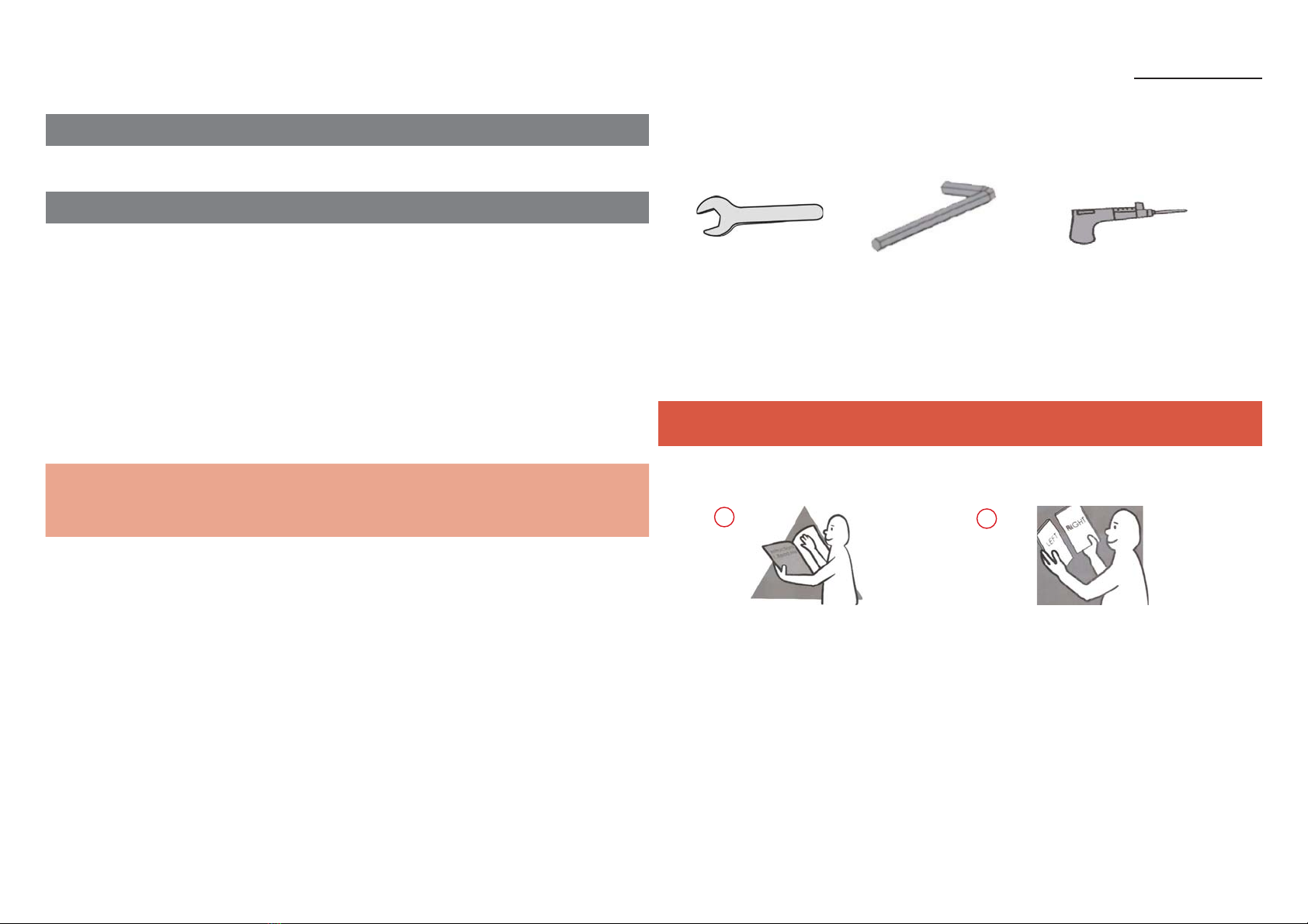
GENERAL TIPS
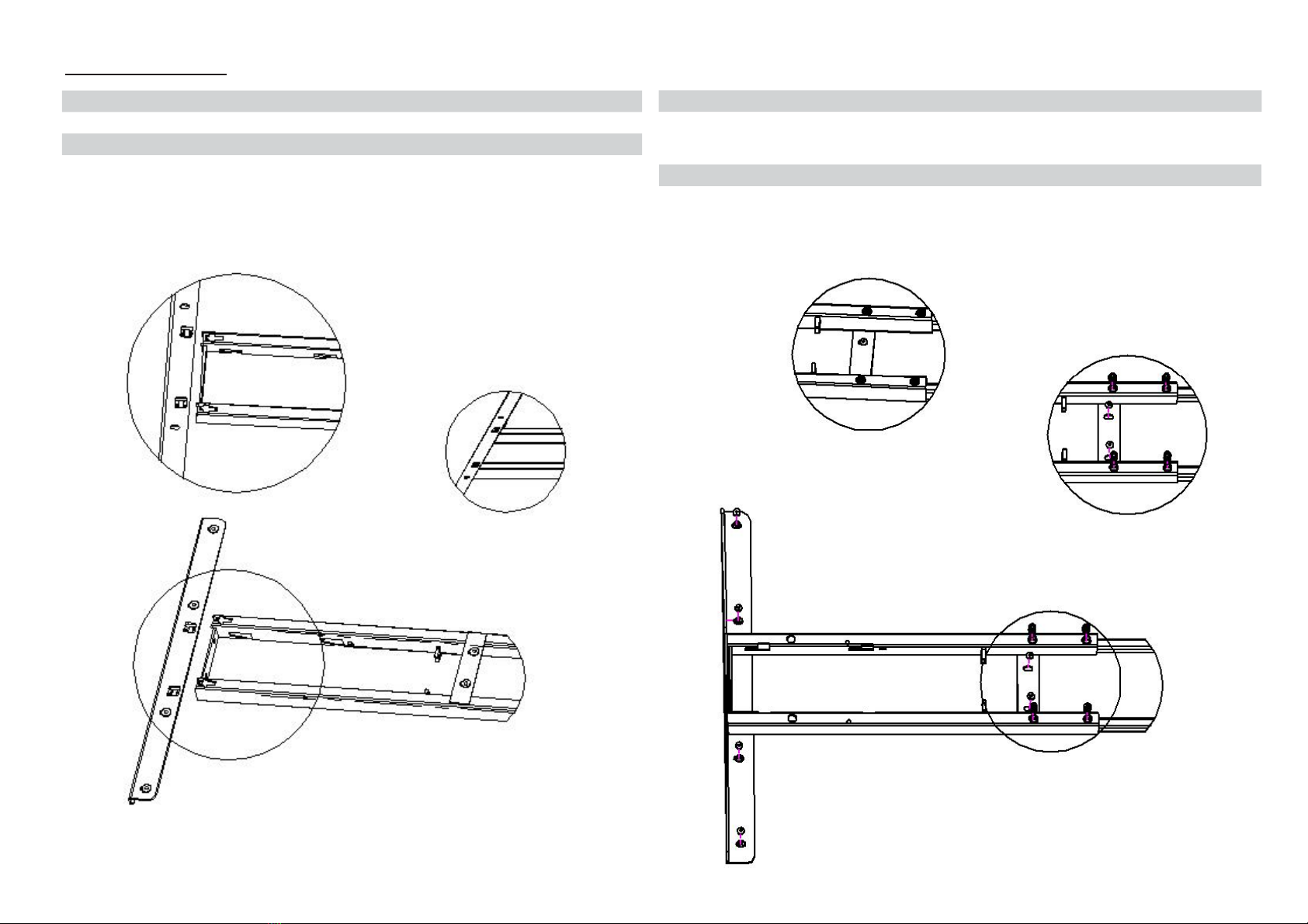
Follow assembly instructions closely
Do not overload the tables (120kg maximum straight)
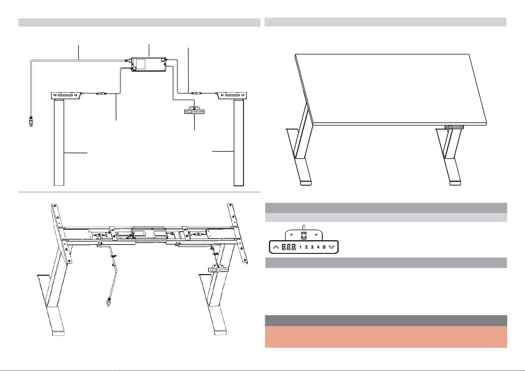
he input voltage should be within100-240
se the glides to properly level the table beore use
When moving the table do not tilt the table on one leg or misalignment may occur
Beore irst use perorm reset operation
ater trouble shooting the problem persists contact Customer Service or urther
assistance
0
Table of contents
Other LAZY MAISONS Indoor Furnishing manuals
Popular Indoor Furnishing manuals by other brands

Kinnarps
Kinnarps WORKS DS Assembly instructions

Cooper Lighting
Cooper Lighting PD7 specification

FURNITUREBOX
FURNITUREBOX CALLA Assembly guide

VISIONARY DESIGNS
VISIONARY DESIGNS VK-1334 Setup instructions

Hailey Home
Hailey Home CT1682 Assembly instructions

Furniture of America
Furniture of America CM6495 Assembly instructions