lbx INC-C User manual

INC-C CO2Incubator
Please read the User Manual carefully before use, and follow all operating and safety instructions!
user manual
english

2
User Manual
INC-C CO2Incubator
Preface
Thank you for purchasing our product. Users should read this manual carefully, follow the instructions and
procedures, and be aware of all preventive measures when using this instrument.
Service
If help is needed, you can always contact your dealer or Labbox via www.labbox.com.
Please provide the customer service representative with the following information:
▪Serial number
▪Description of the problem
▪Your contact information
Warranty
This instrument is guaranteed to be free from defects in materials and workmanship under normal use and
service for a period of 24 months from the date of invoice. The warranty is extended only to the original
purchaser and shall not apply to any product or parts that have been damaged due to improper installation,
improper connections, misuse, accidents, or abnormal conditions of operation.
For claims under the warranty, please contact your supplier.

3
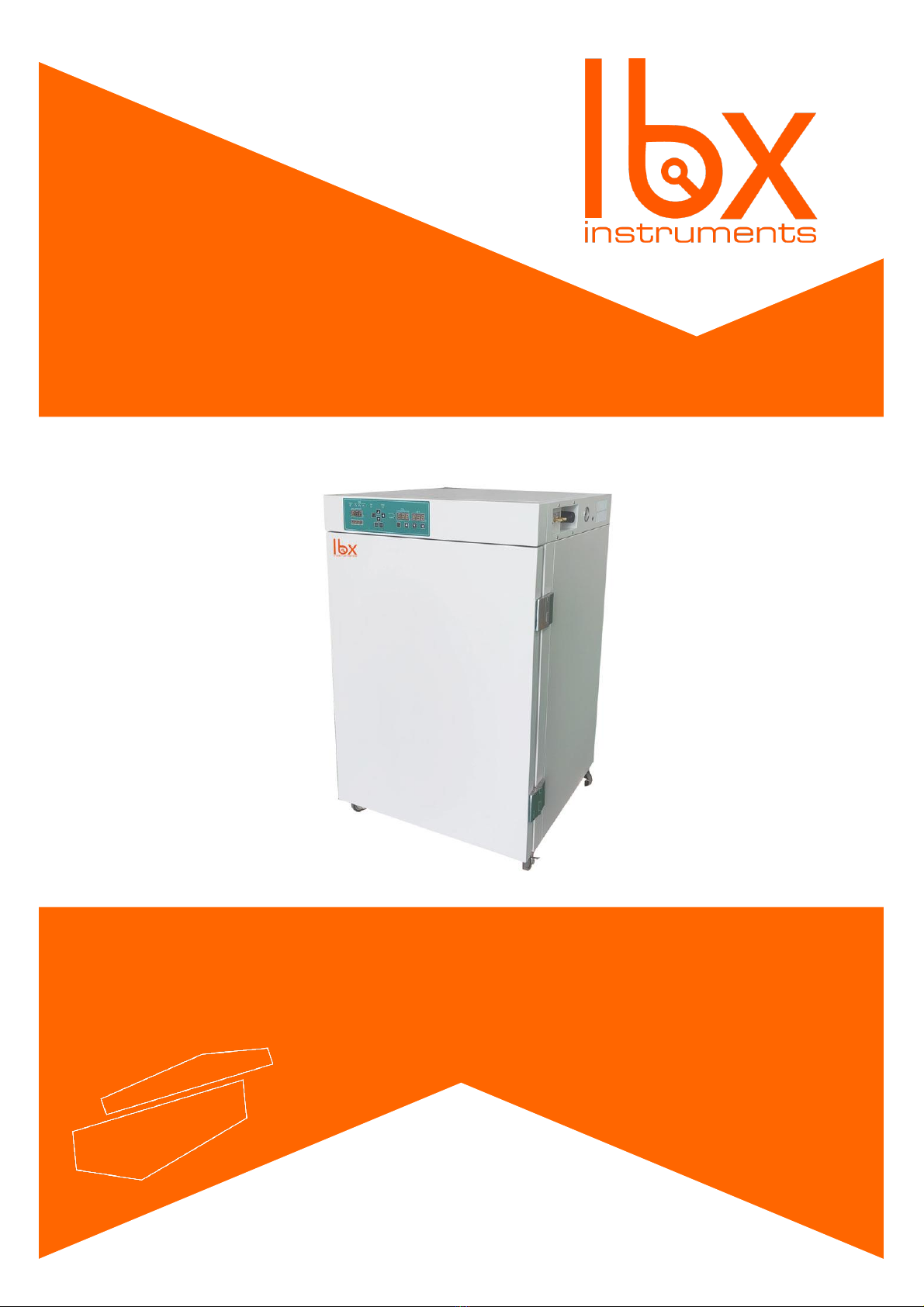
1. Application Range:
The INC-C CO2Incubator is suitable for use in modern medicine, biochemistry, agricultural science research, and
industrial production departments, for the cultivation of biological cells, tissues, and bacterial cultures.
2. Features:
1. This product is made of high-quality thermal insulation materials and adopts a water jacket structure,
with an air duct liner and fan forced convection that ensures uniform box temperature and equilibrium
CO2 concentration.
2. It uses first-class imported CO2 sensors that detect infrared waves and have gold-plated probes,
ensuring measurement accuracy and a sensor life of up to 15 years.
3. The indoor CO2 concentration can range from 0 to 20%, and a gas filter is used to improve
measurement accuracy and room cleanliness and to reduce the effect of impurities on CO2 gas
concentration.
4. The fans and CO2 valve automatically turn off when the door is open, and heating stops, reducing CO2
gas consumption, and preventing air pollution caused by the entry of impurities.
5. The temperature and CO2 concentration are controlled by intelligent PID control and computer data
analysis, ensuring high precision and strong anti-interference. The temperature control uses two probes to
control the temperature inside and outside the door, ensuring high precision and minimal fluctuations.
6. The adjustment switch is light and flexible to operate.
7. The independent temperature control door reduces the external temperature and prevents frost on the
system of the studio and glass doors.
8. The natural evaporation humidifier maintains good indoor humidity.
9. The box temperature, CO2 concentration, and set parameters are displayed digitally, and the LED
instruction indicates door heat, CO2 entering the air, high-water level, and water shortage.
10. The equipment is equipped with protection features such as super warm and breathe, ensuring safe
operation.
3. Specifications:
•Temperature Control Range (ºC): RT+5~60
•Timing Range: 1~9999 min or no time
•Electric Power: AC220V 50Hz
•Temperature Fluctuation (ºC): ≤±0.2
•Temperature Uniformity (ºC): ≤±0.3
•CO2 Concentration Control Range (%): 0~20
•CO2 Accuracy (%): ≤±0.1
•Time to reach the set CO2 value: <10 min (5 % concentration)
•CO2 Measurement Precision (%): ±0.1

4
Other technical parameters can be seen in the following table:
4. Installation:
1. The equipment should be placed in a dry, flat area that is free from toxic and hazardous gases. It should
be kept away from direct sunlight and have enough space around it for easy maintenance.
2. To use this equipment, you must equip it with 99.9% high purity gas cylinders and a CO2 valve (users
must provide these components themselves). The cylinders should be placed near the incubator and
connected to the “CO2 into the air intake”with silicone hoses.
3. The incubator works best at an ambient temperature of 20 ~ 25 ºC. Set the minimum temperature of the
incubator to at least 5 ºC higher than the ambient temperature.
4. The incubator must be plugged into a reliable grounding power outlet and matched with the
correct plug.
Model
INCC-080-001
Volume (L)
80
Power (W)
600
Studio Size (cm3)
41 x 51 x 40.3
Dimensions (cm3)
57 x 88.5 x 59.5
N.W/G.W (kg)
60/90

5
5. Operating Instructions of the Temperature Controller:
1. Panel Diagram (Equipped Instruments, CO2Temperature Controller)
2. On the right of the panel is a set of keys, the functions are following:
1.
超温
电源 高水位 缺水
门加热
照明
灭菌
气泵1 气泵2
℃
min
水加热 气泵2气泵1 灭菌 照明
Key: This key is a function key, after powered on, press this button to enter the temperature
setting state. Press this button for five seconds to enter the other parameters setting state. When the
instrument is in the set state, the bottom LED will flash.
2. “Air pump 1”Key: Click the button to connect pump 1, press it again to disconnect pump 1.
3. “Air pump 2”Key: Click the button to connect pump 2, press it again to disconnect pump 2.
4. “Sterilization”Key: Click this button, and the indoor sterilization lights will turn on. Click it again, and
the sterilization lights will turn off.
5. “Lighting”Key: Click this button to turn on the lights and click it again to turn off the lights.
6. ▲Key: This key is the addend key. When setting parameters, press the button to increase the value
by 1.
7. ▼Key: This key is the subtraction key. When setting parameters, press the button to decrease the
value by 1.
8. ◄Key: This key is the left key. When setting parameters, press the key to move to the data bit that
needs to be set. In the boot state, click the button to view the indoor temperature.
Note: Please press the key
超温
电源 高水位 缺水
门加热
照明
灭菌
气泵1 气泵2
℃
min
水加热 气泵2气泵1 灭菌 照明
after setting parameters, otherwise the parameters cannot be written to
memory.

6
3. Instructions:
1. When running, the temperature window (top row) displays the inside temperature. The time window
(bottom row) displays the remaining time. When the time is set to zero, the time window displays the
set temperature. When the remaining time reaches 0, it displays “end”and stops running. To rerun it,
press the
超温
电源 高水位 缺水
门加热
照明
灭菌
气泵1 气泵2
℃
min
水加热 气泵2气泵1 灭菌 照明
key.
2. To set the inside temperature and run time, follow these steps: ①Press the
超温
电源 高水位 缺水
门加热
照明
灭菌
气泵1 气泵2
℃
min
水加热 气泵2气泵1 灭菌 照明
key, and the top
row of the digital display will show the temperature settings, while the end-term blinks. →②Use
the ▼, ▲and ◄keys to modify the status. →③Press the
超温
电源 高水位 缺水
门加热
照明
灭菌
气泵1 气泵2
℃
min
水加热 气泵2气泵1 灭菌 照明
key to display the set time on the
bottom row of the digital display. →④Use the ▼, ▲, and ◄keys to modify the time status. →
⑤Once you've set the parameters, use the
超温
电源 高水位 缺水
门加热
照明
灭菌
气泵1 气泵2
℃
min
水加热 气泵2气泵1 灭菌 照明
key to write them into memory, exit the setting
state, and return to running.
3. Set other parameters as follows: ①Press the
超温
电源 高水位 缺水
门加热
照明
灭菌
气泵1 气泵2
℃
min
水加热 气泵2气泵1 灭菌 照明
key for about 5 minutes to enter the other
parameter setting state. The top row of the digital display will show each parameter symbol, and
the bottom row will show the parameter settings. The end-term will be in a flashing state. →②Use
▼, ▲and ◄keys to modify the time status. →③Press the
超温
电源 高水位 缺水
门加热
照明
灭菌
气泵1 气泵2
℃
min
水加热 气泵2气泵1 灭菌 照明
key to write the parameters into
memory and adjust the next parameter in the same way. →④After setup is complete, press the
超温
电源 高水位 缺水
门加热
照明
灭菌
气泵1 气泵2
℃
min
水加热 气泵2气泵1 灭菌 照明
key for about 5 minutes to exit the setting state and return to running.
4. Set the PID parameters as follows: ①Press the
超温
电源 高水位 缺水
门加热
照明
灭菌
气泵1 气泵2
℃
min
水加热 气泵2气泵1 灭菌 照明
key for about 5 minutes to enter the other
parameter setting state, then press the ◄key for about 5 minutes to enter the PID parameter setting
state. The top row of the digital display will show each parameter symbol, and the bottom row will
show the PID parameters. The end-term will be in a flashing state. →②Use ▼, ▲and ◄keys to
modify the time status. →③Press the
超温
电源 高水位 缺水
门加热
照明
灭菌
气泵1 气泵2
℃
min
水加热 气泵2气泵1 灭菌 照明
key to write the parameters into memory and adjust
the next parameter in the same way. →④After setup is complete, press the
超温
电源 高水位 缺水
门加热
照明
灭菌
气泵1 气泵2
℃
min
水加热 气泵2气泵1 灭菌 照明
key for about 5
minutes to exit the setting state and return to running.
5. Check indoor temperature: While the device is running, press the ◄key to check the indoor
temperature. The temperature window will display the current temperature, and three LEDs will flash
simultaneously. Press the ◄key again to return to the default display of the inside temperature.
6. Definition and Instructions for Other Parameter Symbols:
Symbol
Setting Range
Instructions
Factory Settings
AL
0~10.0 ºC
Over-temperature alarm
1.0 ºC
SC
-10.0~10.0 ºC
Measurement error correction
Random
Td
-10.0~10.0 ºC
Temperature difference between the
door and the box
Random
TS
0~10.0 ºC
Temperature difference between the
water and the box
Random
TT
0~300 ºC
Closed heating delay time
Random

7
Definition and Instructions for PID Parameter Symbols:
Symbol
Setting Range
Instructions
Factory Settings
P1
0~50.0 ºC
Advance amount of temperature
controller inside the box (proportional
limit).
Random
I1
1~2500 S
Integration time of the temperature
inside the box.
Random
D1
1~1000 S
Differential time of the temperature
inside the box.
Random
P2
0~50.0 ºC
Advance amount of temperature
controller inside the door
(proportional limit).
Random
I2
1~2500 S
Integration time of the temperature
inside the door.
Random
D2
1~1000 S
Differential time of the temperature
inside the door.
Random
4. Wiring Diagram

8
5. Notes:
1. If the sensor inside the box is disconnected or short-circuited, the temperature display will show
ER1. If the sensor inside the door is disconnected or short-circuited, the temperature display will
show ER2. If the sensor in the water is disconnected or short-circuited, the temperature display will
show ER3. If the water level is detected incorrectly, the temperature display will show ER4, and
the buzzer will continuously sound an alarm.
2. If the measured temperature is > Set temperature + AL, the buzzer will sound intermittently. If
the measured temperature is < Set temperature + temperature alarm value, then the buzzer will
stop sounding. Press any key to cancel the over-temperature alarm sound.

9
6. Concentration Controller Operating Instructions:
1. Panel Diagram (Equipped Instruments, CO2Concentration Controller)
2. Below the panel is a set of keys, with the following functions:
1.
超温
电源 高水位 缺水
门加热
照明
灭菌
气泵1 气泵2
℃
min
水加热 气泵2气泵1 灭菌 照明
Key: This is a function key. After being powered on, pressing this button enters the temperature
setting state. Pressing this button for five seconds enters the other parameter setting state. When the
instrument is in the set state, the LED at the bottom will flash.
2. ▲Key: This key is the addition key. When setting parameters, pressing the button adds 1.
3. ▼Key: This key is the subtraction key. When setting parameters, pressing the key subtracts 1.
4. ◄Key: This key is the left key. When setting parameters, the key can move to set the data bit.
Note: Please press the
超温
电源 高水位 缺水
门加热
照明
灭菌
气泵1 气泵2
℃
min
水加热 气泵2气泵1 灭菌 照明
key after setting parameters, otherwise the parameters will not be written
to memory.
3. Instructions:
1. When running, the measurement window shows the CO2 concentration, and the setting window shows
settings.
2. To set the desired CO2 concentration level, follow these steps: ①Press the
超温
电源 高水位 缺水
门加热
照明
灭菌
气泵1 气泵2
℃
min
水加热 气泵2气泵1 灭菌 照明
key, and the right
digital display will show the current settings, with the end-tern blinking. →②Use ▼, ▲, and ◄
keys to modify the time status. →③Once you have set the desired parameters, press the
超温
电源 高水位 缺水
门加热
照明
灭菌
气泵1 气泵2
℃
min
水加热 气泵2气泵1 灭菌 照明
key
to write them into memory, exit the setting state, and return to the running state.
3. Set other parameters as follows: ①Press the
超温
电源 高水位 缺水
门加热
照明
灭菌
气泵1 气泵2
℃
min
水加热 气泵2气泵1 灭菌 照明
for about 5 minutes to enter the other parameter
setting state. The left digital display will show each parameter symbol, while the right digital display
will show the parameter settings. The end-term will be in a flashing state. →②Use the ▼, ▲, and
◄keys to modify the time status. →③Press the
超温
电源 高水位 缺水
门加热
照明
灭菌
气泵1 气泵2
℃
min
水加热 气泵2气泵1 灭菌 照明
key to write the parameters into memory
and move on to the next parameter. →④After setting up all the parameters, press the
超温
电源 高水位 缺水
门加热
照明
灭菌
气泵1 气泵2
℃
min
水加热 气泵2气泵1 灭菌 照明
key
for about 5 minutes to exit the setting state and return to running.

10
4. Set the PID parameters as follows: Press the
超温
电源 高水位 缺水
门加热
照明
灭菌
气泵1 气泵2
℃
min
水加热 气泵2气泵1 灭菌 照明
key for about 5 minutes to enter the other
parameter setting state, and then press the ◄key for about 5 minutes to enter the PID parameter
setting state. The left digital display will show the symbol of each parameter, and the right digital
display will show the current value of the PID parameters. The end-term will blink. →②Use the ▼,
▲, and ◄keys to modify the time status. →③Press the
超温
电源 高水位 缺水
门加热
照明
灭菌
气泵1 气泵2
℃
min
水加热 气泵2气泵1 灭菌 照明
key to write the parameters into
memory and adjust the next parameter, and so on. →④After setting up is complete, press the
超温
电源 高水位 缺水
门加热
照明
灭菌
气泵1 气泵2
℃
min
水加热 气泵2气泵1 灭菌 照明
key for about 5 minutes to exit the setting state and return to running.
5. Definition and Instructions for Other Parameter Symbols:
Symbol
Setting Range
Instructions
Factory Settings
AL
0~10.0 ºC
CO2over-concentration alarm.
1.0 ºC
SC
-10.0~10.0 ºC
Measurement error correction.
Random
Definition and Instructions for PID Parameter Symbols:
Symbol
Setting Range
Instructions
Factory Settings
P
0~20.0 %
Advance amount of controller
(proportional limit).
2.5%
I
1~999 S
Integration time.
400
D
1~999 S
Differential time.
100
4. Wiring Diagram:

11
5. Notes:
1. Output indicator: The light is on when the inlet solenoid valve is switched on. When the Inlet
solenoid valve is open, the light is off.
2. Alarm indicator: If CO2 concentration inside the box is > set concentration + AL, the light is on
and the buzzer intermittently alarms. If the CO2 concentration increases too slow, the buzzer
intermittently alarms, and the lights keeps flashing.
3. Alarm description: If the CO2 concentration detected exceeds the calibration range (greater than
30 %), the measurement window displays ERR and the buzzer continuously alarms.
4. If the CO2 concentration inside the box is > set concentration + AL, the buzzer intermittently
alarms. If the CO2 concentration inside the box < set concentration + AL, the buzzer stops the
alarm. Press any key to cancel the over-temperature alarm.
5. When the CO2 concentration increases too slowly, the buzzer intermittently alarms and cannot be
cancelled.
6. When the fan is powered off, the CO2 output is automatically turned off. When the fan is
powered on, the CO2 concentration is controlled automatically.

12
7. Order of Operations for Use:
1. Irrigation: Connect one end of the rubber tube to the “inlet, outlet”valve at the back of the device and
the other end to a water source. Open the “inlet, outlet”valve and let the water pressure fill the water
jacket. When the injected water exceeds 12 liters (the water level exceeds the heating tubes), you can
connect the power and continue to inject water while observing the water level indicator (low water level
may trigger an alarm) until the high-water level indicator light turns green. Then, stop injecting water,
turn off the “inlet, outlet”valve. Alternatively, you can inject water into the overflow until the water
overflows and then release a little water.
2. Please use only pure water or distilled water to prevent scaling inside the water jacket.
3. After installing the incubator and irrigating it with water, you can operate it according to the
following steps:
1. Open the door, clean the studio, and put away the shelf.
2. If humidity is required, the humidity tray will need to be filled with two-thirds of water and placed at
the bottom of the studio. Then close the door.
3. Open the power switch behind the control box. At this time, the incubator should display the
temperature and the high-water level indicator light should be on.
4. Press the “sterilization”key to sterilize the studio. Note: Do not press this key when there are cultures
inside! After sterilization, press the “sterilization”button again and close the germicidal lamp.
5. First, set the required temperature for heating the incubator (see the temperature controller
operating instructions in section V).
6. Wait until the temperature is constant, then open the door and place the culture inside the box.
7. Press the “CO2/power”button to turn on the CO2 control power supply.
8. First, set up the required percentage of CO2 concentration (see VI concentration controller operating
instructions).
9. Open the switch of the CO2 gas cylinder, and slowly adjust the CO2 valve so that the second pressure
gauge indicates about 0.06 Mpa. If the pressure is too high and the CO2 concentrations rise too fast,
it will increase the fluctuation range. If the pressure is too low and the CO2 concentrations rise too
slowly, it will cause an alarm. Open the regulator valve (turn clockwise to open). Generally, it was
already opened before being sent out. The concentration can gradually increase after 1 minute, and
it can reach 5.0 % after 10 minutes (when the set value is 5.0 %).
10. When working, if cleanliness is required, you can alternate between opening pump 1 and pump 2
for the inner loop filter.
4. When the incubator stops working, please follow these steps:
1. Close the switch of the CO2 gas cylinder and the reducing valve.
2. Turn off the CO2 control power and the pump power in order to stop the CO2 control panel and
pump from working.
3. Open the door, remove the humidity tray, and hold down the door switch by hand to allow the
incubator to work for a few minutes to disperse the water vapor in the box.
4. Close the door and let the incubator continue heating for about 10 minutes, then turn off the power
and clean the inside.

13
8. Notes:
1. The equipment should be installed in a clean place with minimal temperature fluctuations.
2. Before powering it on, you should thoroughly read and understand the manual to master the correct
usage of the component parts.
3. The control box at the rear of the unit is equipped with fuses. If the device does not power on, check
if the fuse tube is intact. When checking and replacing the fuse tube, cut off the power and replace it
with the same model specification.
4. When the incubator has no water, it cannot be turned on to prevent damage to the internal parts.
5. When there are cultures inside the incubator, do not turn on the germicidal lamp to avoid damaging
the culture. Turn off the power when replacing the lamp.
6. The membrane needs to be replaced about once every six months. Note the direction of import and
export when replacing it, and replace two 0.45μfilters and two non-woven filter cloths one by one.
Tighten the filter to avoid leaks after replacement.
7. Please do not randomly adjust the regulator valve behind the control box, as it may affect the CO2
concentration control. If the CO2 concentration increases too slowly or too quickly, you can adjust the
regulator valve by turning it clockwise to increase and counterclockwise to decrease.
8. Connect the CO2 gas cylinder to the incubator inlet with a hose and fasten it to prevent leakage. The
second reducing valve should be adjusted within 0.06~0.08 MPa, and the maximum should not be
greater than 0.1 Mpa.
9. If the caisson pressure of the CO2 cylinder is too low to generate unstable flow, it should be reversed or
re-inflated before use.
10. To save energy and extend the lamp's life, the “light”switch can be switched on and off as needed.
11. The equipment must be grounded well. Before using, check the power ground stringently.
12. The machine is equipped with an electromagnetic pump. Turn off the power when exchanging the
pump.
13. To reduce temperature fluctuations and ensure uniformity after the studio is closed, a delay of about 10
minutes is necessary after closing (the delay time can be set according to actual needs). When the
equipment starts to heat up, please avoid frequently opening the door.
14. Please drain the water in the water jacket when the equipment is unused for long periods.
9. Storage and Transportation:
The incubator should be stored in a well-maintained room with a relative humidity of less than 80% and free of
corrosive gases. During transportation, necessary protective measures should be taken to prevent shock and
moisture. The incubator should not be transported upside down and should be handled with care.

14
10. Troubleshooting:
Phenomenon
Reason
Treatment
1.Power alarm
Broken sensor.
Refer to phenomenon 2.
Insufficient water level.
Continue to add water until the high water level
indicator turns on.
2.Box
temperature
display
ER1
Faulty sensor or open
studio.
Check the wiring or replace the sensor.
ER2
Faulty sensor or open
circuit within the door.
Check the wiring or replace the sensor.
ER3
Broken temperature sensor
or open circuit.
Check the wiring or replace the sensor.
ER4
Short circuit or
disconnected wiring for
water level.
Check the wiring and measuring probe.
3. No power
Unplugged or
disconnected plug.
Make sure the plug is properly plugged in or the line is
properly connected.
Blown fuse.
Replace the fuse with the same model.
4. No heating
Lower temperature set.
Adjust and set temperature.
Improperly closed door or
door switch failure.
Close the door, replace, or adjust the door switch.
Malfunctioning heater.
Replace the heater with the same model.
5. CO2alarm
Low pressure in CO2
cylinder.
Adjust the valve to 0.06~0.08 MPa.
Slow increase in CO2
concentration.
If the regulator valve adjustment is too small, adjust it
clockwise.
CO2concentration exceeds
limit.
If the regulator valve opening is too big, adjust it
counterclockwise and transfer to a small regulator
valve.
6. CO2concentration
does not rise
Door not closed properly
(fan switch not turned on).
Open the door or adjust the door switch.
Broken sensor.
Replace the sensor with the same model.
Broken solenoid valve
Replace the solenoid valve.
7. Temperature
display not allowed
Uncorrected
Make corrections according to the instructions.
8. CO2concentration
not allowed
Uncorrected
Make corrections according to the instructions.
Note: The above maintenance operations should be performed by someone who is
qualified to operate. Turn off the power when making repairs!

15
Packing List
No.
Descriptions
Categories
Quantities
1
CO2 Incubator
(INCC-080-001)
Machine
1
2
Humidity pan
Fittings
1
3
Shelf
Fittings
2
4
Silicone tube for CO2gas filling
Fittings
1
5
Rubber tube for water filling
Fittings
1
6
Gas filters membrane (5μ)
Backup
4
7
Fuse tube (Φ5×20)
Wearing
parts
1
8
Operation manual
Document
1
9
Product certificate
Document
1
10
Warranty card
Document
1
11
Packing List
Document
1
Requirements for Site Commissioning of Carbon Dioxide Incubator
1. The user should supply a 40 L steel bottle of gas with 99.9 % CO2.
2. The user should supply a CO2cylinder reducing valve (with an output of approximately 0.1 Mpa).

16
.

www.labbox.com
Table of contents
Other lbx Accessories manuals
Popular Accessories manuals by other brands

SICK
SICK SureSense HL18L Series operating instructions

SkyBell
SkyBell SH02300BZ Troubleshooting

Philips
Philips EasyAir SNS410 MC Design-in guide

weinor
weinor VertiTex WeiTop Instructions for assembly maintenance and use

Nevco
Nevco MPCX 1500 Operator instructions

Philips
Philips LRI8135/00 installation instructions