LCI HF-320 a Series User manual

LOCHABER CORNWALL, INC.
LCI
Inverter
Sensorless Vector Inverter
TPSI
Series
TD-1
Transport
Drive

For all our customers'
easy use,
we made our inverter
even more compact,
easy maintenance, and
reduced noise.
Now, you have easier
access to high-function
and high-performance!
We actualized optimal
startup and acceleration
by building-in new current
vector computation and
Sumitomo Motor constant
in the standard type.
This inverter is ideal for
our gearmotor operation.
Series Name
HF-320αSeries
Input Source
2: 3-Phase 200V
4: 3-Phase 400V
S: 1-Phase 200V
Applicable Motor Output
A20: 0.2kW
A40: 0.4kW
A75: 0.75kW
1A5: 1.5kW
2A2: 2.2kW
3A7: 3.7kW
5A5: 5.5kW
7A5: 7.5kW
■Nomenclature example
Easy Access to High Performance !
■High Torque
■Built-in Noise Filter
■Easy-Maintenance and Long
Lifetime
■Compact
Corresponds to major
standards of the world
LCI FURNACES - TPSI
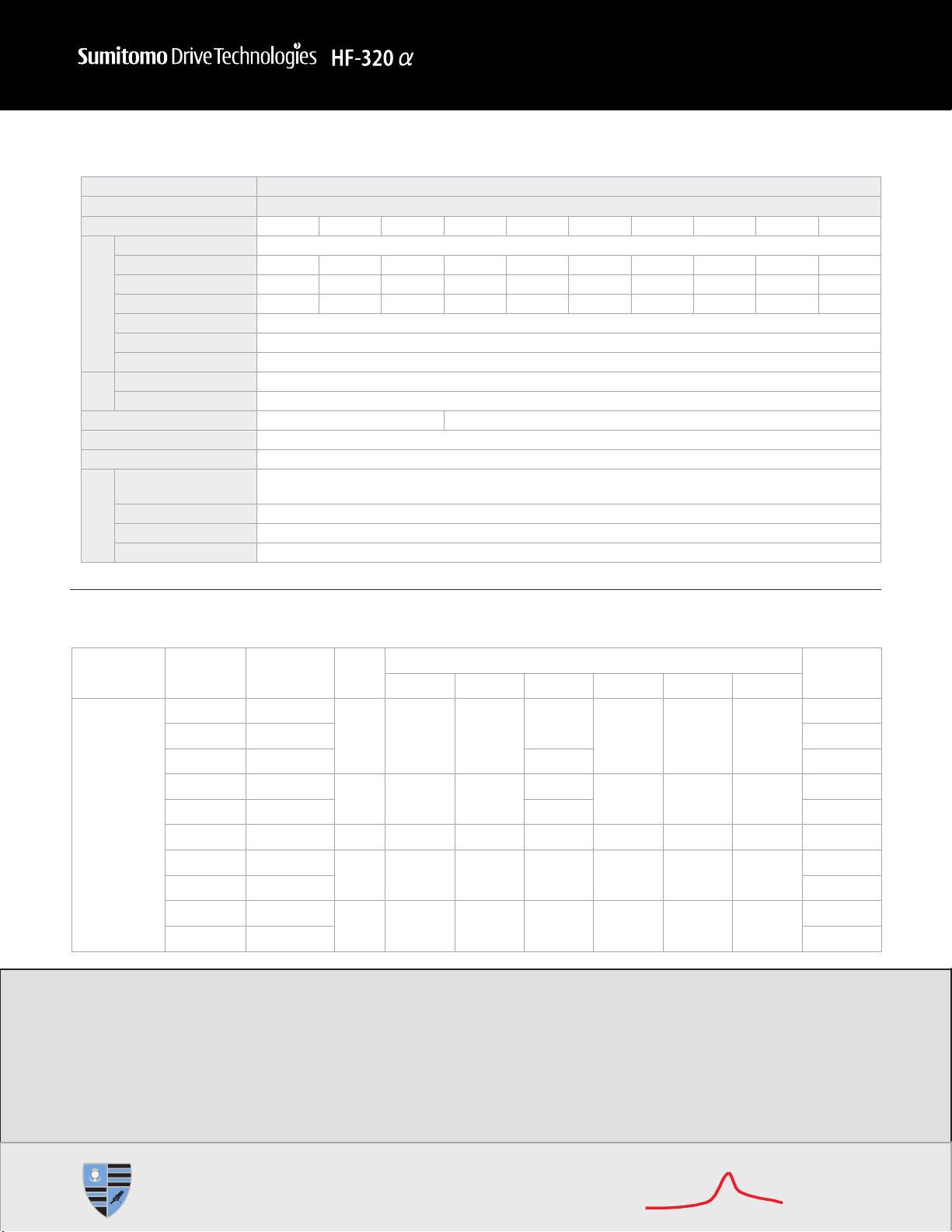
Item Specification
Input Voltage Class 3-Phase 200V
Motor HP (kW) 0.25 (0.2) 0.5 (0.4) 1 (0.75) 2 (1.5) 3 (2.2) 5 (3.7) 7.5 (5.5) 10 (7.5) 15 (11) 20 (15)
Rating
Type HF3212-
Motor Output A20 A40 A75 1A5 2A2 3A7 5A5 7A5 011 015
Capacity (kVA) [1] 0.6 1.3 1.8 3.1 4.2 6.7 10 13 21 25
Rated Output Current (A)[2] 1.6 (1.5) 3.3 (3.3) 5 (4.4) 8 (7.9) 11 (10) 17.5 (16.4) 27.5 (25) 33 (33) 54 (49) 66 (60)
Output Voltage [3] 3-phase 200V to 240V
Overload Current Rating 150% - 60 seconds, 200% - 0.5 seconds
Voltage Frequency 3-phase 200V to 240V - 50/60 Hz
Power
Supply
Allowable Fluctuation Voltage +10%, -15%[4], frequency ±5%
Protective Method IP20 enclosed type (JEM1030)
Cooling Method Self-cooling Forced air-cooled
Color Munsel 5Y-8/0.5
Built-in Filter RFI filter[5]
Environment
Atmosphere 2
Ambient Temperature -10°C to +50°C (above 40°C, remove the protective seal from the top of the inverter)
Storage Temperature -20°C to +65°C
Relative Humidity 20 to 93% (condensation free)
Notes:
[1] Capacity is calculated at 220V for the 200V class and at 440V for the 400V class.
[2] Indicates rated output current setting when the PWM carrier frequency (parameter F300) is 4kHz or less. When exceeding 4kHz, the rated output current setting is shown in parentheses
When the input power voltage of the 400V class model exceeds 480V, it is necessary to further reduce the setting. The default setting of the PWM carrier frequency is 12 kHz.
[3] Maximum output voltage is the same as the input voltage.
[4] ±10% when the inverver is used continuously (load of 100%).
[5] Built-in standard filter: Core and capacities; With RFI noise filter option: complies EN55011 Class AGroup 1 (Max. length of motor connecting cable 16.40 ft. or 5m) and Class B Group 1
(Max. length of motor connecting cable 3.28 ft. or 1m).
[6] in high-attenuation EMI filter: Complies EN55011 Class AGroup 1 (Max. length of motor connecting cable 16.40 ft. or 5m); With RFI noise filter option: complies EN55011 Class B
Group 1 (Max. length of motor connecting cable 65.62 ft. or 20m) and Class A Group 1(Max. length of motor connecting cable 164.04 FT OR 50 m.
Indoors; maximum altitude: 3,280.84 ft. (1000 m); not exposed to direct sunlight, corrosive or explosive gas,
vibration (less than 5.9m/s ) (10 to 55Hz)
Dimensions
Input Voltage Motor
HP (kW) Inverter Type Figure
Dimensions (mm) Approx.
Weight (kg)
W H D W1 H1 H2
3-phase 200V
0.25 (0.2) HF3212-A20
A 72 130 120 60 121.5 15
1.1
0.5 (0.4) HF3212-A40 1.2
1 (0.75) HF3212-A75 130 1.2
2 (1.5) HF3212-1A5 B 105 130 130 93 121.5 13 1.4
3 (2.2) HF3212-2A2 150 2.3
5 (3.7) HF3212-3A7 C 140 170 150 126 157 14 2.5
7.5 (5.5) HF3212-5A5 D 180 220 170 160 210 19.2 6.2
10 (7.5) HF3212-7A5 6.3
15 (11) HF3212-011 D*245 310 190 225 295 19.5 9.8
20 (15) HF3212-015 9.9
3-Phase 200V - 240V
Inverter
LOCHABER CORNWALL, INC.
LCI TPSI
Specifications
TD-3

■Sound Basic Functions
●With keypad and the frequency setting potentiometer on the
front panel, you can start operation easily and immediately.
●Every model has a regenerative braking circuit built-in, so only
an optional braking resistor needs to be connected if required.
●All three-phase and single-phase 200V models with a
capacity of 0.75kW or less are capable of self-cooling without
needing fans.
■Completely Noise-Proof
●An optional EMC plate can also be attached with a built-in
noise filter. This facilitates the wiring of shielded cables to
ground, and to the machine ground.
●If leakage current is a problem, disconnecting the grounding
capacitor can reduce it by simply pulling up a jumper switch
(Single-phase 200V and three-phase 400V models).
■
A Wide Variety of Input Terminal Functions
●Two analog input terminals can be used as logic input
terminals by changing parameter settings.
●If the two analog input terminals are switched over to logic
input terminals, up to eight contact input terminals can be
used at a same time.
●A function can be selected from among 65 functions and
assigned to each individual contact input terminal.
●With a slide switch, you can easily switch between sink logic
and source logic configurations.
●Power can be supplied from either the internal power supply
(24V) but also an external power supply (optional). In the
latter case, power is supplied through the PCS terminals.
■AGreat Variety of Output Terminals
●Three output terminals are provided: a relay contact output
terminal (1c), a relay contact terminal (1a) and an open
collector output terminal.
●The open collector output terminal (DRV-OM) completely
insulated from other terminals, which can also be used as a
pulse train output terminal.
●A function can be selected from 58 functions and assigned to
each individual output terminal.It is also possible to assign
two different functions to a single output terminal,
economizing on the use of terminals and cables.
●Analog output terminals can be be set for 0-10V, 0-1mA or 4-
20mA.
■Easy Selection and Installation
●Compact inverters with a wide range of capacities (0.2kW to
15kW) are available.
●Supporting a wide range of supply voltages:
240V class: 200V to 240V
500V class: 380V to 500V
Allowable fluctuations in voltage: +10%, -15%
●Operative in a wide range of ambient temperatures: -10°C to
+60°C (When the ambient temperature is 50°C and over, the
current needs to be reduced.)
■Dynamic Functions
●A dynamic energy saving mode specially designed for fan
motors provides substantial energy saving compared to
conventional modes.
●The energy saving effect can be checked easily by monitoring
integrated input and output kWh, in addition instantaneous
power.
●A dynamic quick deceleration control mode was added to
conventional deceleration modes achieving faster stopping
without using a braking resistor.
■AWide Choice of Monitor Menu Items
●A list of p to 20 parameters, including load current and torque
current, can be monitored during normal operation.
●Even if the inverter is tripped, monitoring of up to parameters
can continue until power is turned off.When power is turned
off, the last 10 parameters monitored at the occurrence of the
last four trips are retained.
●Up to 16 kinds of monitor menu items and up to 4 kinds of
outputs for adjustments can be assigned to the analog
terminals and the pulse train output terminals. Also,
adjustments can be made easily.
●A free-unit scaling function is provided so that various items,
such as the rotational speed and the line speed, can also be
displayed in addition to the operation frequency. Also, a bias
can be specified.
■Making Complicated Settings Easily
●With the automatic torque boost function, the motor can be
tuned easily for vector control. (The rated current, no-load
current and rated rotational speed of the motor need to be set
manually.)
●With the automatic acceleration/deceleration function, the
time can be set easily.
●With the automatic setting function, can be assigned easily to
input terminals on the terminal board.
●With the history function, a parameter that is used repeatedly
can be invoked and changed in one operation.
●Every HF-320Dinverter allows you to specify steps in which a
value changes each time a button on the operation panel is
pressed. For example, if you want to set the freguency by
steps of 10 Hz, this feature comes in very handy.
■Complete with Protective Functions
●All possible protective functions are provided to protect the
inverter and its peripheral devices.
●More than 30 kinds of information about causes of tripping and
more than 20 kinds of alarm information can be displayed.
●Every HF-320Dinverter has the function of protecting from
input/output open-phases detecting the breakage of analog
signal cables, and protecting from overcurrent, overvoltage
and overload.
■
Programmable for a Variety of Operations
●A PID control function is provided for every HF-320Dseries,
control devices are not required for PID control. It is also
possible to specify a control waiting time and to put out
command matching signals.
●Up to three different acceleration/deceleration times can be
set, so that the HF-320Dcan be put to a wide range of uses.
●A motor setting can be selected between two. It is possible to
select a base frequency, a voltage, an amount of torque
boost, a thermal protection level, a stall operation level, a V/F
pattern, and so on.
●The output frequency can be set within a range of up to 500Hz.
■
Complete with Communications Functions
●Terminal circuit boards are detachable and replaceable with a
large variety of optional circuit boards.
●An RS485 communications circuit board is optionally
available. It also suports Modbus RTU protocol.
●Optional software program enables you to set parameters
using a personal computer, you can easily check, read, edit,
write and save parameter settings.
●Using the block reading/writing function that was newly added to
communications functions, you can issue a command or
monitor the operating conditions more easily and more quickly.
●Communications circuit boards supporting DeviceNET,
LonWorks, and so on are on the drawing board.
Explanation of Function
3
TD-4
LCI FURNACES - TPSI

4
Before Using Our Inverters
■
Selecting the Capacity (Model) of the Inverter
Selection
●Capacity
Refer to the applicable motor capacities listed in the standard
specifications.
When driving a high-pole motor, special motor, or multiple
motors in parallel, select such an inverter that the sum of the
motor rated current multiplied by 1.05 to 1.1 is less than the
inverter's rated output current value.
●Acceleration/Deceleration Times
The actual acceleration and deceleration times of a motor
driven by an inverter are determined by the torque and
moment of inertia 2 of the load, and can be calculated by the
following equations.
The acceleration and deceleration times of an inverter can be
set individually. In any case, however, they should be set
longer than their respective values determined by the
following equations.
Acceleration time
ta = (JM+JL)u'N(sec)
9.56 u(TM+ TL)
Deceleration time
ta = (JM+JL)u'N(sec)
9.56 u(TB+ TL)
JM: Moment of inertia of motor (kg·m2)
JL:
Moment of inertia of load (kg
·
m
2
)
(converted
into value on motor shaft)
'N: Difference in rotating speed between before
and after acceleration or deceleration (min-1)
Conditions TL: Load torque (N·m)
TM:
Motor rated torque x 1.2-1.3 (N
·
m) [V/f control]
Motor rated torque x 1.5 (N·m) [Vector
operation control]
TB: Motor rated torque x 0.2 (N·m)
When a braking resistor or a braking resistor
unit is used:
Motor rated torque x 0.8-1.0 (N·m)
●Allowable Torque Characteristics
When a standard motor is combined with an inverter to
perform variable speed operation, the motor temperature
rises slightly higher than it normally does during commercial
power supply operation. This is because the inverter output
voltage has a sinusoidal (approximate) PWM waveform. In
addition, the cooling becomes less effective at low speed, so
the torque must be reduced according to the frequency.
When constant-torque operation must be performed at low speeds,
use an AF motor designed specifically for use with inverters.
Note 1. 100% of torque refers to the amount of torque that the motor
produces when it is running at a 60Hz-synchronized speed. The
starting torque is smaller in this case than that required when power
is supplied from a commercial power line. So, the characteristics of
the machine to be operated need to be taken into consideration.
Note 2. The maximum allowable torque at 50Hz can be calculated
approximately by multiplying the maximum allowable torque at a
base frequency of 60Hz by 0.8.
●Starting Characteristics
When a motor is driven by an inverter, its operation is
restricted by the inverter’s overload current rating, so the
starting characteristic is different from those obtained from
commercial power supply operation.
Although the starting torque is smaller with an inverter than
with the commercial power supply, a high starting torque can
be produced at low speeds by adjusting the V/f pattern torque
boost amount or by employing vector control. (200% in
sensorless control mode, though this rate varies with the
motor characteristics). When a larger starting torque is
necessary, select an inverter with a larger capacity and
examine the possibility of increasing the motor capacity.
■Harmonic Current and Influence to
Power Supply
●Harmonics are defined as sinusoidal waves that is multiple
freguency of commercial power (base frequency: 50Hz or
60Hz). Commercial power including harmonics has a
distorted waveform.
Some electrical and electronic devices produce distorted
waves in their rectifying and smoothing circuits on the input
side. Harmonics produced by a device influence other
electrical equipment and facilities in some cases (for example,
overheating of phase advancing capacitors and reactors).
■Measures for Suppressing Higher
Harmonics when Driving with Inverter
●Connecting a Reactor
Harmonic current leakage from the inverter may be suppressed
by connecting an input AC reactor (ACL) to the input side of
the inverter or DC reactor (DCL) to the DC section of the
inverter.
1. Input AC Reactor (ACL)
Used to improve the input power factor, reduce the harmonics,
and suppress external surge on the inverter power source
side.
2. DC Reactor (DCL)
DC reactor is more efficient on improving power factor for
inverter power source side. Use input AC reactor together,
for suppressing external surges.
Note: Refer to section on Peripheral Equipments, or Options for
measures on high frequency noise when using inverters.
0
0
20
40
60
80
100
120
140
160
180
200
10 20 30 40
Output Frequency (Hz)
Maximum torque
Maximum allowable continuous torque
50 60 70 80
Torque (%) (See Note 1.)
[An example of V/f
control at a base
frequency of 60 Hz]
TD-5
5
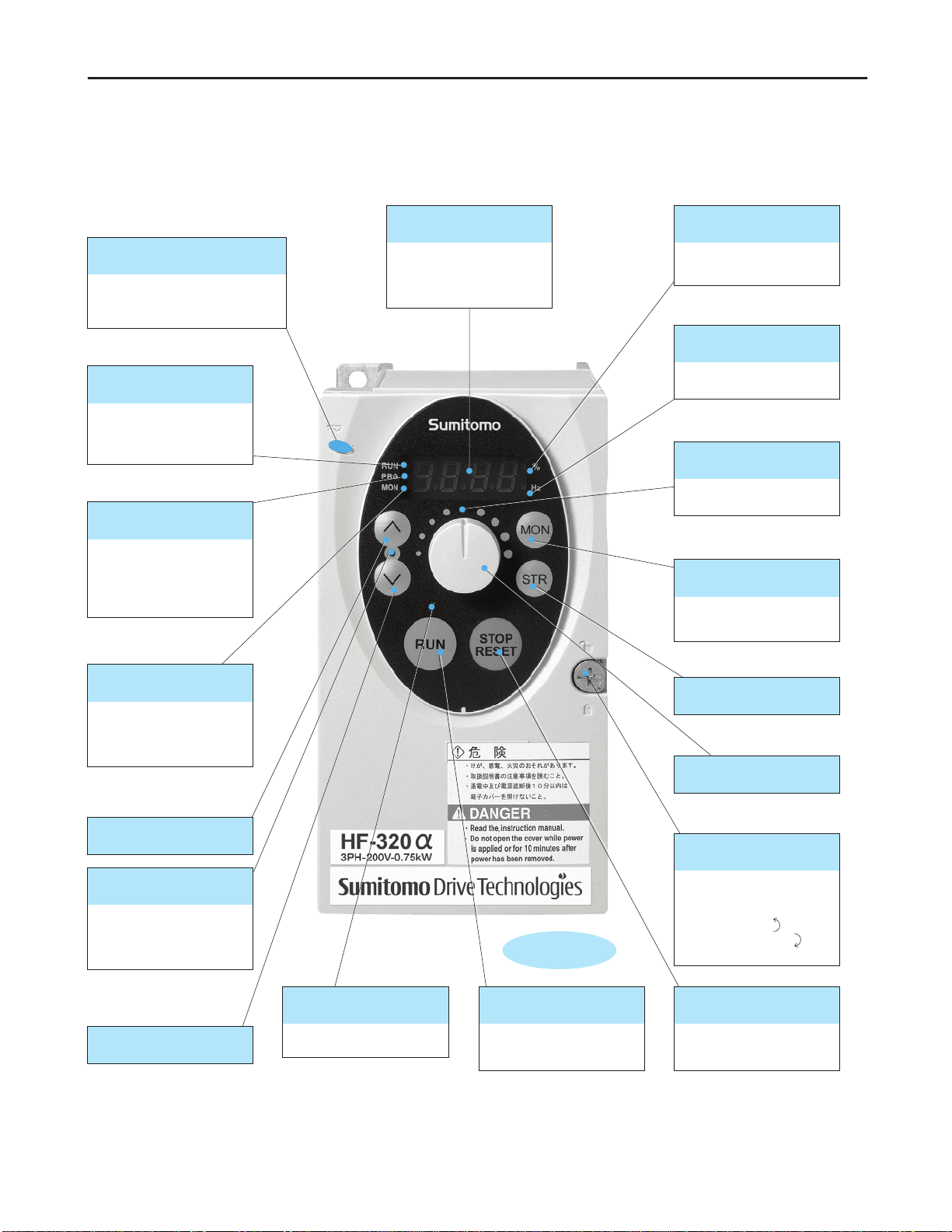
Operation
Full-scale
Displays the operation
frequency, a parameter, a
monitored item, the cause of
a failure, and so on.
■ Display
Lights when a numeric value
is displayed in %.
■ Percent (%) lamp
Lights when a numeric
value is displayed in Hz.
■ Hertz (Hz) lamp
Operation frequency can be
changed when lighted.
■
Built-in potentiometer lamp
Every pressing of this key while
the RUN key lamp is will cause
a slowdown stop.
■ STOP/RESET key
Displays operation
frequency, parameters, and
error causes.
■ Monitor (MON) key
Lights when an ON command
is issued but no frequency
signal is sent out. It blinks
when operation is started.
■ RUN lamp
Lights when the RUN key is
enabled.
■ RUN key lamp
Pressing this key while the RUN
key lamp is lighted starts
operation.
■ RUN key
Lights when the inverter is in
parameter setting mode. This
lamp blinks when the
parameter "AUH" or "Gr.U" is
selected.
■ PROGRAM lamp
Lights when the inverter is in
monitor mode. This lamp
blinks when a detailed past
trip record is displayed.
■ MONITOR lamp
■ Up key
■ Store (STR) key
■
Built-in potentiometer
■ Down key
Pressing up or down key
when this lamp is lighted
allows the setting of operation
frequency.
■ Up/Down key lamp Allows you to lock and unlock
the front panel easily.
Turn the screw 90°
counterclockwise to unlock,
or turn it 90° clockwise to lock
the front panel.
■
Front panel locking screw
Indicates that high voltage is still
present within the inverter. Do not
open the cover while this is lit.
■ CHARGE lamp
■Explanation of Operation Panel
TD-6
LCI FURNACES - TPSI

Operation
6
■How to Start and Stop
[Example of a CmOd setting procedure]
Key operated LED display Operation
0.0 Displays the operation frequency (operation stopped).
(When standard monitor display selection f710=0[Operation frequency])
auH Displays the first basic parameter [History (auH)].
CmOd Press either the or key to select "CmOd".
1Press STR key to display the parameter setting. (Default setting:1).
0Change the parameter to 0(terminal board) by pressing the key.
0CmOd Press the STR key to save the changed parameter. CmOd and the parameter set value
are displayed alternately.
■Start and Stop Using the Operation Panel Keys (CmOd=1)
Use the and keys on the operation panel to start and stop the motor.
: Motor starts.
: Motor stops.
■How to Set the Frequency
[Example of a fmOd setting procedure]
Key operated LED display Operation
0.0 Displays the operation frequency (operation stopped).
(When standard monitor display selection f710=0[Operation frequency])
auH Displays the first basic parameter [History (auH)].
fmOd Press either the or key to select "fmOd".
0Press STR key to display the parameter setting. (Default setting: 0).
3Change the parameter to 3(terminal board) by pressing the key.
3fmOd Press the STR key to save the changed parameter. fmOd and the parameter set value
are displayed alternately.
*Pressing the MON key twice returns the display to standard monitor mode (displaying operation frequency).
■
Setting the Frequency Using the Potentiometer on the Inverter Main Unit
(fmOd=0)
Set the frequency with the notches on the potentiometer.
Move clockwise for the higher frequencies.
The potentiometer has hysteresis. So the set value may slightly change when the inverter is turned off, and then turned back on.
STOP
RESET
RUN
STOP
RESET
RUN
MON
STR
STR
MON
STR
STR
TD-7
LCI FURNACES - TPSI

#
A?;0?90C3B7=)=7?A=@;8
1/3.?8BC2>>'
AB& 3B7=)=7?A=@;
;35AC@:A?+BC7:?88 1/3.?8BC2>>'
(33:=7?:BC&@A@9C,- ><2 ><* ><#4 6<4 2<2 1<# 4<4 #<4
1262/
(2> (*> (#4 6(4 2(2 1(# 4(4 #(4
"?3?7=A$C,'(-C%@ABC6 >< 6<1 6< 1<6 *<2 <# 6> 61
?AB0C@5A35AC7599B;A 6< 1<1 *< <> 66<> 6#<4 2#<4 11
,(-C%@ABC2 ,6<4- ,1<1- ,*<*- ,#<- ,6><>- ,6<*- ,24<>- ,11-
5A35AC@:A?+BC%@ABC1 1/3.?8BC2>>'CA@C2*>'
B9:@?0C7599B;AC9?A=;+ 64> />C8B7@;08C2>> /><4C8B7@;0
'@:A?+B/)9B5B;7$ 1/3.?8BC2>>'CA@C2*>'C/C4>>
(::@?:BC):57A5?A=@; '@:A?+BCC6> C/64 C%@ABC*C)9B5B;7$C4
9@AB7A=BC&BA.@0 2>C;7:@8B0CA$3BC,!6>1>-
"@@:=;+C&BA.@0 B:)/7@@:=;+ @97B0C?=9/7@@:B0
"@:@9 !5;8B:C4/><4
5=:A/=;C)=:AB9 ?8=7C)=:AB9C%@ABC4
1/3.?8BC*>>'
AB& 3B7=)=7?A=@;
;35AC@:A?+BC7:?88 1/3.?8BC*>>'
(33:=7?:BC&@A@9C,- ><* ><#4 6<4 2<2 *<> 4<4 #<4
126*/
(*> (#4 6(4 2(2 1(# 4(4 #(4
"?3?7=A$C,'(-C%@ABC6 6<6 6< 1<6 *<2 #<2 66 61
?AB0C@5A35AC7599B;A 6<4 2<4 *<6 4<4 <4 6*<1 6#
,(-C%@ABC2 ,6<4- ,2<6- ,1<#- ,4<>- ,<- ,61<>- ,6#-
5A35AC@:A?+BC%@ABC1 1/3.?8BC1>'CA@C4>>'
B9:@?0C7599B;AC9?A=;+ 64> />C8B7@;08C2>> /><4C8B7@;0
'@:A?+B/)9B5B;7$ 1/3.?8BC1>'CA@C4>>'C/C4>>
(::@?:BC):57A5?A=@; '@:A?+BCC6> C/64 C%@ABC*C)9B5B;7$C4
9@AB7A=BC&BA.@0 2>C;7:@8B0CA$3BC,!6>1>-
"@@:=;+C&BA.@0 @97B0C?=9/7@@:B0
"@:@9 !5;8B:C4/><4
5=:A/=;C)=:AB9 =+./?AAB;5?A=@;C!C)=:AB9C%@ABC
6/3.?8BC2>>'
AB& 3B7=)=7?A=@;
;35AC@:A?+BC7:?88 6/3.?8BC2>>'
(33:=7?:BC&@A@9C,- ><2 ><* ><#4 6<4 2<2
126/
(2> (*> (#4 6(4 2(2
"?3?7=A$C,'(-C%@ABC6 >< 6<1 6< 1<6 *<2
?AB0C@5A35AC7599B;A 6<4 1<1 *< <> 66<>
,(-C%@ABC2 ,6<4- ,1<1- ,*<*- ,#<- ,6><>-
5A35AC@:A?+BC%@ABC1 1/3.?8BC2>>'CA@C2*>'
B9:@?0C7599B;AC9?A=;+ 64> />C8B7@;08C2>> /><4C8B7@;0
'@:A?+B/)9B5B;7$ 1/3.?8BC2>>'CA@C2*>'C/C4>>
(::@?:BC):57A5?A=@; '@:A?+BCC6> C/64 C%@ABC*C)9B5B;7$C4
9@AB7A=BC&BA.@0 2>C;7:@8B0CA$3BC,!6>1>-
"@@:=;+C&BA.@0 B:)/7@@:=;+ @97B0C?=9/7@@:B0
"@:@9 !5;8B:C4/><4
5=:A/=;C)=:AB9 =+./?AAB;5?A=@;C!C)=:AB9C%@ABC
?A=;+
@B9
8533:$
?A=;+
@B9
8533:$
?A=;+
@B9
8533:$
%@ABC6< "?3?7=A$C=8C7?:75:?AB0C?AC22>'C)@9CA.BC2>>'C7:?88C?;0C?A
**>'C)@9CA.BC*>>'C7:?88<
%@ABC2< ;0=7?AB8C9?AB0C@5A35AC7599B;AC8BAA=;+C.B;CA.BC!C7?99=B9
)9B5B;7$C,3?9?&BAB9C1>>-C=8C*C@9C:B88<
.B;CB7BB0=;+C*CA.BC9?AB0C@5A35AC7599B;AC8BAA=;+C=8
=;0=7?AB0C=;CA.BC3?9B;A.B8=8<C.B;CA.BC=;35AC3@B9C@:A?+B
@)CA.BC*>>'C7:?88C&@0B:CB7BB08C*>'C=AC=8C;B7B88?9$CA@
)59A.B9C9B057BCA.BC8BAA=;+<C.BC0B)?5:AC8BAA=;+C@)CA.BC!
7?99=B9C9B5B;7$C=8C62<
%@ABC1< !?=&5&C@5A35AC@:A?+BC=8CA.BC8?&BC?8CA.BC=;35AC@:A?+B<
%@ABC*< 6> C.B;CA.BC=;B9AB9C=8C58B0C7@;A=;5@58:$C,:@?0C@)
6>> -<
%@ABC4< 5=:A/=;C8A?;0?90C)=:AB9C"@9BC?;0C7?3?7=A=B8
=A.CC;@=8BC)=:AB9C@3A=@;C"@&3:=B8C%44>66C":?88C(
9@53C6,!?<4&-C?;0C":?88CC9@53C6,!?<6&-
B;+A.C@)C&@A@9C7@;;B7A=;+C7?:B<
%@ABC< 5=:A/=;C.=+./?AAB;5?A=@;C!C)=:AB9
"@&3:=B8C%44>66C":?88C(C9@53C6,!?<4&-
=A.CC;@=8BC)=:AB9C@3A=@;C"@&3:=B8C%44>66C":?88C
9@53C6,!?<2>&-C?;0C":?88C(C9@53C6,!?<4>&-
B;+A.C@)C&@A@9C7@;;B7A=;+C7?:B<
$3BC@9&
$3BC@9&
$3BC@9&
TD-8
LCI FURNACES - TPSI

8
Common Specification
Item Specification
Control system Sinusoidal PWM control
Rated output voltage Adjustable within the range of 50 to 600V by correcting the supply voltage (not adjustable above the input voltage)
Output frequency range 0.5 to 500.0Hz, default setting: 0.5 to 80Hz, maximum frequency: 30 to 500Hz
Minimum setting steps of frequency
0.1Hz: operation panel setting, 0.2Hz: analog input (when the max. frequency is 100Hz).
Frequency accuracy Digital setting: within ±0.01% of the max. frequency (-10 to +60°C)
Analog setting: within ±0.5% of the max. frequency (25 C ±10°C)
Voltage/frequency characteristics
V/f constant, variable torque, automatic torque boost, vector control, automatic energy-saving, dynamic automatic energy-
saving control. Auto-tuning. Base frequency (25 - 500Hz) adjusting to 1 or 2, torque boost (0 - 30%) adjusting to 1 or 2,
adjusting frequency at start (0.5 - 10Hz)
Frequency setting signal Potentiometer on the front panel, external frequency potentiometer (connectable to a potentiometer with a rated impedance
of 1 - 10k ), 0 - 10Vdc (input impedance: VRF/VRF2=30k:), 4 - 20mAdc (Input impedance: 250 ).
Terminal board base frequency
The characteristic can be set arbitrarily by two-point setting. Possible to set individually for three functions: analog input
(VRF and VRF2) and communication command.
Frequency jump Three frequencies can be set. Setting of the jump frequency and the range.
Upper- and lower-limit frequencies
Upper-limit frequency: 0 to max. frequency, lower-limit frequency: 0 to upper-limit frequency
PWM carrier frequency Adjustable within a range of 2.0 to 16.0Hz (default: 4kHz).
PID control Setting of proportional gain, integral gain, differential gain and control wait time. Checking whether the amount of processing
amount and the amount of feedback agree.
Acceleration/deceleration time
Selectable from among acceleration/deceleration times 1, 2 or 3 (0.0 to 3200 sec.). Automatic acceleration/deceleration function.
S-pattern 1 or 2, and S-pattern value adjustable. Forced rapid deceleration and dynamic rapid deceleration function.
DC braking Braking start-up frequency: 0 to maximum frequency, braking rate: 0 to 100%, braking time: 0 to 20 seconds, emergency DC
braking, motor shaft fixing control
Dynamic braking Control and drive circuit is built in the inverter with the braking resistor outside (optional).
Input terminal function Possible to select from among 65 functions, such as forward/reverse run signal input, jog run signal input, operation base
signal input and reset signal input, to assign to 8 input terminals. Logic selectable between sink and source.
Output terminal functions
Possible to select from among 58 functions, such as upper/lower limit frequency signal output, low speed detection signal
output, specified speed reach signal output and failure signal output, to assign to FL relay output, open collector output and
RY output terminals.
Forward/reverse run
The RUN and STOP/RESET keys on the operation panel are used to start and stop operation, respectively. The switching between
forward run and reverse run can be done from one of the three control units: operation panel, terminal board and external control unit.
Jog run Jog mode, if selected, allows jog operation from the operation panel or the terminal board.
Preset speed operation Base frequency + 15-speed operation possible by changing the combination of 4 contacts on the terminal board.
Retry operation Capable of restarting automatically after a check of the main circuit elements in case the protective function is activated. 10
times (Max.) (selectable with a parameter)
Various prohibition settings
Possible to write-protect parameters and to prohibit the change of panel frequency settings and the use of operation panel
for operation, emergency stop or resetting.
Regenerative power ride-through control
Possible to keep the motor running using its regenerative energy in case of a momentary power failure. (Default: OFF)
Auto-restart operation In the event of a momentary power failure, the inverter reads the rotational speed of the coasting motor and outputs a
frequency appropriate to the rotational speed in order to restart the motor smoothly. This function can also be used when
switching to commercial power.
Drooping function When two or more inverters are used to operate a single load, this function prevents load from concentrating on one inverter
due to unbalance.
Override function The sum of two analog signals (VRF/VRF2) can be used as a frequency command value.
Failure detection signal 1c-contact output: (250Vac-0.5A-cos I= 0.4)
Protective function Stall prevention, current limitation, over-current, output short circuit, over-voltage, over-voltage limitation, undervoltage,
ground fault, power supply phase failure, output phase failure, overload protection by electronic thermal function, armature
over-current at start-up, load side over-current at start-up, over-torque, undercurrent, overheating, cumulative operation time,
life alarm, emergency stop, braking resistor over-current/overload, various pre-alarms
Electronic thermal characteristic
Switching between standard motor and constant-torque AF motor, switching between motors 1 and 2, setting of overload trip
time, adjustment of stall prevention levels 1 and 2, selection of overload stall
Reset function Function of resetting by closing contact 1a or by turning off power or the operation panel. This function is also used to save
and clear trip records.
Alarms Stall prevention, overvoltage, overload, under-voltage, setting error, retry in process, upper/lower limits
Causes of failures Over-current, overvoltage, overheating, short-circuit in load, ground fault, overload on inverter, over-current through arm at
start-up, over-current through load at start-up, CPU fault, EEPROM fault, RAM fault, ROM fault, communication error.
(Selectable: Over-current through braking resistor/overload, emergency stop, under-voltage, low voltage, over-torque, motor
overload, output open-phase)
Monitoring function Operation frequency, operation frequency command, forward/reverse run, output current, voltage in DC section, output
voltage, torque, torque current, load factor of inverter, integral load factor of PBR, input power, output power, information on
input terminals, information on output terminals, version of CPU1, version of CPU2, version of memory, PID feedback
amount, frequency command (after PID), integral input power, integral output power, rated current, causes of past trips 1
through 4, information on life alarm, cumulative operation time
Past trip monitoring function
Stores data on the past four trips: number of trips that occurred in succession, operation frequency, direction of rotation, load
current, input voltage, output voltage, information on input terminals, information on output terminals, and cumulative
operation time when each trip occurred.
Output for frequency meter
Analog output (1mAdc full-scale DC ammeter or 7.5Vdc full-scale DC voltmeter/rectifier type AC voltmeter, 4 to 20mA/0 to
20mA output)
4-digit 7-segments LED Frequency: inverter output frequency.
Alarm: stall alarm "C", overvoltage alarm "P", overload alarm "L", overheat alarm "H".
Status: inverter status (frequency, cause of activation of protective function, input/output voltage, output current, etc.) and
parameter settings.
Free-unit display: arbitrary unit (e.g. rotating speed) corresponding to output frequency.
Indicator Lamps indicating the inverter status by lighting, such as RUN lamp, MON lamp, PRG lamp, % lamp, Hz lamp, frequency
setting potentiometer lamp, UP/DOWN key lamp and RUN key lamp. The charge lamp indicates that the main circuit
capacitors are electrically charged.
Use environments
Indoor, altitude: 1000m (Max.), not exposed to direct sunlight, corrosive gas, explosive gas / vibration (less than 5.9m/s2) (10 to 55Hz)
Ambient temperature -10 to +50°C Note 1
Storage temperature -25 to +65°C
Relative humidity 20 to 93% (free from condensation and vapor).
Note 1. Above 40°C : Remove the protective seal from the top of the inverter.
Environments
Display function Protective function Operation specifications Principal control functions
(programmable)
(programmable)

9
Protective Functions
Error code Problem Possible causes
Overcurrent during
acceleration
Overcurrent flowing
in element during
acceleration
Overcurrent during
deceleration
Overcurrent flowing
in element during
decelearion
Overcurrent during
constant speed operation
Overcurrent flowing in
element during operation
Ground fault trip
Arm overcurrent at
start-up(for 11 and
15 kW models only)
Overcurrent (An
overcurrent on the
load side at start-up)
Arm overcurrent at
start-up
Input phase failure
Output phase failure
Overvoltage during
acceleration
Overvoltage during
deceleration
Overvoltage during
constant-speed
operation
Inverter overload
Motor overload
Error code Problem Possible causes
Dynamic braking
resistoroverload trip
Over-torque trip
Overheat
External thermal trip
Emergency stop
EEPROM fault 1
EEPROM fault 2
EEPROM fault 3
Main unit RAM fault
Main unit ROM fault
CPU fault 1
Remote control
error
Current detector
fault
Optional circuit
board format error
Low-current
operation
Trip
Undervoltage
trip(main circuit)
Ground fault trip
Auto-tuning error
Invertertype error
Brea in analog
signal cable
CPU
communications
error
Excessive torque
boosted
CPU fault 2
OL 1
OC IP
OC2
OC2P
OC3
OC3P
OC1P
OC2P
OC3P
OCL
OCA
*
EPHI
*
EPHO
OPI
OP2
OP3
OL1
OL2
OLr
*
Ot
OH
OH2
E
EEP1
EEP2
EEP3
Err2
Err3
Err4
Err5
Err7
Err8
*
UC
*
UPI
EF2
etnI
etyp
*
E-18
E-19
e-20
e-21
· The acceleration time acc is too short.
· The V/F setting is improper.
· A restart signal is imput to the rotating
motor after a momentary stop, etc.
· A special motor (e.g. motor with a small
impedance) is used.
· The deceleration time dec is too short.
· The load fluctuates abruptly.
· The load is in an abnormal condition.
· A current leaked from an output cable or
the motor to ground.
· A main circuit elements is defective.
· The insulation of the output main circuit or
motor is defective.
· The motor has too small impedance.
· A 11 or 15 kW model was started,
although a current is leaked from an
output cable or the motor to ground.
· A main circuit elements is defective.
· A phase failure occured in the input line of
the main circuit.
· The capacitor in the main circuit lacks
capacitance.
· A phase failure occurred in the output line
of the main circuit.
· The imput voltage fluctuates abnormally.
1. The power supply has a capacity of
200kVA or more.
2. A power factor improvement capacitor
is opened or closed.
3.
A system using a thyrister is connected
to the same power distribution line.
· A restart signal is input to the rotating
motor after a momentary stop, etc.
· The deceleration time dec is too short.
(Regenerative energy is too large.)
·f304 (dynamic braking resistor) is off.
·f305 (overvoltage limit operation) is off.
· The input voltage fluctuates abnormally.
1. The power supply has a capacity of
200kVA or more.
2. A power factor improvement capacitor
is opened and closed.
3. A system using a thyrister is connected
to the same power distribution line.
· The input voltage fluctuates abnormally.
1. The power supply has a capacity of
200kVA or more.
2. A power factor improvement capacitor
is opened or closed.
3. A system using a thyrister is connected
to the same power distribution line.
· The motor is in a regenerative state
because the load causes the motor to run
at a frequency higher than the inverter
output frequency.
· The acceleration time ACC is too short.
· The DC braking amout is too large.
· The V/F setting is improper.
· A restart signal is input to the rotating
motor after a momentary stop, etc.
· The load is too large.
· The V/F setting is improper.
· The motor is locked up.
· Low·speed operation is performed
continuously.
· An excessive load is applied to the motor
during operation.
· The deceleration time is too short.
· Dynamic braking is too large.
· Over-torque reaches to a detection level
during operation.
· The cooling fan does not rotate.
· The ambient temperature is too high.
· The vent is blocked up.
· A heat generating device is installed close
to the inverter.
· The thermistor in the unit is broken.
· An external thermal trip is input.
· During automatic operation or remote
operation, a stop command is entered
from the operation panel or a remote input
device.
· A data writing error occurs.
· Power supply is cut off during typ
operation and data writing is aborted.
· A data reading error occurred.
· The control RAM is defective.
· The control ROM is defective.
· The control CPU is defective.
· An error arises during remote operation.
· The current detector is defective.
· An optional circuit board in a different
format is installed.
· The output current decreased to a low-
current detection level during operation.
· The input voltage (in the main circuit) is
too low.
· A ground fault occurs in the output cable
or the motor.
· Check the motor parameter f401 to f494.
· The motor with the capacity of 2 classes
or less than the inverter is used.
· The output cable is too thin.
· The motor is rotating.
· The inverter is used for loads other than
those of three-phase induction motors.
· Circuit board is changed. (Or main
circuit/drive circuit board)
· The signal input via VRF is below the
analog sinal detectio level set with f633.
· A communications error occurs between
control CPUs.
· The torque boost parameter vb is set too
high.
· The motor has too small impedance.
· The control CPU is defective.
TD-10
LCI FURNACES - TPSI

10
Terminal Functions
■Main Circuit Teminal Functions
Terminals symbol Terminal function
Grounding terminal for connecting inverter. There are 3 terminals in total. 2 terminals in the terminal board, 1
terminal in the cooling fin.
200V class: single-phase 200~240V-50/60Hz *Single-phase input: R/L1 and S/L2 terminals
R/L1, S/L2, T/L3 3-phase 200~240V-50/60Hz
400V class: 3-phase 380~500V-50/60Hz
U/T1, V/T2, W/T3 Connect to a (three-phase induction) motor.
P(+), PR Connect to braking resistors. Change parameters f304,f305,f309, if necessary.
N(-) This is a negative potential terminal in the internal DC main circuit. DC common power can be input across
the P(+) terminals (positive potential).
P1, P(+) Terminals for connecting a DC reactor (DCL: optional external device). Shorted by a short bar when shipped
from the factory. Before installing DCL, remove the short bar.
■Control Circuit Terminal Functions
Multifunction programmable
contact input
Shorting across FR-COM causes forward rotation; open
causes slowdown and stop.
Shorting across FR-COM causes reverce rotation; open
causes slowdown and stop.
Shorting across RST-COM causes a held reset when the
inverter protector function is operating. Note that when
the inverter is operating normally, it will not operate even
if there is a short across RST-COM.
Shorting across DFL-COM causes preset speed operation.
Shorting across DFM-COM causes preset speed operation.
Shorting across DFH-COM causes preset speed opera
tion.
Terminal
symbol
FR
RR
RST
DFL
DFM
DFH
PCS External 24Vdc power input
Control circuit's equipotential terminal (sink logic).3 common
terminals for input/output.
24Vdc (Insulation resistance: 50Vdc)
10Vdc (permissible load current: 10mAdc)
10Vdc (internal impedance: 30k:)
4~20mA (Internal impedance: 250:)
10Vdc (internal impedance: 30k:)
1mA full-scale DC ammeter or 7.5Vdc
1mA full-scale
DC voltmeter
0-20mA (4-20mA) full-scale
DC ammeter
24Vdc - 100mA
Open collector output:
24Vdc - 50mA
Pulse train output
10mA or more
250Vac - 1A: at resistance load
30Vdc - 0.5A, 250Vac - 0.5A
(cosI= 0.4)
Dry contact input
24Vdc - 5mA or less
*Sink/Source/PCS
selectable using SW
COM
Power output for analog input setting.
+V Multifunction programmable analog input. Standard default
setting: 0-10Vdc input and 0-60Hz frequency. The function can
be changed to 4-20 mAdc (0-20 mA) current input by flipping
the VRF slide switch to the I position.
Multifunction programmable analog input. Standard default
setting: 0-10Vdc input and 0-50Hz (50Hz setting) or 0-60Hz
(60Hz setting) frequency.
Multifunction programmable analog output.
Standard default setting: output freguency. Connect a 1mAdc
full-scale ammeter or 7.5Vdc (10Vdc)-1mA full-scale voltmeter.
The function can be changed to 0-20mAdc (4-20mA) current
output by flipping the FRQ slide switch to the I position.
VRF
VRF2
FRQ
When the source logic is used, a common terminal 24Vdc is
connected.
P24V
Multifunction programmable open collector output. Standard
default settings detect and output speed reach signal output
frequencies.
The OM terminal is an isoelectric output terminal. It is insulated
from the COM terminal.
These terminals can also be used as multifunction
programmable pulse train output terminals.
DRV
OM
Multifunction programmable relay contact output.
Contact ratings: 250Vac - 2A (cos = 1), 30Vdc - 1A, 250Vac -
1A (cos = 0.4).
Standard default settings detect and output low-speed signal
output frequencies.
RC
RY
250Vac - 1A: at resistance load
30Vdc - 0.5A, 250Vac - 0.5A
(cosI= 0.4)
Multifunction programmable relay contact output.
Contact ratings: 250Vac-1A (cos = 1), 30Vdc-0.5A, 250Vac-
0.5A (cos = 0.4).
Detects the opertion of the inverter’s protection function.
Contact across FA-FC is closed and FB-FC is opened during
protection function operation.
FA
FB
FC
Note 1
Note 1
Note 2
Note 2
Electrical specifications Wire sizeFunction
Solid wire : 0.3 to 1.5 (mm2)
Stranded wire :
0.3 to 1.5 (mm2)
(AWG22 to 16)
Sheath strip length : 6 (mm)
Screwdriver:
Small-sized flat-blade screwdriver
Blade thickness:
0.4 mm or less
Blade width: 2.5 mm or less
Note 1: By changing parameter setting, this terminal can also be used as a multifunction programmable contact input terminal.
When the inverter is used in a sink logic configuration, a resistor (4.7k at 0.5W) should be inserted between the P24 and VRF/VRF2 terminals.
Also, the slide switch for the VRF terminal needs to be turned to the V position.
Note 2: Multifunction output terminals to which two different functions can be assigned.
TD-11
11
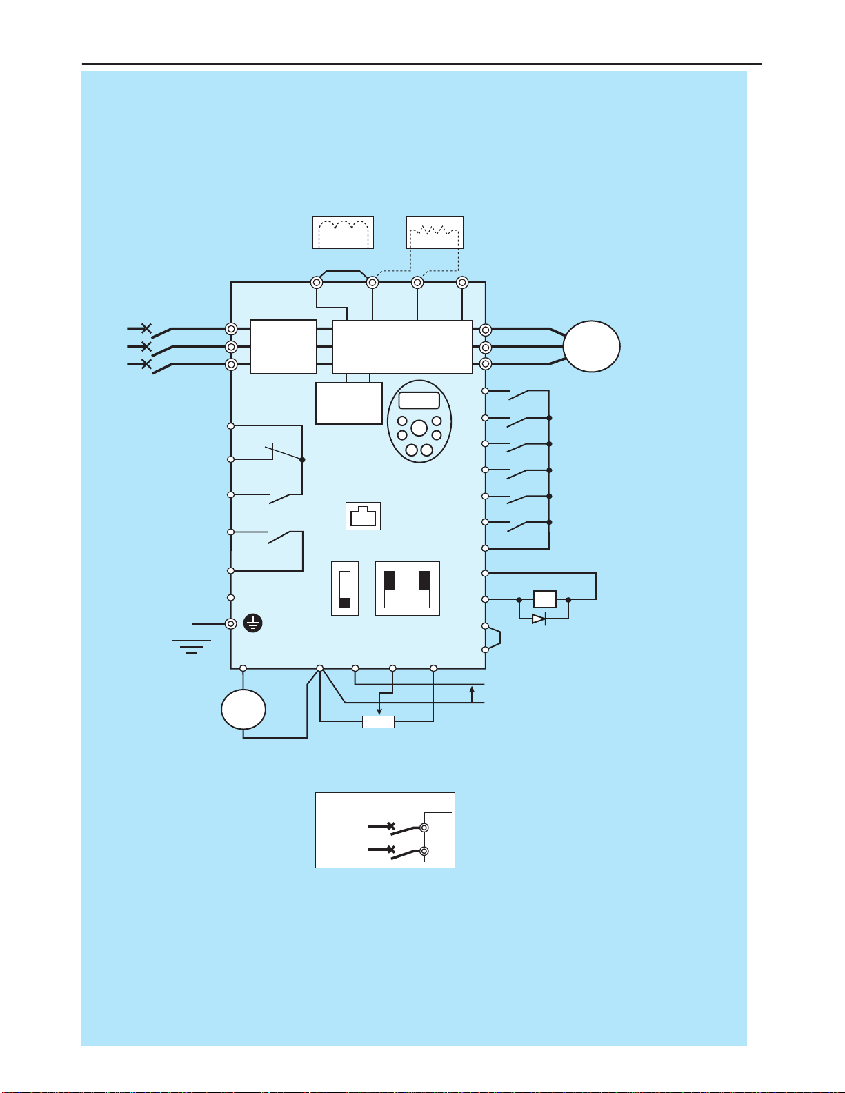
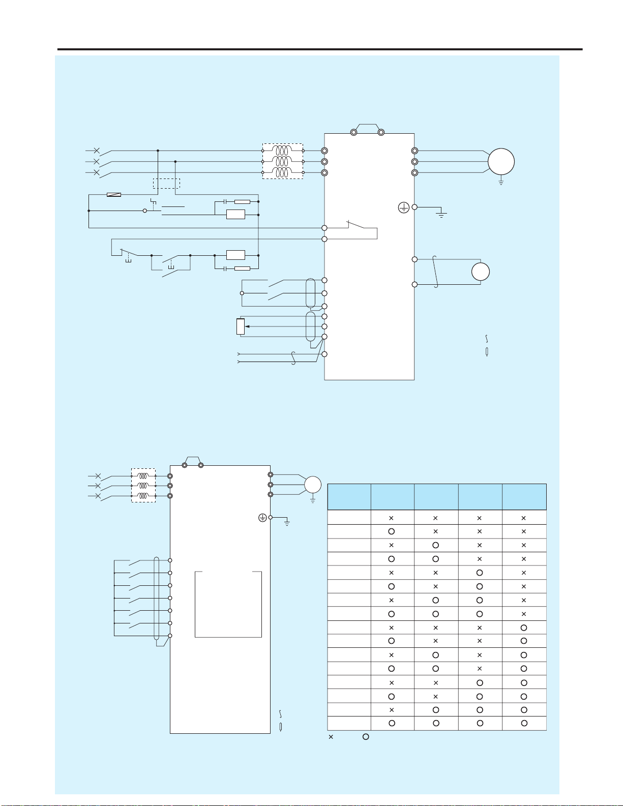
Standard Connection Diagram
MCCB
*1
R/L1
S/L2
T/L3
U/T1
V/T2
W/T3 I M
FC
FB
FA
RY
PCS
RC
Motor
FR
RR
RST
DFL
DFM
DFH
COM
P24V
DRV
OM
COM
FRQ
PCS
COM VRF VRF2 +V
++
−
−
P1 P(+) PR N(-)
Voltage signal: 0-10V
(Current signal: 4-20mA)
External potentiometer (1-10kΩ)
(or input voltage signal across VRF2-COM terminals: 0-10V)
Control
circuit
Operation
panel
Fault detection relay
Ry
HF-320α
Frequency
meter
(ammeter)
Main circuit
Noise
filter
DC reactor (DCL)
*2 (option)
Connector for
common serial
communications
Foward
Reverse
Reset
Preset-speed 1
Preset-speed 2
Preset-speed 3
Common
Braking resistor (option)
MCCB (2P)
R/L1
S/L2
Power supply
1φ200~240V
-50/60HZ
Speed reach
signal output
I ISINK
SW1
SOURCE
FRQ
VVRF
V
Main circuit power supply
200V class: 3-phase
200-240V -50/60Hz
400V class: 3-phase
380-500V -50/60Hz
*3
Low-speed
signal output
*1: The T/L3 terminal not providedfor signal-
phase models.
Use the R/L1 and S/L2 terminal as input
terminals.
*2: The inverter came with the P1 and the P(+)
terminals shorted by means of a shoeting
bar.
Before installing the DC reactor (DCL),
remove the bar.
*3: When using the DRV output terminal in sink
logic mode, short-circuit the OM and COM
terminals.
■Sink (Negative) Logic: Common = COM
TD-12
LCI FURNACES - TPSI
12
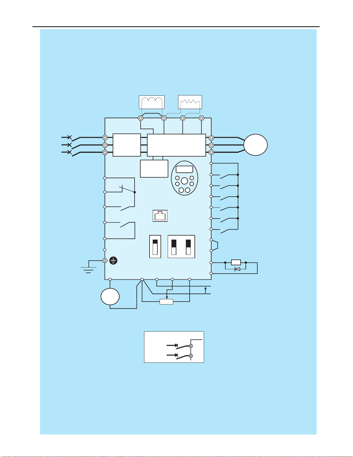
Standard Connection Diagram
MCCB
*1
R/L1
S/L2
T/L3
U/T1
V/T2
W/T3 I M
FC
FB
FA
RY
RC
P24V
FR
RR
RST
DFL
DFM
DFH
P24V
DRV
OM
COM
P1
MCCB(2P)
R/L1
S/L2
FRQ COM VRF VRF2 +V
PCS
P(+) PR N(-)
I ISINK
SW1
SOURCE
FRQ
VVRF
V
*3
Ry
PCS
Motor
++
−
−Voltage signal: 0-10V
(Current signal: 4-20mA)
External potentiometer (1-10kΩ)
(or input voltage signal across VRF2-COM terminals: 0-10V)
Control
circuit
Operation
panel
Fault detection relay HF-320α
Frequency
meter
(ammeter)
Main circuit
Noise
filter
DC reactor (DCL)
*2 (option)
Connector for
common serial
communications
Foward
Reverse
Reset
Preset-speed 1
Preset-speed 2
Preset-speed 3
Braking resistor (option)
Power supply
1φ200~240V
-50/60HZ
Speed reach
signal output
Main circuit power supply
200V class: 3-phase
200-240V -50/60Hz
400V class: 3-phase
380-500V -50/60Hz
Low-speed
signal output
*1: The T/L3 terminal not providedfor signal-
phase models.
Use the R/L1 and S/L2 terminal as input
terminals.
*2: The inverter came with the P1 and the P(+)
terminals shorted by means of a shoeting
bar.
Before installing the DC reactor (DCL),
remove the bar.
*3: When using the OM output terminal in
source logic mode, short-circuit the P24V
and DRV terminals.
■Source (Positive) Logic: Common = P24
TD-13
LCI FURNACES - TPSI
13
Applied Connection Diagram
P P1
ACL
U
V
W
X
Y
Z
MCCB
Tx
FU
RN
Run
Stop
RN
RN
AU
AU FB
FC
COM
+V
COM
VRF
+
-
+
FM
−
FRQ
COM
IM
HF-320α
R/L1
S/L2
T/L3
U/T1
V/T2
W/T3
(+)
Note 4
Manual
(Speed setting unit)
Auto (Current signal)
FR Note 1
2DF Note 3
VRF Note 2
Note 1: Set parameter CMOD to “0: Terminal board”
Note 2: Set parameter FMOD to “2: VRF2.” Set Parameter F201 to "1: VRF." and set switch VRF on 1 side.
Note 3: Set parameter F114 to “38: Frequency command forced awitching to F207”
Note 4: Install a step-down transformer when the power is 400 V-class.
Speed setting unit
1kΩ
Current signal
DC4–20mA
Frequency counter
10V F.S.
Ground
TH (Note)
: Twisted wire
: Shielded wire
Power
■Operation by Current Signal (4-20 mADC)
When terminal DFL is used as a current/voltage signal (speed setting unit) changeover signal
input.
■Multispeed Operation (16-Step Speed)
MCB P1
P
IM
FR
RR
DFL
DFM
DFH
RST
COM
F114=6
CMOD=0
F115=7
F116=8
F113=9
FC
Sr2
Sr1
Sr3
Sr4
Sr5
Sr6
Sr7
F287
F288
F289
F290
F291
F292
F293
F294
U X
Y
Z
V
W
HF-320α
R/L1
S/L2
T/L3
U/T1
V/T2
W/T3
(+)
Power
Forward rotation
Multi-stage speed 1
Multi-stage speed 2
Multi-stage speed 3
Multi-stage speed 4
TH
: Twisted wire
: Shielded wire
Multi-stage speed 1
Parameter setting
Multi-stage speed 2
Multi-stage speed 3
Multi-stage speed 4
Frequency
setting Multi-stage
speed
2
Multi-stage
speed
1
Multi-stage
speed
3
Multi-stage
speed
4
Frequency setting by external signal
(: Open, : Closed)
TD-14
LCI FURNACES - TPSI
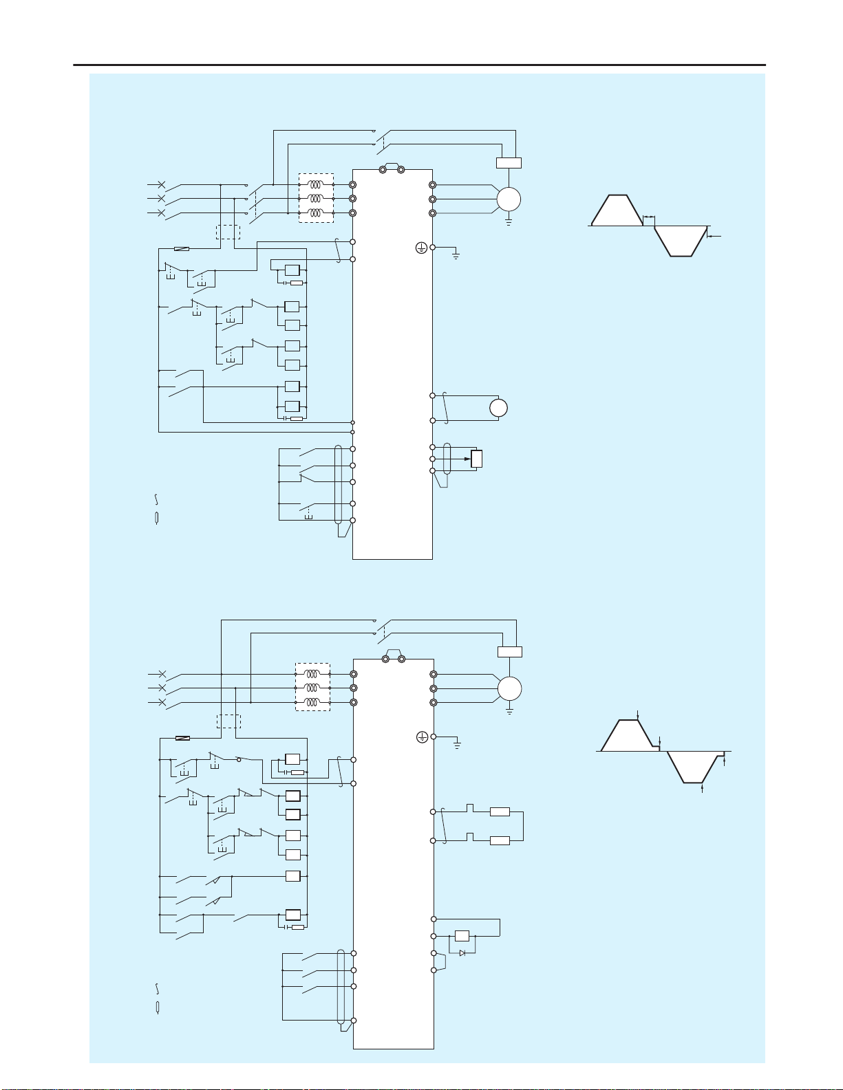
MCCB ACL
BR
R/L1
X
U
YV
Z
W
S/L2
T/L3
FB
FC
U/T1
V/T2 IM
Br
W/T3
OFF
FU
ON
MC R
F
R
F
FX FR
RR
DFL
RST
COM
RX
BX
F
R
MC
F
FX
R
RX
BX
BR
MC
MC
+
FM
FRQ
COM −
+V
VRF
COM
HF-320α
PP1
(+)
RC
RY
Power
Preparation
for operation
Stop
Normal
rotation
Reverse
rotation
Note 2
Note 3
Reset
Frequency
counter
10V F.S.
Tx
Note 1
Speed setter
1kΩ
Note 1: When the power supply is a 400
V class, install a step-down
transformer.
Note 2: Set parameter F114 to 54.
Note 3: Set parameter F130 to 14.
: Twisted wire
: Shielded wire
Brake
Brake
Normal
rotation
Reverse
rotation
Operation pattern
MCCB ACL
BR
XU
YV
Z
W
FB
FC
IM
Br
P
PR
FU
R
LS2
LS4
F
R
F
FX FR
RR
DFL
COM
RX
DF
FLS1
R
F
R
LS3
F
FX
R
RX
DF
BR
Tx
LS1
HF-320α
LS2
LS1, LS3
LS3
LS4
P P1
THR
MC
MC
ON
MC
OFF THR
UPF
R/L1
S/L2
T/L3
U/T1
V/T2
W/T3
(+)
(+)
Power
Note 1
Stop
Normal
rotation
Reverse
rotation
Note 2
Note 4
Tx
Note 3
: Twisted wire
: Shielded wire
Normal
rotation
Normal
rotation
Operation pattern
Braking resistor
The limit switch is a
holding type.
Preparation
for operation
Note 1: Use inflammable cable for
braking resistor wiring.
Note 2: Parameter Sr1 is for
slow-speed frequency setting
and FC is for high-speed
setting.
Note 3: When the power supply is a
400 V class, install a
step-down transformer.
Note 4: Set parameter F131 to 4 and
adjust the braking timing by
F100 .Parameters F100
should be set at approx. 2 Hz
usually.
P24V
OM
DRV
COM
UPF
TD-15

15
Table of Parameters
■Usage Information
■Basic Parameters
●Operational Frequency Parameter
FC 0.0
●4 Automatic Functions
AUH -
AU1 0
AU2 0
AU4 0
●Other Basic Parameters
CMOd 1
FMOd 0
FMSL 0
FM -
TyP 0
Fr 0
ACC 10.0
dEC 10.0
FH 60.0
UL 60.0
LL 0.0
VL 60.0
VLV 200/400
Title Function Adjustment range
Default setting
Note
Item Contents Item Contents
Date of setting/Name Customer name/End user name
Combined machine/Application
Machine nomenclature/product number
Motor manufacturer/Nomenclature
Motor capacity/Ratings
Inverter nomenclature/quantity HF-321-
Inverter product number/Serial number
Usage option Peripheral equipment used
Used control terminal blockNote P24V, DRV, OM, FRQ, COM, FA, FB, FC, +V, VRF, VRF2, COM, PCS, DFL, DFM, DFH, FR, RR, RST, COM
Used main circuit/SwitchNote R, S, T, U, W, E/G, P, PR, N, PI VRF (V, I), FRQ (V, I), SW1 (SOURCE, PLC, SINK)
*Fill in as necessary
Note: Circle the symbol of terminal block used.
Operation
frequency of
operation panel
LL - UL (Hz)
Title Function Adjustment range
Default setting
Note
History function
Automatic
acceleration/
deceleration
Automatic torque
boost
Automatic function
setting
Displays parameters in
groups of five in the reverse
order to that in which their
settings were changed.
(*Possible to edit)
0: Disabled (manual)
1: Automatic
2: Automatic (only at
acceleration)
0: Disabled
1: Automatic torque boost +
auto-tuning
2: Vector control+ auto-tuning
3: Energy saving+ auto-tuning
0: Disabled
1: Coast stop
2: 3-wire operation
3: External input UP/DOWN
setting
4: 4-20mA current input
operation
Title Function Adjustment range
Default setting
Note
Meter selection
Meter adjustment
Default setting
Forward/reverse
run selection
(Operation panel
operation)
Acceleration time 1
Deceleration time 1
Maximum frequency
Upper limit frequency
Lower limit frequency
Base frequency 1
Base frequency voltage 1
0: Output frequency
1: Output current
2: Set frequency
3: DC voltage
4:
Output voltage command value
5: Input power
6: Output power
7: Torque
8: Torque current
9: Motor cumulative load factor
10:
Inverter cumulative load factor
11: Braking resistor cumulative
load factor
12:Frequency setting value
(after PID)
13:VRF Input value
14:VRF2 Input value
15:Fixed output 1 (Output
current: 100%)
16:Fixed output 2 (Output
current: 50%)
17:Fixed output 3 (Other than
the output current: 100%)
18:Serial communication data
19:For adjustments (FM set
value is displayed.)
-
0: -
1: 50Hz default setting
2: 60Hz default setting
3: Don't choose
4: Trip record clear
5:
Cumulative operation time clear
6:
Initialization of type information
7: Don't choose
8: Standard default setting
(Initialization)
9: Cumulative fan operation
time record clear
0: Forward run
1: Reverse run
2: Forward run
(F/R switching possible)
3: Reverse run
(F/R switching possible)
0.0-3200 (s)
0.0-3200 (s)
30.0-500.0 (Hz)
0.5 - FH (Hz)
0.0 - UL (Hz)
25.0-500.0 (Hz)
200V class: 50-330 (V)
400/600V class: 50-660 (V)
Title Function Adjustment range
Default setting
Note
Command mode
selection
Frequency setting
mode selection 1
0: Terminal board
1: Operation panel
0: Built-in potentiometer
1: VRF
2: VRF2
3: Operation panel
4: Serial communication
5: UP/DOWN from external
contact
6: VRF+ VRF2 (Override)
Monitor Display
LED display on the control panel indicates numbers and
alphabets as below.
LED Display (Numbers)
LED Display (Alphabet)
0123456789-
0123456789-
Aa Bb C c Dd Ee Ff Gg H h I i Jj Kk Ll
AbCcdEFGHhIij L
Mm Nn O o Pp Qq Rr Ss Tt Uu Vv Ww Xx Yy Zz
MnOoPqrStUv y
TD-16
LCI FURNACES - TPSI

16
Table of Parameters
Pt 0
Vb *1
THR 100
OLM Valid
Sr1 5.0
Sr2 10.0
Sr3 15.0
Sr4 20.0
Sr5 30.0
Sr16 40.0
Sr7 50.0
F--- -
Gr.U -
nExtended Parameters
lInput/Output Parameters
F100 0.0
F101 0.0
F102 2.5
F105 1
F109 0
F110 1
F111 2
F112 3
F113 10
F114 6
F115 7
F116 8
F117 9
F118 5
F130 254
F131 14
F132 10
F137 255
F138 255
F139 0
F167 2.5
F170 60.0
F171 200/400
F172 *1
F173 100
F185 150
lFrequency Parameters
F200 0
F201 0
F202 0.0
F203 100
F204 60.0
F207 1
F210 0
F211 0.0
F212 100
F213 60.0
F240 0.5
F241 0.0
F242 0.0
F250 0.0
F251 50
F252 1.0
F254 0
F256 0.0
F260 5.0
F261 0
F262 0
Title Function Adjustment range
Default setting
Note
V/F control mode
selection 1
Torque boost 1
Motor electronic thermal
protection level 1
Electronic-thermal
protection
characteristic
selection
Preset-speed
operation frequency 1
Preset-speed
operation frequency 2
Preset-speed
operation frequency 3
Preset-speed
operation frequency 4
Preset-speed
operation frequency 5
Preset-speed
operation frequency 6
Preset-speed
operation frequency 7
Extended parameters
Automatic edit function
0:
V/F constant
1: Variable torque
2:
Automatic torque boost control
3: Sensorless Vector control
4: Automatic energy-saving
5: Dynamic automatic energy-
saving (for fans and pumps)
6: Don't choose
0.0 - 30.0 (%)
10 - 100 (%/A) *2
LL - UL (Hz)
LL - UL (Hz)
LL - UL (Hz)
LL - UL (Hz)
LL - UL (Hz)
LL - UL (Hz)
LL - UL (Hz)
-
-
Title Function Adjustment range
Default setting
Note
Frequency priority
selection
VRF input point 1
setting
VRF input point 1
frequency
VRF input point 2
setting
VRF input point 2
frequency
Frequency setting
mode selection 2
VRF2 input point 1
setting
VRF2 input point 1
frequency
VRF2 input point 2
setting
VRF2 input point 2
frequency
Starting frequency setting
Operation starting frequency
Operation starting
frequency hysteresis
DC braking starting
frequency
DC braking current
DC braking time
Motor shaft fixing
control
Auto-stop in case of lower-
limit frequency continuous
operation time
Jog run frequency
Jog run stopping
pattern
Panel jug run mode
0:
fMod
(Switchable to
F207
by the input terminal)
1:
F207 (F207 for output frequencies
equal to or lower than 1.0 Hz)
0-100 (%)
0.0-500.0 (Hz)
0-100 (%)
0.0-500.0 (Hz)
0: Built-in potentiometer
1: VRF
2: VRF2
3: Serial communication
4: Serial communication
5:
External contact point up-down
6: VRF + VRF2 (Override)
0-100 (%)
0.0-500.0 (Hz)
0-100 (%)
0.0-500.0 (Hz)
0.5-10.0 (Hz)
0.0-
FH
(Hz)
0.0-
FH
(Hz)
0.0-
FH
(Hz)
0.0-100 (%/A) *2
0.0- 20.0 (s)
0: Disabled
1: Enabled
0.0: None
0.1~600.0 (s)
F240
~20.0 (Hz)
0: Slowdown stop
1: Coast stop
2: DC braking
0: Disabled
1: Panel jog run mode enabled
Title Function Adjustment range
Default setting
Note
Low-speed signal
output frequency
Speed reach setting
frequency
Speed reach detection band
Priority selection
(both FR-COM, RR-
COM are ON)
Analog/contact input
function selection
(VRF/VRF2 terminal)
Always-active
function selection
Input terminal
selection 1 (FR)
Input terminal
selection 2 (RR)
Input terminal
selection 3 (RST)
Input terminal
selection 4 (DFL)
Input terminal
selection 5 (DFM)
Input terminal
selection 6 (DFH)
Input terminal
selection 7 (VRF2)
0.0 -
FH
(Hz)
0.0 -
FH
(Hz)
0.0 -
FH
(Hz)
0: Reverse
1: Stop
0: VRF - analog input VRF2 -
anolog input
1: VRF - anolog input VRF2 -
contact input (Sink)
2: VRF - analog input VRF2 -
contact input (Source)
3: VRF - contact input (Sink)
VRF2 - contact input (Sink)
4: VRF - contact input (Source)
VRF2 -
contact input (Source)
0-64 (ST)
0-64 (FR)
0-64 (RR)
0-64 (RST)
0-64 (DFL)
0-64 (DFM)
0-64 (DFH)
5-17 (DFHM)
Title Function Adjustment range
Default setting
Note
Input terminal
selection 8 (VRF)
Output terminal
selection 1A (RY-RC)
Output terminal
selection 2A (DRV-OM)
Output terminal
selection 3 (FL)
Output terminal
selection 1B (RY-RC)
Output terminal
selection 2B (DRV-OM)
Output terminal logic
selection (RY-RC,
DRV-OM)
Frequency command
agreement detection range
Base frequency 2
Base frequency
voltage 2
Torque boost quantity 2
Motor electronic-thermal
protection level 2
Stall prevention level 2
5-17 (AD2)
0-255
0-255
0-255
0-255
0-255
0:
F130
and
F137
,
F131
and
F138
1:
F130
or
F137
,
F131
and
F138
2:
F130
and
F137
,
F131
or
F138
3:
F130
or
F137
,
F131
or
F138
0.0 - (Hz)
25.0-500.0 (Hz)
200V class: 50-330 (V)
400V class: 50-660 (V)
0.0-30.0 (%)
10-100 (%/A) *2
10~199 (%/A) *2200: Disabled
Setting
Overload Overload
value
protection stall
0 Valid Invalid
1 Standard Valid Valid
2 motor Invalid Invalid
3 Invalid Valid
4 AF Valid Invalid
5 motor Valid Valid
6 (inverter Invalid Invalid
7 motor) Invalid Valid
*1: Default setting of the parameter differs by each inverter capacity. Refer to "Default settings by Inverter Rating" table on page 19 for actual values.
*2: Unit displayed may be selected by parameter F701 (Unit selection).

17
Table of Parameters
F264 0.1
F265 0.1
F266 0.1
F267 0.1
F268 0.0
F269 1
F270 0.0
F271 0.0
F272 0.0
F273 0.0
F274 0.0
F275 0.0
F287 60.0
F288 0.0
F289 0.0
F290 0.0
F291 0.0
F292 0.0
F293 0.0
F294 0.0
●Operation Mode Parameters
F300 4.0
F301 0
F302 0
F303 0
F304 0
F305 1
F307 3
F308 *1
F309 *1
F311 0
F312 1
F316 1
F320 0
F323 10
F342 0
F343 3.0
F344 0.05
F345 3.0
F346 0.10
F359 0
F360 0
F362 0.30
F363 0.20
F366 0.00
●Torque Boost Parameters 1
F400 0
F401 *1
F402 *1
F415 *1
F416 *1
F417 *1
F418 40
F419 20
●Input/Output Parameters 2
F470 128
F471 128
F472 128
F473 128
●Torque Boost Parameters 2
F480 100
F485 100
F492 100
F494 *1
●Acceleration/Deceleration Time Parameters
F500 10.0
F501 10.0
F502 0
Title Function Adjustment range
Default setting
Note
Input from external contacts
- UP response time
Input from external
contacts - UP
frequency step width
Input from external contacts
- DOWN response time
Input from external
contacts - DOWN
frequency step width
Initial value of
UP/DOWN frequency
Saving of changed
value of UP/DOWN
frequency
Jump frequency 1
Jumping width 1
Jump frequency 2
Jumping width 2
Jump frequency 3
Jumping width 3
Preset-speed operation
frequencies 8
Preset-speed operation
frequencies 9
Preset-speed operation
frequencies 10
Preset-speed operation
frequencies 11
Preset-speed operation
frequencies 12
Preset-speed operation
frequencies 13
Preset-speed operation
frequencies 14
Preset-speed operation
frequencies 15 (Fire-speed)
0.0-10.0 (s)
0.0-
FH
(Hz)
0.0-10.0 (s)
0.0-
FH
(Hz)
LL
-
UL
(Hz)
0: Not changed
1: Setting of
F268
changed
when power is turned off
0.0-
FH
(Hz)
0.0-30.0 (Hz)
0.0-
FH
(Hz)
0.0-30.0 (Hz)
0.0-
FH
(Hz)
0.0-30.0
LL
-
UL
(Hz)
LL
-
UL
(Hz)
LL
-
UL
(Hz)
LL
-
UL
(Hz)
LL
-
UL
(Hz)
LL
-
UL
(Hz)
LL
-
UL
(Hz)
LL
-
UL
(Hz)
Title Function Adjustment range
Default setting
Note
Carrier frequency
control mode
selection
Drooping gain
Drooping insensitive
torque band
Braking mode
selection
Release frequency
Release time
Creeping frequency
Creeping time
PID control wait time
PID control
Proportional gain
Integral gain
Differential (D) gain
0: Carrier frequency not
reduced automatically
1: Carrier frequency reduced
automatically
2:
Carrier frequency not reduced
automatically
Support for 400V models
3: Carrier frequency reduced
automaticallySupport for
400V models.
0-100%
0-100%
0: Disabled
1: Enabled (forward run)
2: Enabled (reverse run)
3: Enabled (operating direction)
F240
-20.0 (Hz)
0.00-2.50
F240
-20.0 (Hz)
0.00-2.50
0-2400 (s)
0: Disabled, 1: Enabled
0.01-100.0
0.01-100.0
0.00-2.55
Title Function Adjustment range
Default setting
Note
Auto-tuning
Slip frequency gain
Motor constant #1
(primary resistance)
Motor rated current
Motor no-load current
Motor rated rotational speed
Speed control
response coefficient
Speed control
stability coefficient
0: Auto-tuning disabled
(use of internal parameters)
1:
Application of individual settings
of
F402
(after execution: 0)
2: Auto-tuning enabled
(after execution: 0)
0-150 (%)
0.0-30.0 (%)
0.1-100.0 (A)
10-90 (%)
100-32000 (min-1)
1-150
1-100
Title Function Adjustment range
Default setting
Note
VRF input bias
VRF input gain
VRF2 input bias
VRF2 input gain
0-255
0-255
0-255
0-255
Title Function Adjustment range
Default setting
Note
Exciting
strengthening
coefficient
Stall cooperation
gain at field
weakening zone 1
Stall cooperation
gain at field
weakening zone 2
Motor adjustment
factor
100-130 (%)
10-250
50-150
0-200
Title Function Adjustment range
Default setting
Note
Acceleration time 2
Deceleration time 2
Acceleration/
deceleration 1
pattern
0.0-3200 (s)
0.0-3200 (s)
0: Linear,
1: S-pattern 1,
2: S-pattern 2
Title Function Adjustment range
Default setting
Note
PWM carrier
frequency
Auto-restart control
selection
Regenerative power
ride-through control
/Deceleration stop
Retry selection
(number of times)
Dynamic braking
selection
Overvoltage limit
operation
(Slowdown stop
mode selection)
Supply voltage
correction (output
voltage limited)
Dynamic braking
resistance
Dynamic braking
resistor capacity
Reverse-run prohibition
Random mode
2.0-16.0 (kHz)
0: Disabled
1:
At auto-restart after momentary stop
2:
When turning ST-COM on or off
3: At auto-restart or when
turning ST-COM on or off
4: At start-up
0: Disabled
1: Enabled
2: Slowdown stop
0: None,
1-10 times
0: Dynamic braking disabled
1: Dynamic braking enabled,
over-load protection enabled
0: Enabled
1: Prohibited
2:
Enabled (forced quick deceleration)
3: Enabled (dynamic quick
deceleration)
0: Supply voltage uncorrected,
output voltage limited
1: Supply voltage corrected,
output voltage limited
2: Supply voltage uncorrected,
output voltage unlimited
3: Supply voltage corrected,
output voltage unlimited
1.0-1000 (:)
0.01-30.00 (kW)
0:
Forward/reverse run permitted
1: Reverse run prohibited
2: Forward run prohibited
0: Disabled,
1: Enabled
TD-18

18
Table of Parameters
F503 0
F504 1
F505 0.0
F506 10
F507 10
F510 10.0
F511 10.0
F512 0
F513 0.0
●Protection Parameters
F601 150
F602 0
F603 0
F604 1.0
F605 0
F607 60
F608 1
F610 0
F611 0
F612 0
F613 0
F615 0
F616 150
F618 0.5
F619 10
F621 610
F626 *1
F627 1
F633 0
F634 3
F669 0
F676 0
F677 800
F691 1
F692 0
●Operation Panel Parameters
F700 0
F701 1
F702 0.00
F705 1
F706 0.00
F707 0.00
F708 0
F710 0
F719 1
F721 0
Title Function Adjustment range
Default setting
Note
Acceleration/
deceleration
2 pattern
Selecting an
acceleration/
deceleration pattern
Acceleration/deceleration 1
and 2 switching frequency
S-pattern lower-limit
adjustment amount
S-pattern upper-limit
adjustment amount
Acceleration time 3
Deceleration time 3
Acceleration/
deceleration
3 pattern
Acceleration/deceleration 2
and 3 switching frequency
0: Linear,
1: S-pattern 1,
2: S-pattern 2
1:
Acceleration/deceleration 1 pattern
2:
Acceleration/deceleration 2 pattern
3:
Acceleration/deceleration 3 pattern
0.0-
UL
(Hz)
0-50%
0-50%
0.0-3200 (s)
0.0-3200 (s)
1: Linear,
2: S-pattern 1,
3: S-pattern 2
0.0-
UL
(Hz)
Title Function Adjustment range
Default setting
Note
Annual average
ambient temperature
(calculation for life
alarms)
Logic output/pulse
train output selection
(DRV-OM)
Pulse train output
function selection
(DRV-OM)
Maximum numbers
of pulse train
Inclination
characteristic of
analog output
Bias of analog output
1: -10 ~ +10°C
2: 11~20°C
3: 21~30°C
4: 31~40°C
5: 41~50°C
6: 51~60°C
0: Logic output
1: Pulse train output
0: Output frequency
1: Output current
2: Set frequency
3: DC voltage
4:
Output voltage command value
5: Input power
6: Output power
7: Torque
8: Torque current
9: Motor cumulative load factor
10:
Inverter cumulative load factor
11: Braking reactor cumulative
load factor
12: Frequency setting value
(after PID)
13: VRF Input value
14: VRF2 Input value
15: Fixed output 1
(Output current: 100%)
16: Fixed output 2
(Output current: 50%)
17: Fixed output 3 (Other than
the output current: 100%)
500-1600 (PPS)
0:
Negative inclination (downward slope)
1:
Positive inclination (upward slope)
0-100%
Title Function Adjustment range
Default setting
Note
Prohibition of change
of parameter setting
Current/voltage
display mode
Frequency free unit
magnification
Inclination
characteristic of free
unit display
Bias of free unit
display
Free step 1
(pressing a panel
key once)
Free step 2 (panel
display)
Standard monitor
display selection
Canceling of operation
command when standby
terminal (ST) is turned off
Selection of operation
panel stop pattern
0: Permitted,
1: Prohibited
0: %
1: A (ampere)/V (volt)
0.00: Free unit display disabled
(display of frequency)
0.01-200.0 (times)
0:
Negative inclination (downward slope)
1:
Positive inclination (upward slope)
0.00-
FH
(Hz)
0.00: Disabled
0.01-
FH
(Hz)
0: Disabled
1-255
0: Operation frequency
(Hz/free unit)
1: Frequency command
(Hz/free unit)
2: Output current (%/A)
3: Inverter rated current (A)
4: Inverter load factor (%)
5: Output power (kW)
6: Frequency command after
PID control (Hz/free unit)
7: Optional item specified from
an external control unit
0: Operation command
canceled (cleared)
1:
Operation command retained
0: Slowdown stop
1: Coast stop
Title Function Adjustment range
Default setting
Note
Stall prevention level 1
Inverter trip retention
selection
Emergency stop
selection
Emergency DC
braking time
Output phase failure
detection mode
selection
Motor
150%-overload
time limit
Input phase failure
detection mode selection
Small current
trip/alarm selection
Small current detection current
Small current detection time
Detection of output
short-circuit during
start-up
Over-torque
trip/alarm selection
Over-torque
detection level
Over-torque
detection time
Over-torque
detection level
hysteresis
Cumulative operation
time alarm setting
Overvoltage limit
operation level
Undervoltage
trip/alarm selection
*3
Trip at VRF low level
input mode
10-199 (%/A)
200 (Deactivated)
0: Cleared if power is turned off
1:
Retained even if power is turned off
0: Coast stop
1: Slowdown stop
2: Emergency DC braking
0.0-20.0 (s)
0: Disabled
1: At start-up (Only one time
after power is turned on)
2: At start-up (each time)
3: During operation
4:
At start-up + during operation
5:
Detection of cutoff on output side
1-2400 (s)
0: Disabled, 1: Enabled
0: Alarm only
1: Tripping
0-100 (%)
0-255 [sec]
0: Each time (standard pulse)
1: Only one time after power is
turned on (standard pulse)
2: Each time (short-time pulse)
3: Only one time after power is
turned on (short-time pulse)
0: Alarm only
1: Tripping
0-250 (%)
0.0-10.0 [sec]
0-100 (%)
0.0-9.999 (100 hrs)
100-150%
0: Alarm only (detection level
below 60%)
1: Tripping (detection level
below 60%)
2: Alarm only (detection level
below 50%, DC reactor
needed)
0: Disabled
1-100%
*1: Default setting of the parameter differs by each inverter capacity. Refer to "Default settings by Inverter Rating" table on page 19 for actual values.
*2: Unit displayed may be selected by parameter F701 (Unit selection).
*3: Always implement DC reactor (optional) when setting parameter F627 (Undervoltage trip/alarm selection) to "2(detection level below 50%)."
TD-19
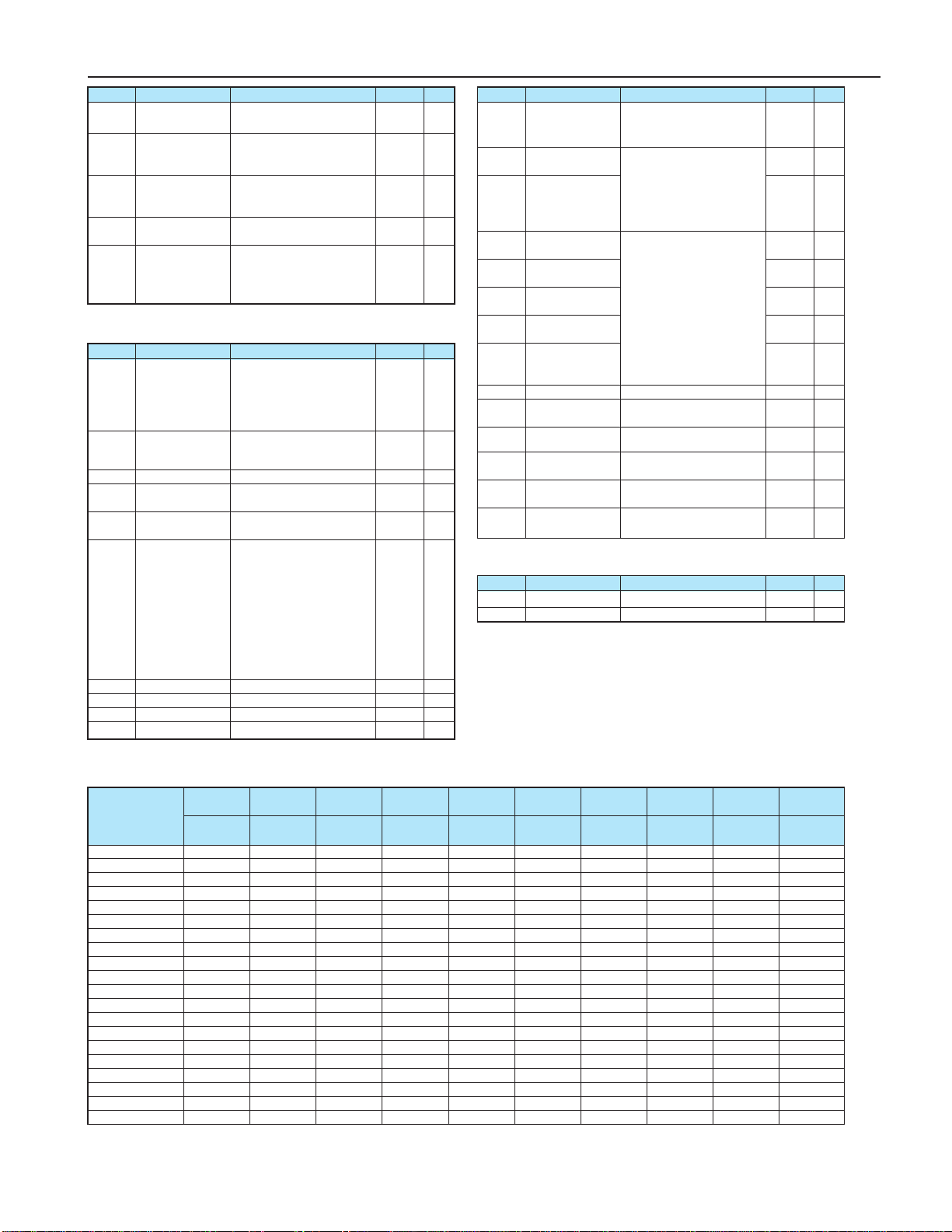
19
Table of Parameters
F730 0
F733 0
F734 0
F735 0
F736 1
●Communication Parameters
F800 3
F801 1
F802 0
F803 0
F805 0.00
F806 0
F811 0
F812 0.0
F813 100
F814 60.0
F829 0
F870 0
F871 0
F875 0
F876 0
F877 0
F878 0
F879 0
F880 0
F890 0
F891 0
F892 0
F893 0
F894 0
●Unused Parameter
F910 100
F911 0.0
*1: Default setting of the parameter differs by each inverter capacity. Refer to
"Default settings by Inverter Rating" table below for actual values.
*2: Unit displayed may be selected by parameter F701 (Unit selection).
*3: Always implement DC reactor (optional) when setting parameter F627
(Undervoltage trip/alarm selection) to "2(detection level below 50%)."
Title Function Adjustment range
Default setting
Note
Panel operation
prohibition (FC)
Prohibition of panel
operation
(RUN/STOP keys)
Prohibition of panel
emergency stop
operation
Prohibition of panel
reset operation
Prohibition of
change of
CMod/FMod during
operation
0: Permitted,
1: Prohibited
0: Permitted,
1: Prohibited
0: Permitted,
1: Prohibited
0: Permitted,
1: Prohibited
0: Permitted,
1: Prohibited
Communication
band speed
Parity (Common serial)
Inverter number
Communication
error trip time
Communication
waiting time
Setting of master
and slave inverters
for communications
between inverters
Point # 1 setting
Point # 1 frequency
Point # 2 setting
Point # 2 frequency
0: 1200bps
1: 2400bps
2: 4800bps
3: 9600bps
4: 19200bps
0: NON (No parity)
1: EVEN (Even parity)
2: ODD (Odd parity)
0-255
0: Disabled (*)
1-100 (s)
0.00-2.00 (s)
0:
Slave inverter (0 Hz command issued in
case the master inverter fails)
1:
Slave inverter (Operation continued
in case the master inverter fails)
2:
Slave inverter (Emergency stop tripping
in case the master inverter fails)
3: Master inverter (transmission
of frequency commands)
4: Master inverter (transmission
of output frequency signals)
0-100 (%)
0-500.0 (Hz)
0-100 (%)
0-500.0 (Hz)
Title Function Adjustment range
Default setting
Note
Title Function Adjustment range
Default setting
Note
Selection of
communication
protocol
Block write data 1
Block write data 2
Block read data 1
Block read data 2
Block read data 3
Block read data 4
Block read data 5
Free notes
Parameters for
option 1
Parameters for
option 2
Parameters for
option 3
Parameters for
option 4
Parameters for
option 5
0: Sumitomo Inverter protocol
1: Modbus RTU protocol
0: No selection
1: Command information 1
2: Command information 2
3: Frequency command
4:
Output data on the terminal board
5:
Analog output for communications
0: No selection
1: Status information
2: Output frequency
3: Output current
4: Output voltage
5: Alarm information
6: PID feedback value
7: Input terminal board monitor
8:
Output terminal board monitor
9: VRF terminal board monitor
10:VRF2 terminal board monitor
0-65535
0-65535
0-65535
0-65535
0-65535
0-65535
Title Function Adjustment range
Default setting
Note
-
-Do not change
Do not change
ub/F172 F308 F309 F401 F402 F415 F416 F417 F494 F626
(%) (:) (kW) (%) (%) (A) (%) (r/min) (%)
●Default Settings by Inverter Rating
HF321S-A20 6.0 400.0 0.2 100 7.0 1.5 85 1750 90 134
HF321S-A40 6.0 200.0 0.2 80 6.4 2.3 84 1735 90 134
HF321S-A75 6.0 200.0 0.3 70 4.7 3.9 75 1740 80 134
HF321S-1A5 6.0 80.0 0.3 80 5.0 6.6 55 1720 70 134
HF321S-2A2 5.0 70.0 0.4 75 3.8 9.3 55 1745 70 134
HF3212-A20 6.0 400.0 0.2 100 7.0 1.5 85 1750 90 134
HF3212-A40 6.0 200.0 0.2 80 6.4 2.3 84 1735 90 134
HF3212-A75 6.0 200.0 0.3 70 4.7 3.9 75 1740 80 134
HF3212-1A5 6.0 80.0 0.3 80 5.0 6.6 55 1720 70 134
HF3212-2A2 5.0 70.0 0.4 75 3.8 9.3 55 1745 70 134
HF3212-3A7 5.0 40.0 0.6 80 3.6 14.8 44 1740 70 134
HF3212-5A5 4.0 20.0 1.5 75 3.8 21.5 42 1750 70 134
HF3212-7A5 3.0 20.0 1.5 75 4.0 29.1 43 1755 70 134
HF3214-A40 6.0 750.0 0.2 76 6.4 1.2 82 1735 90 140
HF3214-A75 6.0 750.0 0.3 70 4.2 1.9 75 1740 80 140
HF3214-1A5 6.0 400.0 0.3 80 5.4 3.3 55 1720 70 140
HF3214-2A2 5.0 250.0 0.4 75 3.5 4.7 55 1745 70 140
HF3214-3A7 5.0 160.0 0.6 85 3.2 7.4 44 1740 70 140
HF3214-5A5 4.0 83.0 1.2 65 3.9 10.7 42 1750 70 140
HF3214-7A5 3.0 83.0 1.2 75 3.6 14.6 43 1755 70 140
Inverter type
Torque
boost
Dynamic braking
resistance
Dynamic braking
resistor capacity
Slip frequency
gain
Motor constant #1
(primary resistance)
Motor rated
current
Motor no-load
current
Motor rated
speed
Motor adjustment
factor Over-voltage stall
protection level
TD-20
LCI FURNACES - TPSI
This manual suits for next models
10
Table of contents
Popular Inverter manuals by other brands


Fuji Electric
Fuji Electric FRENIC-Lift series instruction manual

Uniteck
Uniteck UNIPOWER 800.12 PRO instruction manual

SMA
SMA SUNNY TRIPOWER CORE1 operating manual

meibes
meibes Solar Station XL Technical information for installation and operation

Growatt
Growatt SPF 3500 ES user manual

Chint Power
Chint Power CPS SC2.8KTL Installation and operation manual