LDG RBA-1 User manual

LDG RBA-1 4:1 Balun
LDG RBA-1:1 1:1 Balun
Table of Contents
Introduction 2
Features 2
Specifications 2
Preparation 3
An important word about power levels: 3
Installation 4
Care and Maintenance 9
Technical Support 9
Warranty and Service 9
Feedback Error! Bookmark not defined.
1445 Parran Road, PO Box 48
St. Leonard, MD 20685
Tech Support: 410-586-2177
Toll Free Order: 1-877-890-3003
24 Hour FAX: 410-586-8475
www.ldgelectronics.com
1

Introduction
Congratulations on selecting the LDG balun. Your LDG balun allows you to connect longwires
and antennas fed with ladder line to your LDG tuner. Two versions are available: the RBA-1
provides a 4:1 impedance transformation, while the RBA-1:1 has 52 ohm input and output.
LDG pioneered the automatic, wide-range switched-L tuner in 1995. From its laboratories near
our nation’s capitol, LDG continues to define the state of the art in this field with innovative
automatic tuners and related products for every amateur need. The RBA-1 and RBA-1:1 are
valuable accessories for any LDG tuner, extending its usefulness to virtually all types of antennas
and transmission lines in amateur use.
Features
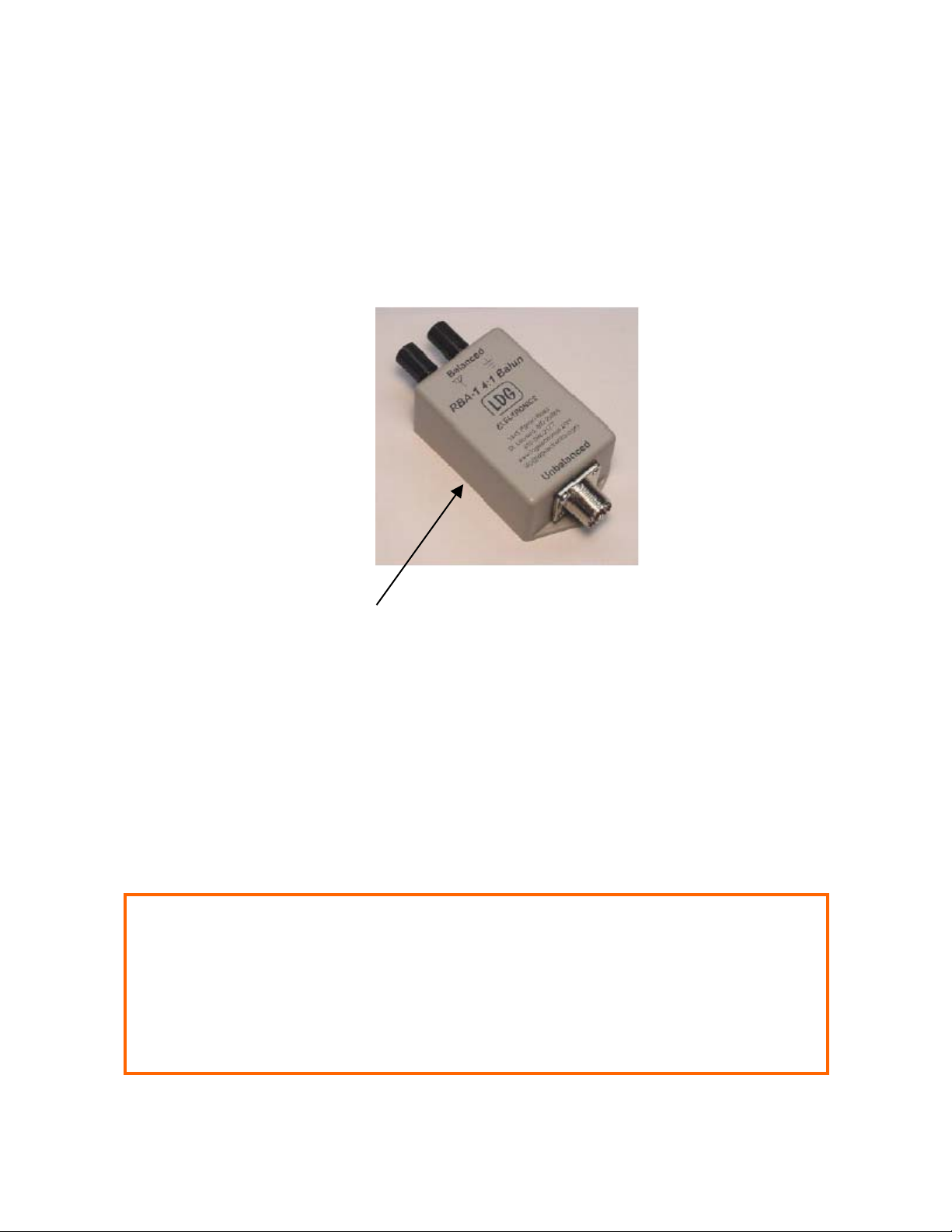
• Compact, sturdy construction
• Standard SO-239 jack for coax input
• Twist-on binding posts for ladder line, longwire or random wire attachment
• Can be waterproofed for outdoor use
• Broadband operation; covers the entire HF spectrum from 1.8 – 30 MHz
• Handles up to 200 watts continuously
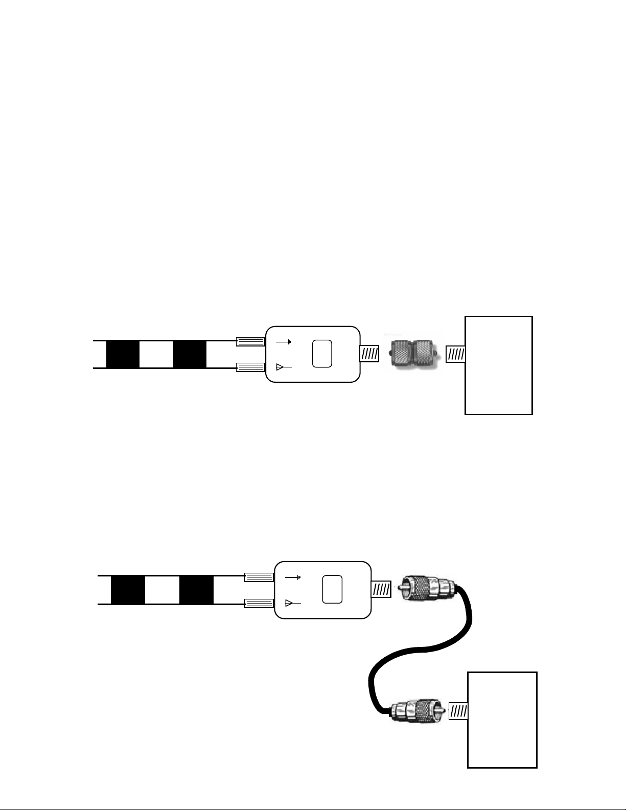
Your LDG balun performs two important functions:
1. It provides a convenient connection interface between coaxial cable and either ladder line or a
longwire antenna
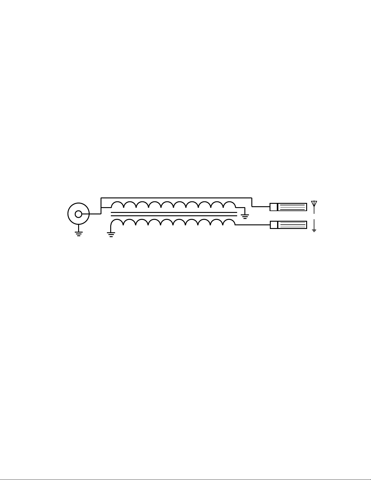
2. It converts from an unbalanced source (e.g., a transmitter or tuner with coaxial output) to a
balanced transmission line (e.g., ladder line)
In addition, the RBA-1 provides a 4:1 impedance conversion permitting use of higher impedance
antennas and transmission lines.
Specifications
• Weight: 6 oz (with enclosure)
• Frequency Coverage: 1.8 to 30 MHz
• Power Range: to 200 watts
• Easy to weatherproof
• Size overall: 5 x 2.5 x 1.25 inches
• Impedance transformation 1:1 or 4:1
2

Preparation
As it comes from the factory your LDG balun is water resistant. There are neoprene seals under the
SO-239 coax socket and the two binding posts. If the balun is mounted with the removable lid
(back) facing down (that is, with the writing facing up), it is reasonably water resistant. You can
make it completely waterproof and suitable for direct exposure to the weather at any mounting
angle for outdoor use if you wish. Simply apply a bead of Silicone caulking material (available at
any hardware store) around the back plate seal, and let it dry before use.
Waterproof here
An important word about power levels:
Your LDG balun is rated at 200 watts continuous power input at most. Some ham transmitters and
transceivers, and virtually all amplifiers, output well over 200 watts. Power levels significantly
exceeding specifications will definitely damage or destroy your LDG balun. If the balun fails under
extreme overload, your transmitter and tuner could also be damaged. Be sure to observe the
specified power limitations.
IMPORTANT SAFETY WARNING
Never install antennas over or near power lines. You can be seriously
injured or killed if any part of the antenna touches the power line.
Always follow this antenna safety rule: the distance to the nearest power
line should be at least twice the length of the longest antenna dimension.
3

Installation
You will install your LDG balun between your tuner (or transmitter/transceiver if you are not
using a tuner) and your antenna. You can attach it directly to the SO-239 output jack of your
tuner or transmitter/transceiver, or you can install it remotely at the end of any length of 52 ohm
coaxial cable.
Direct connection:
You can mount your LDG balun directly to the output jack of your tuner using a male-male PL-
259 adapter (not supplied). Simply attach the adapter to the balun, then attach the balun to the
output jack. Make sure the balun has adequate mechanical support, so it does not place excessive
torque on the antenna jack of your tuner or radio.
This type of connection is only recommended if the tuner is mounted remotely or the operating
position is outdoors. The use of ladder line indoors can sometimes lead to RFI issues near the
operating position. Whenever possible, use the remote connection as shown below.
RBA-1 4:1 Balun
Balanced
Unbalanced
LDG
Electronics
Tuner
Antenna
Ladder Line to antenna
Remote connection:
You can mount your LDG balun remotely, connecting it to your tuner with any length of 52 ohm
coaxial cable of suitable power handling capacity (typically RG-58, or some version of RG-8).
Properly soldered PL-259 connectors will be far more satisfactory than crimp-on or “solderless”
connectors. If you mount your balun outdoors and exposed to direct weather, LDG recommends
that you waterproof it as described above.
4
RBA-1 4:1 Balun
Balanced
Unbalanced
LDG
Electronics
Tuner
Antenna
Ladder Line to antenna
52 Ohm Coax
(any length)

A note about ladder line: unlike coax, ladder line performance can be strongly influenced by
conductive elements nearby, such as aluminum house siding, gutters, other wires or the earth.
You must take care to route your ladder line correctly, using standoffs and insulators as needed.
To avoid a degradation of performance, mount your balun remotely and use coaxial cable to
connect to the tuner or radio.
Longwire and Random antennas:
Longwire and Random antennas are typically elevated wires at least one wavelength long at the
lowest frequency to be used. As a general rule, the higher the better, and the longer the better.
Longwire antennas are somewhat directional; the main lobe is along the direction of the wire.
Performance of any longwire antenna will depend in large part on the quality of the ground
connection.
If the Longwire or Random wire is less that one wavelength, then it is typically referred to as a
short wire antenna. For short wire antennas, use a 1:1 balun for best performance.
Any Longwire or Random wire must be connected to ground or a counterpoise wire for best
results.
RBA-1 4:1 Balun
Balanced
Unbalanced
LDG
Electronics
To
tuner
Longwire antenna (generally
one wavelength or longer)
Ground wire (as
short as possible)
Antenna support
(tower, post, tree, etc)
Buried ground
system
(Not to scale)
LDG strongly recommends that you use a high-quality, properly
installed lightning arrestor in all your antenna feed lines.
5

Theory of operation:
Virtually all amateur transmitters and transceivers in use today, and all LDG tuners, are designed
with an unbalanced output. This means that the output signal appears on a single conductor
referenced to a grounded second conductor. Most amateur transmitters use a “pi network” output,
and LDG tuners employ a “switched-L” network, both of which feature an unbalance output.
These output sections are designed to be used with coaxial cable, an unbalanced transmission
line. The signal is carried on the center conductor, and the reference ground is the inside surface
of the shield1; the two signals are equal in amplitude but 180 degrees out of phase. These two out-
of-phase signals cancel each other out along the length of the coax, preventing it from radiating,
and delivering almost all of the RF energy to the antenna feedpoint.
Many commonly used amateur antennas are balanced antennas; examples include a dipole, and
the driven element of a Yagi-Uda array (a “Yagi” antenna). A balanced antenna features two
equal electrical elements driven 180 degrees out of phase. It is common amateur practice to feed
such antennas directly with coaxial cable, an unbalanced transmission line. At the interface
between the unbalanced transmission line and the balanced antenna, an extraneous current flow is
created on the outside of the coax shield. This is called a “common-mode” current, as it is in the
same direction as the signal on the center conductor.
~
Transmitter
Coax
1/2 wavelength dipole
Center conductor current
Inside shield current Outside “common-mode”
shield current due to
balanced-to-unbalanced
transition
6
1The so-called “skin effect” confines RF currents to the surface of conductors.

This common-mode current has three disadvantages. First, it radiates a signal that can distort the
radiation pattern of the antenna. For example, the symmetrical “figure eight” pattern of a dipole
can be distorted into a highly asymmetric blob who’s performance is difficult or impossible to
predict. Second, this radiation subtracts from the useful RF energy radiated to the receiving
station. Third, the RF on the outside of the shield can be conducted back into the transmitter,
causing problems such as distorted transmit audio.
Normal dipole
“figure eight”
radiation pattern
Distorted radiation
pattern due to
common-mode
coax radiation
0
90
180
270
0
90
180
270
The term “balun” stands for “balanced-unbalanced”. A balun is a matching transformer designed
to interface between unbalanced transmission lines and balanced antennas, or between the
unbalanced output section of a transmitter or tuner and a balanced transmission line. Some baluns
also act as an impedance matching transformer, converting the lower impedance of the transmitter
to the higher impedance of certain transmission lines. In principal, you should use a balun at the
feedpoint of a dipole where the coax is attached. However, in practice, the diameter of the coax is
usually such a small fraction of the feedline length that the effects can be largely ignored2.
A more significant problem is using ladder line to feed a high-impedance antenna such as a
folded dipole or loop. Ladder line has several advantages over coax that recommend it in some
applications. However, the transition from the unbalanced output section of the transmitter or
tuner to the balanced transmission line can create significant problems. A balun must be used in
this case, both to make the unbalanced-to-balanced transition, and also to match the higher
impedance if needed.
7
2It is common to address this problem by making a choke at the feedpoint by coiling the coax.

There are two general classes of balun: voltage and current. Voltage baluns place an inductance
across the load, and present an equal RF voltage on both sides of the balanced output. This
creates a balanced RF current in each side of the load in the degree that they are electrically
equal. Current baluns do not place an inductance across the load, and present an equal current in
each side of the balanced output over a somewhat wider range of conditions. Current baluns also
have a somewhat wider bandwidth. The LDG RBA-1:1 is a current balun, while the RBA-1 is a
voltage balun.
Your LDG balun consists of two bi-filar windings of heavy insulated wire on a toroid core of
high-permeability ferrite. These windings form a low-loss transformer that performs the
balanced-to-unbalanced conversion, and in the case of the RBA-1, acts as a 4:1 impedance
matching transformer as well.
Bifilar turns #18 insulated
wire on FT-125 toroid coil
SO-239 coax
connector
Balanced Unbalanced
Binding post
connectors
RBA-1
8

Care and Maintenance
Your LDG balun is essentially maintenance-free; just be sure to observe the power limits
discussed in this manual. Avoid getting the balun wet, unless you have waterproofed it as
discussed above. The outer case may be cleaned as needed with a soft cloth slightly dampened in
household cleaning solution. LDG strongly recommends that you use a good quality, properly
installed lightning arrestor in the antenna lead.
Technical Support
We are happy to help you with your LDG balun. Telephone technical support is available at 410-
586-2177 weekdays from 9 am to 5 pm Eastern Time. Inquiries by Fax at 410-586-8475 are
Warranty and Service
Your LDG balun is warranted against defects in parts or workmanship for one year from
purchase. The warranty does not cover damage due to abuse or exceeding specifications. This
warranty applies to the original purchaser only; it is not transferable. A copy of the receipt
showing the purchaser’s name and the date of purchase must accompany units returned for
warranty service. All returns must be shipped to us pre-paid; we will not accept units with
postage due. A return form is provided on our web site for your convenience.
If you need to return your LDG balun to us for service, package it carefully, keeping in mind that
we will re-use your packaging to return the unit to you. A self-addressed return-shipping label,
while not required, will help insure speedy and accurate delivery of your repaired unit. Include a
full description of the problem, along with your name, address and a phone number or e-mail
address where we can reach you with any questions. Repairs average about 2 to 4 weeks.
We will be glad to service your balun after the warranty period has ended. We will notify you of
repair charges by phone or e-mail, and bill you after repairs are completed.
9
This manual suits for next models
1
Table of contents