LEAB BW 801e User manual
www.leab.eu
USER MANUAL
VERSION 1
14/04/2021
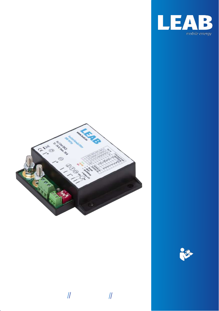
BATTERY WATCH
BW 801E
LEAB Automotive GmbH Thorshammer 6 24866 Busdorf
Table of Contents
1 About this Manual................................................................................................................ 3
2 General Safety........................................................................................................................ 4
2.1 Intended Use............................................................................................................... 5
3 Package Contents................................................................................................................. 6
4 Technical Specifications.................................................................................................... 7
5 About this Product............................................................................................................... 8
6 Setting the Threshold Values (DIP Switches)............................................................ 9
7 Installation.............................................................................................................................. 9
7.1 Optional: connect external buzzer..................................................................... 10
7.2 Optional: Using the battery monitor as a main switch............................. 10
7.3 Optional: Connect a 3-colour LED...................................................................... 11
8 Operating status................................................................................................................... 11
9 Decommissioning................................................................................................................. 12
10 Disposal.................................................................................................................................... 12
11 EU Declaration of Conformity.......................................................................................... 13
LEAB Automotive GmbH
1 About this Manual
Read this manual carefully and keep it in a safe place. This manual is aimed at
Skilled workers in the field of automotive electrics
Any modifications to the product or its components are prohibited and do not
conform to its intended use. Only use original LEAB or LEAB-approved ac-
cessories.
Throughout the manual, you will be alerted to warnings and safety notices
about potential hazards associated with handling the device. The colours and
signal words indicate the severity of the hazard:
Notice
Possibility of material damage
The signal word
Attention
indicates that there is a possibility of
material damage. To avoid material damage, follow the
instruction.
CAUTION
Danger that can lead to minor injuries
A safety instruction with the signal word
CAUTION
denotes a
hazard with a low degree of risk which, if not avoided, can result
in minor or moderate injury. Read the safety information carefully
and follow the instructions to avoid it.
WARNING
Hazards that can lead to severe injuries or death
A safety instruction with the signal word
WARNING
indicates a
hazard with a high degree of risk which, if not avoided, will result
in death or severe injury. Read the safety information carefully
and follow the instructions to avoid it.
3LEAB Automotive GmbH Thorshammer 6 24866 Busdorf
LEAB Automotive GmbH

DANGER
Danger that will lead to severe injury or death
A safety instruction with the signal word
Danger
indicates a
hazard with a high degree of risk which, if not avoided, will result
in death or severe injury. Read the safety information carefully
and follow the instructions to avoid it.
You will find notes at some points in the manual. These appear as follows:
NOTE
A note provides useful tips and information about the product.
Read the note carefully and follow the instructions where
applicable.
2 General Safety
This manual will help you to handle the device safely. Use the device solely in
accordance with its intended use. Observe the safety instructions.
WARNING
Fire hazard
Incorrect installation or inadequate wiring can result in a build-up
of heat.
1. Only install the device as described in this guide.
2. Select a sufficient cable cross-section to connect the device.
4 LEAB Automotive GmbH Thorshammer 6 24866 Busdorf
LEAB Automotive GmbH
WARNING
Risk of injury from electric shock
Short circuit currents can result in electric shock.
1. Disconnect the battery negative lead prior to assembly/disas-
sembly
Notice
Incorrect installation can damage the device
Using the device outside the specified operating parameters may
damage the device.
1. Before assembling and installing the device, make sure that it
is suitable for your use.
Notice
Device defects from incorrect installation
Incorrect installation can result in device defects.
1. Install the device in a dry and cool location.
Notice
Damage due to residual voltage
Residual voltage in the vehicle power circuit can cause damage to
the vehicle electronics.
1. Do not place the positive lead on the vehicle bodywork.
2.1 Intended Use
Use the BW 801e battery monitor to protect your battery against deep dis-
charge. The device prevents the battery voltage from falling below a set level.
Use the device for batteries with a nominal voltage of 12 V or 24 V.
5LEAB Automotive GmbH Thorshammer 6 24866 Busdorf
LEAB Automotive GmbH
3 Package Contents
No. Name
1x BW801e battery monitor
2x Insulating cap (400N9V02)
1x 3-colour LED
Accessories
Part number Name
1401036701 3-colour LED in socket with cable (5m)
1401036702 3-colour LED in socket with cable (1m)
6 LEAB Automotive GmbH Thorshammer 6 24866 Busdorf
LEAB Automotive GmbH

4 Technical Specifications
Part no.: 1305041043
Modell BW 801e
Nominal voltage (DC) 12 V or 24 V
Continuous load 50 A
Overload (10 s) 70 A
Switch-off voltage 12 V: 9 V … 12 V; 24 V: 18 V … 24 V (ad-
justable)
Betriebstemperatur -30 °C … +70 °C
Internal consumption 6 mA
Dimensions (L x W x H) 100 mm x 90 mm x 25 mm
Weight 0.11 kg
7LEAB Automotive GmbH Thorshammer 6 24866 Busdorf
LEAB Automotive GmbH

5 About this Product
The BW 801e battery monitor is a two-stage safety system to avoid deep dis-
charge of your battery. Audible and visual alarms warn you of an approaching
deep discharge. If power continues to be removed from the battery, the bat-
tery monitor disconnects consumers from the battery to prevent deep dis-
charge. The threshold values for the alarm and for switching off the con-
sumers are set via DIP switches.
1
2
34 5 6 7 8
9
10
Fig.1:
BW 801e
1 Consumer connector 2 Battery connector
3 Operating display 4 “External switch” connector
5 “Alarm output” connector 6 “Ground” connector
7 “Green” LED connector (+) 8 LED connector (-)
9 “Red” LED connector (+) 10 DIP switch
8 LEAB Automotive GmbH Thorshammer 6 24866 Busdorf
LEAB Automotive GmbH
6 Setting the Threshold Values (DIP Switches)
DIP ON Switch-off
voltage [V] Alarm threshold
[V] Switch-on
voltage [V]
1 2 3 4 12 V 24 V 12 V 24 V 12 V 24 V
0 0 0 - 9 18 9.5 19 10.5 21
1 0 0 - 9.5 19 10 20 11 22
0 1 0 - 10 20 10.5 21 11.5 23
1 1 0 - 10.5 21 11 22 12 24
0 0 1 - 11 22 11.5 23 12.5 25
1 0 1 - 11.5 23 12 24 13 26
0 1 1 - 12 24 12.5 25 13.5 27
1 1 1 - - - - - - -
- - - 0 Internal buzzer on
- - - 1 Internal buzzer off
7 Installation
Observe the following notes when installing the device:
WARNING
Risk of injury from electric shock
Short circuit currents can result in electric shock.
1. Disconnect the battery negative lead prior to assembly/disas-
sembly
Notice
Damage due to residual voltage
Residual voltage in the vehicle power circuit can cause damage to
the vehicle electronics.
1. Do not place the positive lead on the vehicle bodywork.
9LEAB Automotive GmbH Thorshammer 6 24866 Busdorf
LEAB Automotive GmbH

To install the device, proceed as follows:
1 Disconnect the battery from the vehicle power circuit.
WARNING!Disconnect the negative cable first.
Fig.2: DIP switch
2 Set the desired switch-off voltage on the DIP switches
(10).
3 Connect an earth wire from the battery monitor’s
ground (6) terminal to the battery's negative terminal.
NOTE!Only the switching current (1 A) is permissible.
The consumer load must not lead via the 'ground’ con-
nector (6).
4 Disconnect the positive lead from the battery to the
consumers and connect the battery monitor at the
screw terminals (1) and (2).
5 Connect the battery to the vehicle power circuit.
ðThe device is ready for operation. When the battery
voltage is sufficient, the operating display (3) lights
green.
7.1 Optional: connect external buzzer
To connect an external buzzer, proceed as follows:
NOTE!Contact to ground, max. 1 A.
1 Connect an external buzzer via the ‘alarm output’ connector (5).
ðAn external buzzer is connected.
7.2 Optional: Using the battery monitor as a main switch
To use the battery monitor as a main switch for the connected consumers,
proceed as follows:
1 Lay a cable with a switch between the negative terminal of the battery and
the connector for the external switch (4).
ðThe battery monitor is used as the main switch.
10 LEAB Automotive GmbH Thorshammer 6 24866 Busdorf
LEAB Automotive GmbH
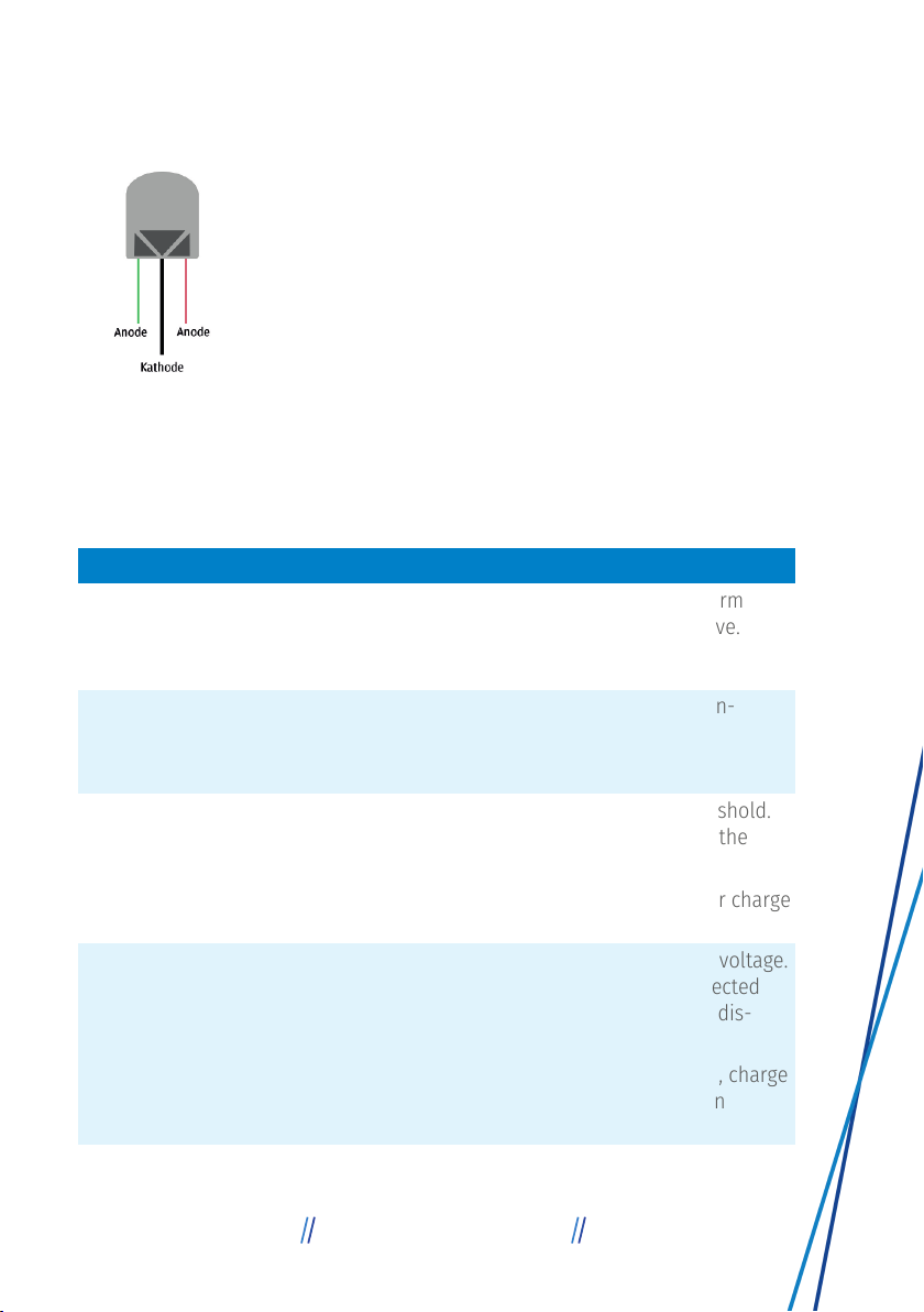
7.3 Optional: Connect a 3-colour LED
Fig.3: 3-colour LED
To connect the 3-colour LED, proceed as follows:
1 Connect the anode for green (shortest leg) to the con-
nector (7).
2 Connect the cathode (longest leg) to the connector (8).
3 Connect the anode for red to the connector (9).
ðThe 3-colour LED is connected.
8 Operating status
The operating status of the unit is indicated by the operating display (3), the
3-colour LED, the alarm output (5) and the internal buzzer.
Indicator Status
LED lit green
Alarm output inactive
Internal buzzer off
Battery voltage is above the alarm
threshold setting, device is active.
LED flashes green
Alarm output inactive
Internal buzzer off
External switch (4) is closed, con-
sumers are switched off.
LED lit orange
Alarm output active
Internal buzzer beeps at interval*
Safety level 1: Below alarm threshold.
Battery voltage will soon reach the
switch-off voltage.
1 Switch the consumers off or charge
the battery
LED flashes red
Alarm output inactive
Internal buzzer beeps 1x
Safety level 2: Below switch-off voltage.
Consumers have been disconnected
from the battery to avoid deep dis-
charge.
2 To supply consumers again, charge
the battery to the switch-on
voltage.
11LEAB Automotive GmbH Thorshammer 6 24866 Busdorf
LEAB Automotive GmbH

Indicator Status
LED no colour Device is switched off or incorrectly in-
stalled.
* Internal buzzer interval (in seconds): 600 – 300 – 150 – 75 – 37 – 18 – 9.
After that: Internal buzzer beeps every 9 seconds until the switch-off voltage is
reached.
9 Decommissioning
WARNING
Risk of injury from electric shock
Short circuit currents can result in electric shock.
1. Disconnect the battery negative lead prior to assembly/disas-
sembly
To decommission the device, proceed as follows:
1 Disconnect the battery from the vehicle power circuit.
WARNING!Disconnect the negative cable first.
2 Remove the leads on the connectors (1), (2), (4), (5) and (6) from the vehicle.
3 Remove the device from the vehicle.
ðThe device is decommissioned.
10 Disposal
Dispose of the device in accordance with the Waste Elec-
trical and Electronic Equipment Regulations (WEEE).
The system must not be disposed of with household
waste. Take it to a recycling point or return it to your
point of sale.
12 LEAB Automotive GmbH Thorshammer 6 24866 Busdorf
LEAB Automotive GmbH

11 EU Declaration of Conformity
The BW 801e complies with the requirements of the fol-
lowing directives:
– 2014/30/EU: EMV
– 2011/65/EU: RoHS
13LEAB Automotive GmbH Thorshammer 6 24866 Busdorf
LEAB Automotive GmbH

14 LEAB Automotive GmbH Thorshammer 6 24866 Busdorf
LEAB Automotive GmbH

15LEAB Automotive GmbH Thorshammer 6 24866 Busdorf
LEAB Automotive GmbH

LEAB Automotive GmbH
Thorshammer 6
DE-24866 Busdorf
Tel: +49 (0) 4621 9 78 60-0
Fax: +49 (0) 4621 9 78 60-260
We make energy
mobile.
It is prohibited to copy, duplicate, translate or otherwise pass on the content of
this guide to third parties without the express written permission of LEAB.
Other manuals for BW 801e
3
This manual suits for next models
1
Table of contents
Other LEAB Watch manuals


