manuals.online logo
Brands
  1. Home
  2. •
  3. Brands
  4. •
  5. LEAB
  6. •
  7. Watch
  8. •
  9. LEAB BW 801e User manual

LEAB BW 801e User manual

Battery Watch
BW 801e
Quick start guide
V 2
General Safety
This guide supports safe handling of the product. Use the product
only in accordance with its intended use:
The BW 801e battery monitor is a two-stage safety system for pre-
venting deep discharge for batteries with a nominal voltage of 12 V
or 24 V.
Audible and visual alarms warn you of an approaching deep dis-
charge. If power continues to be removed from the battery, the bat-
tery monitor disconnects consumers from the battery to prevent
deep discharge. The threshold values for the alarm and for switch-
ing off the consumers are set via DIP switches.
Any modifications to the product or its components are prohibited
and do not conform to its intended use. Only use original LEAB or
LEAB-approved accessories.
Observe the safety instructions:
WARNING!Incorrect assembly or inadequate wiring can cause
a fire: Only install the unit as described in these instructions and se-
lect a sufficient cable cross-section for connecting the device.
WARNING!Risk of injury from electric shock: Disconnect the
battery negative lead prior to assembly/disassembly.
NOTE!Incorrect usage can damage the device: Only use the
device within the specified operating parameters.
NOTE!Install the device in a dry and cool location.
NOTE!Residual voltage can cause damage: Do not place the pos-
itive lead on the vehicle bodywork.
Package Contents
No. Name
1x BW801e battery monitor
2x Insulating cap (400N9V02)
1x 3-colour LED
Accessories
Part number Name
1401036701 3-colour LED in socket with cable (5m)
1401036702 3-colour LED in socket with cable (1m)
Technical Specifications
Part no.: 1305041043
Modell BW 801e
Nominal voltage (DC) 12 V or 24 V
Continuous load 50 A
Overload (10 s) 70 A
Switch-off voltage 12 V: 9 V … 12 V;
24 V: 18 V … 24 V (adjustable)
Operating temperature -30 °C … +70 °C
Internal consumption 6 mA
Dimensions (L x W x H) 100 mm x 90 mm x 25 mm
Weight 0.11 kg
Setting the Threshold Values (DIP Switches)
DIP ON Switch-off
voltage [V]
Alarm
threshold [V]
Switch-on
voltage [V]
1 2 3 4 12 V 24 V 12 V 24 V 12 V 24 V
0 0 0 - 9 18 9.5 19 10.5 21
1 0 0 - 9.5 19 10 20 11 22
0 1 0 - 10 20 10.5 21 11.5 23
1 1 0 - 10.5 21 11 22 12 24
0 0 1 - 11 22 11.5 23 12.5 25
1 0 1 - 11.5 23 12 24 13 26
0 1 1 - 12 24 12.5 25 13.5 27
1 1 1 - - - - - - -
- - - 0 Internal buzzer on
- - - 1 Internal buzzer off
LEAB Automotive GmbH
Thorshammer 6
DE-24866 Busdorf
Tel: +49 (0) 4621 9 78 60-0
Fax: +49 (0) 4621 9 78 60-260
[email protected]
It is prohibited to copy, duplicate, translate or otherwise
pass on the content of this guide to third parties without the
express written permission of LEAB.
We make energy mobile.
Installation
1
2
34 5 6 7 8
9
10
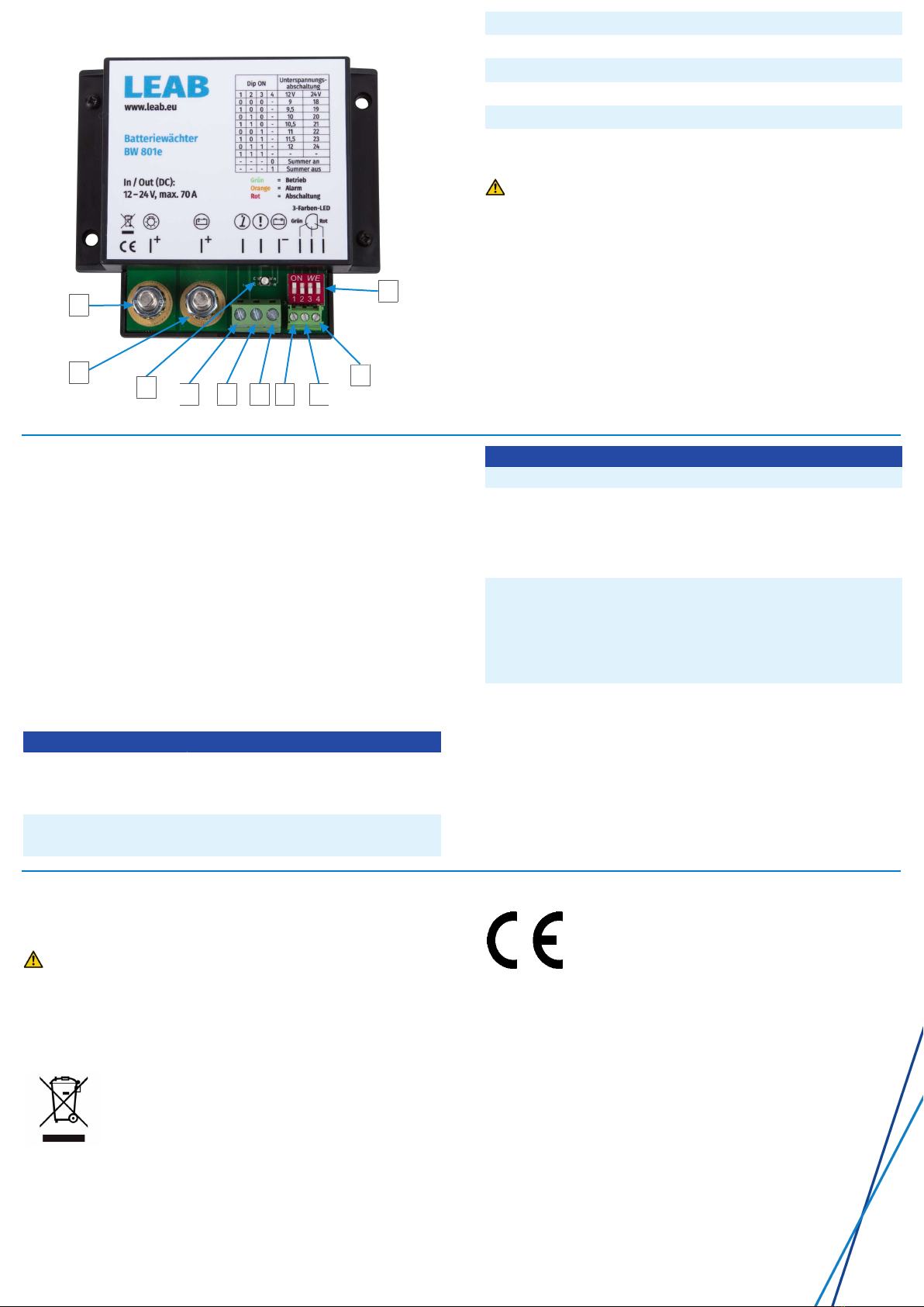
1Consumer connector 2Battery connector
3Operating display 4“External switch” connector
5“Alarm output” connector 6“Ground” connector
7“Green” LED connector (+) 8LED connector (-)
9“Red” LED connector (+) 10 DIP switch
To install the device, proceed as follows:
1. Disconnect the battery from the vehicle power circuit.
WARNING!Disconnect the negative cable first.
2. Set the desired switch-off voltage on the DIP switches (10).
3. Connect an earth wire from the battery monitor’s ground (6) con-
nector to the battery's negative terminal.
NOTE!Only the switching current (1 A) is permissible. The con-
sumer load must not lead via the 'ground’ connector (6).
4. Disconnect the positive lead from the battery to the consumers
and connect the battery monitor at the screw terminals (1) and
(2).
5. Connect the battery to the vehicle power circuit.
ðThe device is ready for operation. When the battery voltage is
sufficient, the operating display (3) lights green.
Optional connections
– Connect an external buzzer via the ‘alarm output’ connector
(5). NOTE!Contact to ground, max. 1 A.
– Use the battery monitor as a main switch for connected con-
sumers by running a line with a switch between the negative
terminal of the battery and the connector for “external
switch” (4).
– Connect the 3-colour LED by connecting the anode for green
(shortest leg) to the “Green” LED connector (7), the cathode
(longest leg) to the LED connector (8) and the anode for red to
the “Red” LED connector (9).
Operating status
Indicator Operating status
LED lit green
Alarm output inactive
Internal buzzer off
Battery voltage is above the alarm
threshold setting, device is active.
LED flashes green
Alarm output inactive
External switch (4) is closed, consumers
are switched off.
Indicator Operating status
Internal buzzer off
LED lit orange
Alarm output active
Internal buzzer beeps at
interval*
Safety level 1: Below alarm threshold.
Battery voltage will soon reach the
switch-off voltage.
1. Switch the consumers off or charge
the battery
LED flashes red
Alarm output inactive
Internal buzzer beeps 1x
Safety level 2: Below switch-off
voltage. Consumers have been discon-
nected from the battery to avoid deep
discharge.
2. To supply consumers again, charge
the battery to the switch-on voltage.
LED no colour Device is switched off or incorrectly in-
stalled.
* Internal buzzer interval: 600s – 300s – 150s – 75s – 37s – 18s
– 9s.
After that: Internal buzzer beeps every 9 seconds until the switch-
off voltage is reached.
NOTE!The operating status of the device is shown by the operat-
ing display (3), the 3-colour LED, the alarm output (5) and the in-
ternal buzzer.
Decommissioning
To decommission the device, proceed as follows:
1. Disconnect the battery from the vehicle power circuit.
WARNING!Disconnect the negative cable first.
2. Remove the leads on the connectors (1), (2), (4), (5) and (6)
from the vehicle.
ðThe device is decommissioned.
Disposal
Dispose of the device in accordance with the Waste
Electrical and Electronic Equipment Regulations
(WEEE).
The system must not be disposed of with household
waste. Take it to a recycling point or return it to your
point of sale.
EU Declaration of Conformity
The BW 801e complies with the requirements of the
following directives:
– 2014/30/EU: EMV
– 2011/65/EU: RoHS
LEAB Automotive GmbH // Thorshammer 6 // 24866 Busdorf

Other manuals for BW 801e

3

This manual suits for next models

1

Other LEAB Watch manuals

LEAB BW 801e User manual

LEAB

LEAB BW 801e User manual

LEAB BW 801e User manual

LEAB

LEAB BW 801e User manual

Popular Watch manuals by other brands

Coleman 40-908 user guide

Coleman

Coleman 40-908 user guide

ALZA WowME Roundswitch user manual

ALZA

ALZA WowME Roundswitch user manual

Casio 5102 Operation guide

Casio

Casio 5102 Operation guide

TFA 38.2030 operating instructions

TFA

TFA 38.2030 operating instructions

Seiko ASTRON 8X22 Complete user guide

Seiko

Seiko ASTRON 8X22 Complete user guide

Suunto CORE user guide

Suunto

Suunto CORE user guide

Casio 5623 user guide

Casio

Casio 5623 user guide

Timex W-91 manual

Timex

Timex W-91 manual

Oppo Watch user manual

Oppo

Oppo Watch user manual

Pro-4 Tactical Survival Watch instruction manual

Pro-4 Tactical

Pro-4 Tactical Survival Watch instruction manual

Casio 1301 user guide

Casio

Casio 1301 user guide

Seabear H3 user manual

Seabear

Seabear H3 user manual

Junghans J645.85 manual

Junghans

Junghans J645.85 manual

Casio 3526 Operation guide

Casio

Casio 3526 Operation guide

Samsung VERIZON GEAR S3 FRONTIER user guide

Samsung

Samsung VERIZON GEAR S3 FRONTIER user guide

ALIGATOR WATCH LADY user manual

ALIGATOR

ALIGATOR WATCH LADY user manual

SELLITA SW330-2 Technical documentation

SELLITA

SELLITA SW330-2 Technical documentation

Suunto AMBIT2 S 2.0 user guide

Suunto

Suunto AMBIT2 S 2.0 user guide

manuals.online logo
manuals.online logoBrands
  • About & Mission
  • Contact us
  • Privacy Policy
  • Terms and Conditions

Copyright 2025 Manuals.Online. All Rights Reserved.