Leader Evaporator Springtech MicRO User manual

Leader Evaporator Co., Inc.
49 Jonergin Drive
Swanton, VT 05488
Tel: 802-868-5444
www.leaderevaporator.com

Leader Evaporator Springtech MicRO Reverse Osmosis System Manual YEAR: 2017 Page: 2
TABLE OF CONTENTS
INTRODUCTION ..............................................................................................................................................................................4
THEORY OF OPERATION..................................................................................................................................................................4
Terms..............................................................................................................................................................................................4
Description of Membrane...............................................................................................................................................................5
EQUIPMENT DESCRIPTION..............................................................................................................................................................6
FRONT VIEW...........................................................................................................................................................................................6
REAR VIEW............................................................................................................................................................................................. 7
FEED PUMP ............................................................................................................................................................................................7
PRESSURE PUMP .....................................................................................................................................................................................8
PREFILTER ASSEMBLY ...............................................................................................................................................................................8
FRONT PANEL .........................................................................................................................................................................................8
MEMBRANE PRESSURE GAUGE AND CONTROL VALVE.....................................................................................................................................9
INCLUDED EQUIPMENT .............................................................................................................................................................................9
OPTIONAL SETUP EQUIPMENT,PARTS AND SUPPLIES...................................................................................................................................... 9
SETUP ...........................................................................................................................................................................................11
AREA REQUIRED ....................................................................................................................................................................................11
POWER REQUIREMENTS..........................................................................................................................................................................11
GENERAL CONNECTION LAYOUT ...............................................................................................................................................................11
Required Flows Diagram ..............................................................................................................................................................12
STRAINER CONNECTION ..........................................................................................................................................................................12
SYSTEM FLUID INPUT CONNECTION ...........................................................................................................................................................13
VESSEL AND PUMP DRAINS......................................................................................................................................................................13
CONCENTRATE AND PERMEATE OUTFLOW CONNECTIONS..............................................................................................................................14
Concentrate Flow Meter Connection............................................................................................................................................14
Permeate Flow Meter Connection................................................................................................................................................15
WASH TANK (TO BE SUPPLIED BY USER) ...................................................................................................................................................15
OPERATION ..................................................................................................................................................................................17
STARTING THE SYSTEM............................................................................................................................................................................17
RESET FOR LOW PRESSURE SHUTOFF.........................................................................................................................................................18
NORMAL SHUTDOWN............................................................................................................................................................................. 19
INITIAL SYSTEM CLEANING.......................................................................................................................................................................20
SAMPLING............................................................................................................................................................................................20
DATA LOGGING .....................................................................................................................................................................................20
CYCLES AND TIMING...............................................................................................................................................................................21
PERMEABILITY TEST................................................................................................................................................................................21
ADJUSTING V2 (FLOW VALVE)FOR OPERATIONS .........................................................................................................................................23
GENERALIZED SYSTEM SCHEMATIC ............................................................................................................................................................23
CONCENTRATE CYCLE .............................................................................................................................................................................25
DESUGAR CYCLE ....................................................................................................................................................................................27
RINSE CYCLE .........................................................................................................................................................................................28
WASH CYCLE ........................................................................................................................................................................................29
Hot Water Wash........................................................................................................................................................................... 29
Alkaline Soap Wash ......................................................................................................................................................................29
Acid Soak ...................................................................................................................................................................................... 29
MAINTENANCE .............................................................................................................................................................................31

Leader Evaporator Springtech MicRO Reverse Osmosis System Manual YEAR: 2017 Page: 3
PRE FILTERS.......................................................................................................................................................................................... 31
MEMBRANE REMOVAL AND INSTALLATION .................................................................................................................................................33
Removal........................................................................................................................................................................................ 33
Installation....................................................................................................................................................................................35
Replacement of Membrane Seal................................................................................................................................................................... 36
DAILY ..................................................................................................................................................................................................37
END OF SEASON SHUTDOWN AND STORAGE...............................................................................................................................................37
BEGINNING OF SEASON STARTUP..............................................................................................................................................................39
TROUBLESHOOTING CHART ..........................................................................................................................................................40
ATTACHMENT #1 –OPERATIONS DATA LOGSHEET .......................................................................................................................41
ATTACHMENT #2 –MEMBRANE PERMEABILITY TEST SHEET.........................................................................................................42
ATTACHMENT #3 –WARRANTY INFORMATION............................................................................................................................43

Leader Evaporator Springtech MicRO Reverse Osmosis System Manual YEAR: 2017 Page: 4
INTRODUCTION
A Leader Evaporator Springtech Reverse Osmosis system is designed to significantly improve the producer’s
productivity by generating higher sugar percentage sap. Through use of high pressure, the system removes water
from the sap resulting in a more concentrated sugar solution entering the evaporator. This in turn shortens the boil
time required and resulting in fuel and time savings. The Leader Evaporator MicRO is ideally suited for the small
producer seeking to gain the advantage of a large reverse osmosis system at an economical cost.
Some of the features of the Springtech MicRO are:
Easy accessibility to pumps and membranes
Stainless steel frame, membrane housings, pumps and pump housings
Flow meter for the permeate of the membrane and for the system concentrate
THEORY OF OPERATION
In reverse osmosis, through the use of special semi-permeable membranes and high pressure, water is forced, in a
pure form, through the membrane while the concentrated solution remains outside the membrane and is
concentrated. For the sugar maker this means water (permeate) is removed from the sap and a sap with a higher
sugar level (concentrate) is produced for the evaporation process.
Terms
Semi-permeable Membrane –Unit consisting of multi layers of spacers and membranes
Pre-Filter Unit –Designed to remove suspended solids from the sap incoming to the reverse osmosis
system
Feed Pump –The initial pump designed to supply the reverse osmosis unit with sap and maintain pressure
in the system
Pressure Pump –The pump designed to provide the pressure needed to force the sap through the reverse
osmosis membrane
Pressure Vessel –The containment unit for the semi-permeable membrane
Permeate –the water removed from the maple sap during the concentrate cycle
Concentrate –the maple sap having a higher percentage of sugar because water (permeate) has
been removed
Permeate Holding Tank –A tank designed to hold a minimum twice the hourly output of the system
Concentrate Cycle –Process during which water is removed from maple sap resulting in
Concentrate and Permeate
De-Sugaring Cycle - Process to reclaim sugars from the membrane during which Permeate is run
through the reverse osmosis unit using Concentrate cycle valve settings
Rinse Cycle –Cleaning process of passing stored Permeate through the Reverse Osmosis system and
out to drain
Chemical Wash Cycle –Process of chemical washing the membranes by recirculating a solution
through the reverse osmosis system. Dependent on requirement, chemical
maybe be alkali or acid.
Permeability Test –Test to determine the performance of the membranes against a benchmark
Sap Recirculation Loop –Process of recirculating output from the concentrate cycle to the raw sap
tank, increasing the concentration of the sap in the tank. NOTE: This loop
is not recommended for this system.

Leader Evaporator Springtech MicRO Reverse Osmosis System Manual YEAR: 2017 Page: 5
Description of Membrane
The drawing above represents the flow of liquid through a membrane in the system. The membrane is housed
in a pressure vessel (not shown).
Leader Evaporator Springtech MicRO Reverse Osmosis System Manual YEAR: 2017 Page: 6
EQUIPMENT DESCRIPTION
The LEADER EVAPORATOR Springtech Reverse Osmosis System is designed to offer maximum concentration to cost
performance. Through optimizing of pumps and membranes the reverse osmosis systems deliver greater flow
potential to the user. The LEADER EVAPORATOR Springtech Reverse Osmosis system is designed and built using the
same principles of superior quality applied to our evaporators.
The LEADER EVAPORATOR Springtech MicRO Reverse Osmosis System is covered by a manufacturer’s warranty – See
ATTACHMENT #3.
NOTES:
1. Pictures, sketches and drawings presented in this document are not to scale.
2. Directions (right and left) will be as facing the front of the system except where facing such parts as valves.
3. The pictures in this section are of a system with two membranes. A system with a single membrane is offered.
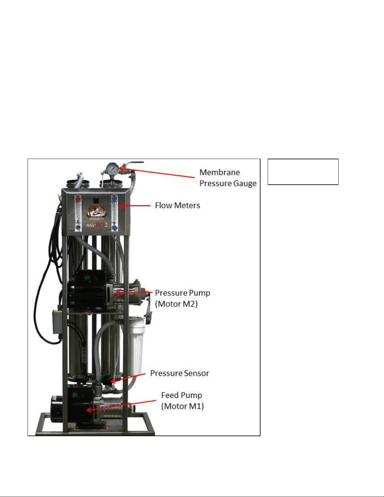
Front View

Leader Evaporator Springtech MicRO Reverse Osmosis System Manual YEAR: 2017 Page: 7
Rear View
Feed Pump
Provides liquid to the system and
is the first stage of pressurizing
the system

Leader Evaporator Springtech MicRO Reverse Osmosis System Manual YEAR: 2017 Page: 8
Pressure Pump
Second stage of pressurizing the
system required to process the
sap through the membranes
Prefilter Assembly
Prefilter assembly removes contaminants prior to
sap entering the membranes.
Prefilter assembly requires one 10” cartridge filter
Sap is pumped from the feed pump through the
prefilter then to the pressure pump.
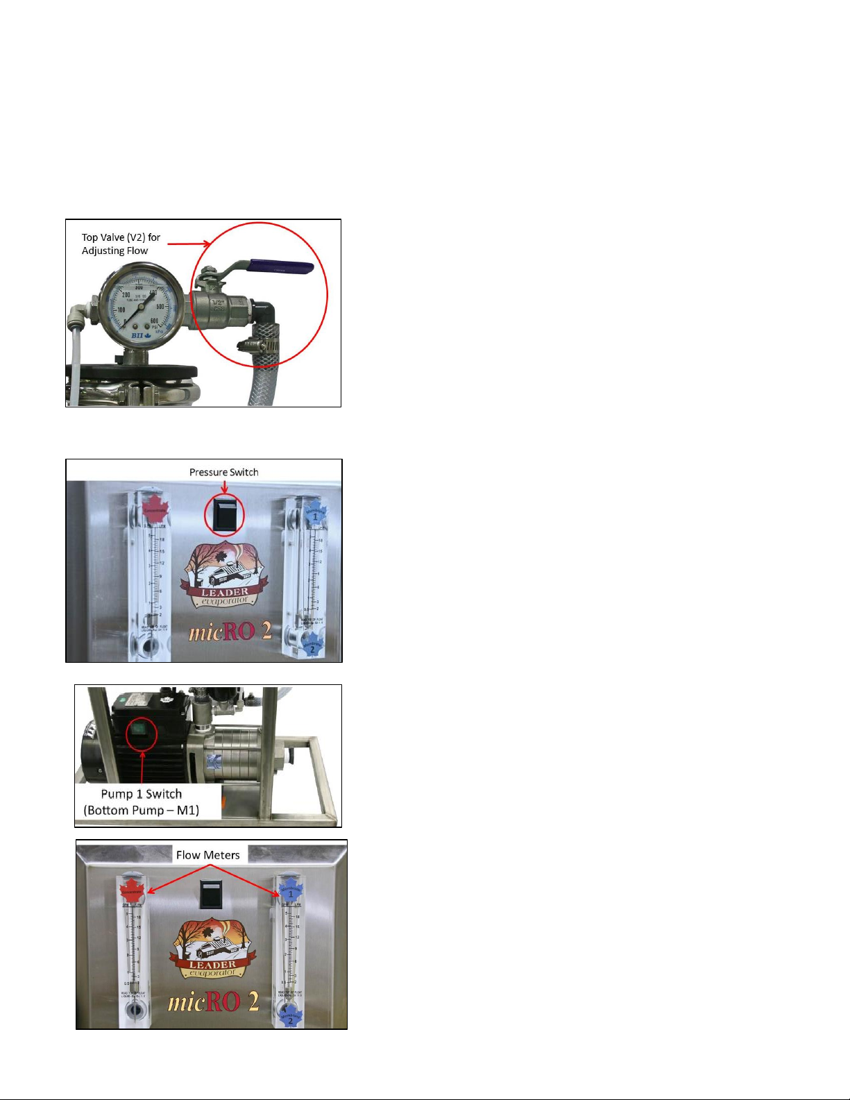
Front Panel
The Pressure Switch activates or deactivates the functioning
of the low pressure shutoff control of the system.
The Concentrate Flow Meter indicates the liquid flow, in
gallons per minute, from the concentrate side of the
pressure vessel(s).
The Permeate Flow Meter indicates the permeate flow, in
gallons per minute, from the membrane(s).
Leader Evaporator Springtech MicRO Reverse Osmosis System Manual YEAR: 2017 Page: 9
The Leader Springtech Reverse Osmosis system consists of the following parts:
Included Equipment
ITEM
LEADER
ORDER #
DESCRIPTION / PHOTO
ITEM
LEADER
ORDER #
DESCRIPTION / PHOTO
Springtech
MicRO
One
Membrane
Two
Membrane
70010
70012
Springtech
MicRO Quick
Start Guide
Springtech
MicRO User
Manual
Optional Setup Equipment, Parts and Supplies
ITEM
LEADER
ORDER #
DESCRIPTION / PHOTO
ITEM
LEADER
ORDER #
DESCRIPTION / PHOTO
1” Quick
Coupler C
Qty: 2
47148
1” Quick
Coupler F
47151
1” Stainless
Steel Band
Clamp
60043
1” PVC Ball
Valve
60130
1” Braided
Hose (by the
foot)
70285
TEFLON Tape
66106
½” PVC
Plastic to
Iron Adapter
½” Braided Hose
70297
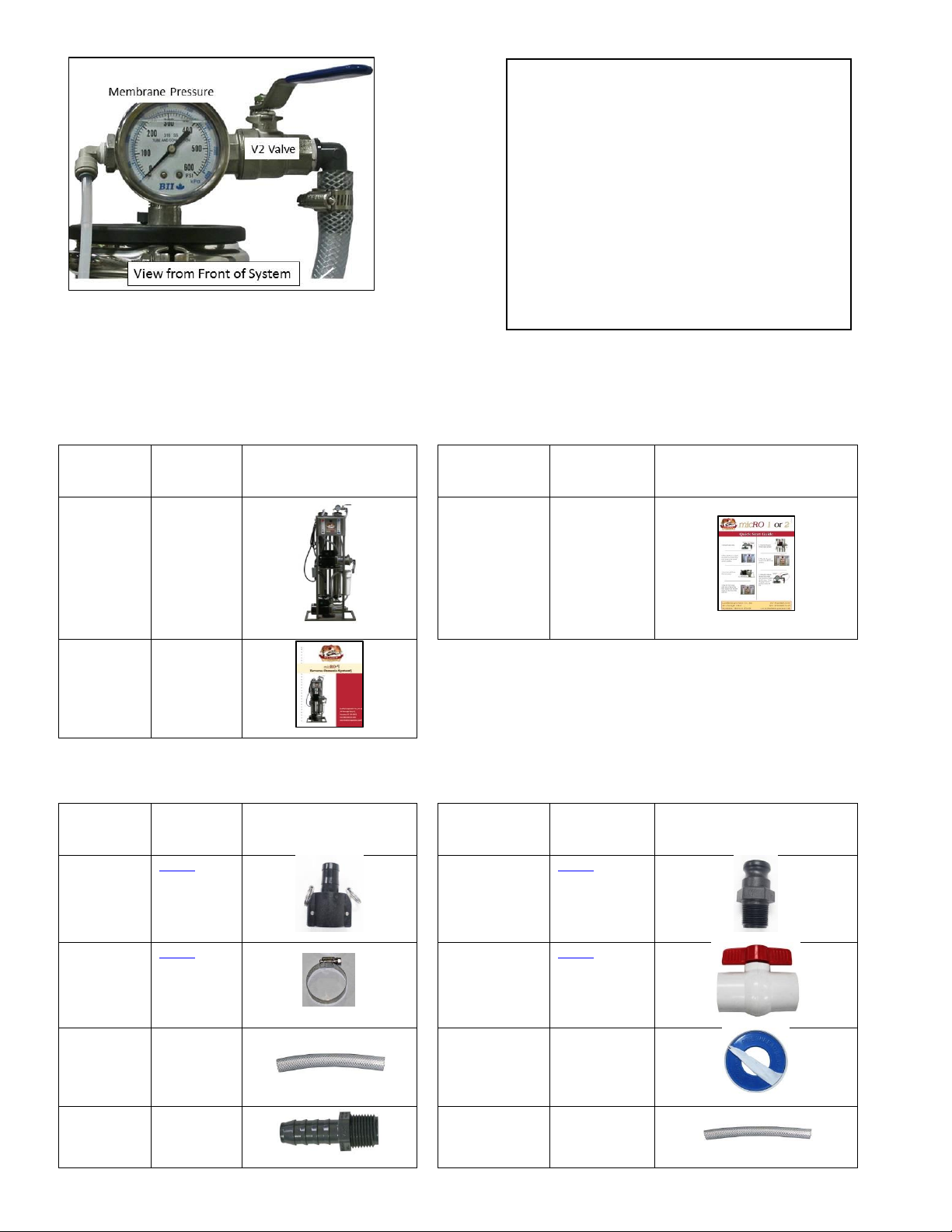
Membrane Pressure Gauge and
Control Valve
Membrane pressure is read after the last
membrane.
WARNING: DO NOT ALLOW THE PRESSURE
ON THE MEMBRANE(S) TO EXCEED 220 psi.
V2 controls the flow from the concentrate side of
the membranes. It is opened ½ way when starting
then adjusted to the desired concentration level.

Leader Evaporator Springtech MicRO Reverse Osmosis System Manual YEAR: 2017 Page: 10
½” Stainless
Steel Band
Clamp
60037
Digital
Thermometer
61005
Strainer Y
1” modified
with bleeder
valve
RO Soap 5 Lbs.
69992
Citric Acid, 1
lb.
70008
Glycol, 1 gal.
70009
Membrane
Preservative,
1 lb.
70001
10” Cartridge
Filter
70013
12” Sap
Hydrometer
61061
Long 2”
Diameter Test
Cup
59006
Digital
Refractomet
er
61058
Sap
Refractometer
61073
pH Meter
61060
pH Meter
Replacement
Probe
61060P
Food Grade
Grease
55095
Open Topped
Stock Tank –
150 Gallon –for
PERMEATE for
Single
Membrane RO
570150
Free
Standing Leg
Tank –325
gallon –for
Two
Membrane
RO
570325
MicRO Wheel
Kit
700005

Leader Evaporator Springtech MicRO Reverse Osmosis System Manual YEAR: 2017 Page: 11
SETUP
NOTES:
All materials used should be approved for potable water. No copper should be used.
When installing plumbing for the system, factor in the system may need to be moved for such items as
maintenance. It is recommended the connections be made with fittings such as quick disconnects.
All feed piping to the system must be at least as large as the feed on the system itself –1” is recommended
All installations must meet applicable governmental regulations.
Area Required
The space to be used should be capable of preventing the RO system from freezing. Additionally it will need to have
adequate ventilation during operations to prevent overheating.
The dimensions of the unit are
Width –14”
Length –24”
Height –57”
A minimum of two feet around the system is recommended.
The room should have adequate drainage. The walls, ceiling and floor should be easy to clean.
Power Requirements
The system requires 220V / 1 Phase, 15 amps, 3 wire connection. All electrical work should be done by a licensed
electrician and meet all local codes.
MOTOR ID
MOTOR FUNCTION
SIZE (HP)
NAMEPLATE AMPERAGE
M1
Feed Pump
1
5
M2
Pressure Pump
1
5
General Connection Layout
To setup the MICRO RO system, the following flows must be able to be established;
Sap tank to system input,
Permeate tank to system input,
Wash tank to system input,
Concentrate flow meter output to concentrate tank,
Concentrate flow meter output to wash tank,
Permeate flow meter output to permeate tank,
Permeate flow meter output to wash tank,
Concentrate flow meter output to sap tank.
Hoses flowing into tanks can have open ends allowing for easy change of location from one tank to another for
example move concentrate hose from concentrate tank to wash tank.

Leader Evaporator Springtech MicRO Reverse Osmosis System Manual YEAR: 2017 Page: 12
The following illustrates a generalized layout for all possible flows with the Springtech RO system. The drawing shows
tank connections to the system. Flows as shown will not all be active at the same time. To determine which flows are
active reference later sections in the document detailing the cycles (concentrate, recirculation, desugar, rinse and
wash). Dependent on the location, other arrangements are likely. It is beyond the scope of this document to
recommend the best layout for all situations. It is recommended you contact your LEADER EVAPORATOR sales person
or your local Distributor / Dealer for assistance in deciding the correct tanks and layout for your needs.
Required Flows Diagram
Green lines indicate possible flows from the Concentrate flow meter output.
Brown lines indicate possible flows from the Permeate flow meter output.
Blue line indicates flow from the Wash tank.
Black line from Sap Storage is flow of raw sap
Strainer Connection
Plumbing from the supply tanks is recommended to be 1” ID. A “Y-“strainer is not supplied but is highly
recommended. The strainer will prevent large contaminants from reaching the system. The connection can be made
as follows:
1. Identify the flow direction through the strainer,. There is an
arrow on top of the strainer which shows the direction of
flow. The input side pushes the liquid through the strainer
prior to it going into the system. Additionally, when mounting
the strainer, the spigot should be on top as it will need to be
opened to bleed air from the system,
2. Install a valve before and after the Y strainer so the strainer
can be removed and cleaned.

Leader Evaporator Springtech MicRO Reverse Osmosis System Manual YEAR: 2017 Page: 13
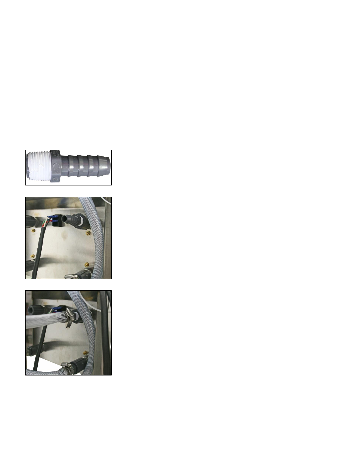
System Fluid Input Connection
The system input is to be setup so the connection can be easily disconnected and reconnected as necessary. The
following is the recommended connection detail.
Vessel and Pump Drains
The Membrane Vessel drains are located under the
membrane vessels. To drain the vessels remove the
heavy duty clamps and the caps. NOTE: Use caution
when removing clamps and caps as the membrane may
slide down out of the vessel as the cap is removed.
The feed pump drain is a 7/16” stainless steel plug
located on the front of the pump housing.
Pressure pump drain is a 7/16” stainless steel plug
located on the front of the pump housing.
1. Remove the PVC threaded plug from the end of the pump.
2. Obtain a 1” “F” style quick connector.
3. Teflon tape the threaded end.
4. Thread the “F” connector into the feed pump and tighten the connector.
5. Obtain a length of 1” braided hose that will connect to the strainer output.
6. Slide a 1” stainless steel band clamp over one end of the hose.
7. Slide the hose onto a 1” C style quick coupler and tighten the clamp over
the coupler.
8. Pull the metal latches on the quick coupler out to the sides (perpendicular
to the body of the quick coupler) then slide the open end of the coupler
over the F style coupler on valve V6.
9. Raise the metal latches on the quick coupler back to the side of the C quick
coupler while pressing the couplers together.
Leader Evaporator Springtech MicRO Reverse Osmosis System Manual YEAR: 2017 Page: 14
Concentrate and Permeate Outflow Connections
The connections to the outflow side of the concentrate and permeate flow meters are to ½” couplers located at the
top of the meters. The connections below describe one method connecting to the flow meters. If you are frequently
going to move the system and want to have added flexibility, use ½” “F” style quick connectors on the tops of the flow
meters and ½” “C” style quick couplers on the ends of the hoses to be connected to the flow meters. The method
below describes more permanent connection.
In order to assemble the connections you will need (all sold separately);
Two ½” PVC plastic to iron adapters,
Two (minimum) ½” Stainless Steel Band clamp,
½” ID braided food grade hose with length to make the connections for the Permeate and Concentrate tank.
The length of each hose should be sufficient to reach the wash tank.
Concentrate Flow Meter Connection
1. Teflon tape the threaded end of a ½” PVC plastic to iron adapter.
2. Thread the adapter into the top rear of the concentrate flow meter. The
flow meter is on the left hand side of the front panel. Tighten the
adapter.
3. Cut a length of ½” ID braided hose of sufficient length to connect to the
concentrate flow meter outflow connector to the concentrate tank or
the wash tank whichever length is greater.
4. Place at least one ½” stainless steel band clamp over the hose.
5. Slide the hose onto the barbed end of the ½” PVC plastic to iron adapter.
6. Position the stainless steel band clamp(s) over the hose on the adapter
and tighten the band clamps.
7. Place the open end of the hose into the concentrate tank.

Leader Evaporator Springtech MicRO Reverse Osmosis System Manual YEAR: 2017 Page: 15
Permeate Flow Meter Connection
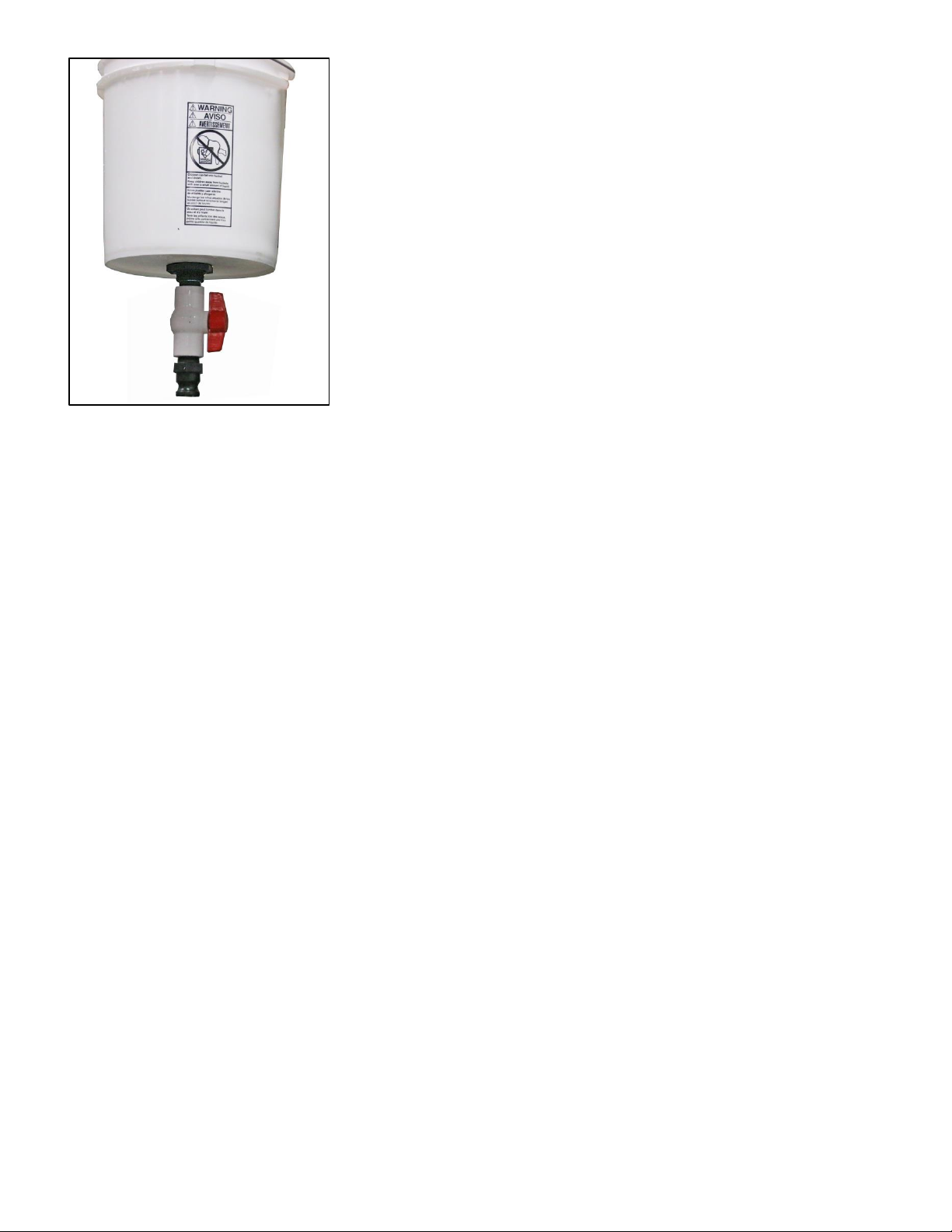
Wash Tank (To Be Supplied By User)
In order to properly maintain the membranes of the system, a wash cycle must be done on a periodic basis. A tank is
required in which the wash solution is mixed and then circulated through the system. A wash tank is not supplied with
the system but can be constructed by the user. One possible configuration is described below.
Materials Needed
Part Description
Leader Evaporator Order Number
Five gallon bucket made of food-grade material
5621
Braided hose –1” ID
70285 (by the foot)
PVC ball valve –1”
60130
Bulkhead fitting –1”
57002
PVC close nipple –1”
64329
Banjo “C” fitting –1” (2 required)
47148
Banjo “F” fitting –1”
47151
Stainless Steel #16 band clamp (min, 2 required)
60043
Teflon tape
66106
1. Teflon tape the threaded end of a ½” PVC plastic to iron adapter.
2. Thread the adapter into the top rear of the permeate flow meter. The
flow meter is on the right hand side of the front panel. Tighten the
adapter.
3. Cut a length of ½” ID braided hose of sufficient length to connect to the
permeate flow meter outflow connector to the permeate tank or the
wash tank whichever length is greater.
4. Place at least one ½” stainless steel band clamp over the hose.
5. Slide the hose onto the barbed end of the ½” PVC plastic to iron adapter.
6. Position the stainless steel band clamp(s) over the hose on the adapter
and tighten the band clamps.
7. Place the open end of the hose into the permeate tank.
Leader Evaporator Springtech MicRO Reverse Osmosis System Manual YEAR: 2017 Page: 16
1. Drill a hole in the bottom center of the bucket of sufficient size to
install the bulkhead fitting. Do not make the hole too large or the
bulkhead fitting will leak.
2. Install and tighten the bulkhead fitting into the prepared hole. The
Portion of the bulkhead fitting with the exterior threads should be on
the outside of the bucket.
3. Wrap both ends of the 1” PVC nipple with Teflon tape.
4. Screw one end of the 1” PVC nipple into the bottom of the bulkhead
fitting then tighten.
5. Thread the 1” PVC ball valve onto the other end of the 1” PVC close
nipple and tighten.
6. Teflon tape the threads of the Banjo “F” fitting and thread into the
other side of the 1” PVC ball valve.
7. Measure a length of 1” braided hose to reach between the wash tank and the input fitting on the feed pump of
the system.
8. Place a 1” stainless steel band clamp onto each end of the braided hose.
9. Insert a Banjo “C” fitting into each end of the braided hose and tighten the clamp.
10. Connect the quick couplers by opening the latch on the “C” style coupler (position the metal latch arms out
perpendicular to the body of the coupler) then sliding the “C” coupler onto the “F” coupler. Pull the metal
latch arms back up to the sides of the “C” coupler.
To use the wash tank, connect one end of the braided hose to the bottom quick coupler of the wash tank and the
other to the quick coupler on the feed pump of the system.
Leader Evaporator Springtech MicRO Reverse Osmosis System Manual YEAR: 2017 Page: 17
OPERATION
NOTE: Always STOP the system prior to changing the positions of any hoses.
Starting the System
For any cycle to be run the following is the startup sequence.
1. Open the top valve
2. Place the Pressure Switch (located in the center of the front
panel) in the START (Down) position.
3. Start the feed pump (bottom pump)
4.Run the feed pump until most of the air has been purged from
the flow meters on the front of the machine.

Leader Evaporator Springtech MicRO Reverse Osmosis System Manual YEAR: 2017 Page: 18
5. Start the pressure pump (upper pump).
6. Place the Pressure Switch in the RUN (Up) position.
7. Using the valve on the top of the right side membrane, adjust
to the desired flow rate.
Reset For Low Pressure Shutoff
Low pressure shutoff will occur when the flow of fluid into the system has been interrupted (generally when the sap or
permeate tank has been emptied).
DO NOT SHUT OFF THE PRESSURE SWITCH BEFORE SHUTTING OFF THE PUMPS

Leader Evaporator Springtech MicRO Reverse Osmosis System Manual YEAR: 2017 Page: 19
1. Shut off the pressure pump (pump #2)
2. Shut off the feed pump (pump #1)
3. Place the Pressure Switch (located at the center of the control panel) in
the START (Down) position.
Normal Shutdown
1. Place the Pressure Switch (located at the center of the control panel) in
the START (Down) position.
2. Shut off the pressure pump (pump #2)

Leader Evaporator Springtech MicRO Reverse Osmosis System Manual YEAR: 2017 Page: 20
3. Shut off the feed pump (pump #1)
Initial System Cleaning
To prepare the system after setup;
1. Put approximately 250 US gallons for a two membrane system (125 gallons for a one membrane system) of
non-chlorinated well or spring water into a clean permeate storage tank.
2. Place the output hoses from the permeate and concentrate meters so they will go to drain. Place the incoming
hose to the feed pump so it will draw permeate water from the permeate tank. Run a rinse cycle (see page 28)
using a minimum 125 US gallons of water (63 gallons for a one membrane system) from the permeate tank.
While this cycle is running check all fittings, piping, connections and hoses for leaks. Repair as necessary.
3. At the end of the rinse cycle change, move the permeate and concentrate meter outflow hoses so the liquid
flow into the wash tank. Fill the wash tank to approximately ⅔ full.
4. Mix alkaline R/O soap with the liquid in the wash tank until the required is reached. To determine the required
pH, refer to the Serial Number Data Sheet that initially accompanied the system. NOTE: If the membrane(s) is
(are) changed, reference the data sheet accompanying the new membrane(s).
5. Connect the wash tank to the feed pump and run an alkaline wash cycle (see page 29). Run the system until a
temperature of 118°F when measured in the wash tank.
6. Place the output hoses from the permeate and concentrate meters so they will go to drain. Place the incoming
hose to the feed pump so it will draw permeate water from the permeate tank. Run a rinse cycle (see page 28)
using a minimum 125 US gallons of water (63 gallons for a one membrane system) from the permeate tank.
Run the benchmark permeability test (see page 21).
Sampling
In order to determine the sugar % in either the sap or the concentrate;
1. Fill a test cup with the liquid to be measured.
2. Pour the liquid back into the sap tank.
3. Fill the test cup and slowly lower a sap hydrometer into the liquid and read the results.
NOTE: Alternately a sap refractometer (digital or optical) can be used. Make sure they are clean prior to placing the
liquid sample on the instrument.
Data Logging
Data on the operation of the system should be recorded and kept. See ATTACHMENT #1 for the data sheet format.
The following data is recorded:
Date –date the information is collected
Activity –Concentration cycle (enter a “C”) or Test (enter a “T”)
Sap % - the sugar concentration of the raw sap
Concentrate % - the sugar concentration of the concentrate from the system –test results from the
concentrate meter output
Permeate Flow –gallons per minute of permeate from membrane flow meter –reading from the top of the
stainless steel float in the permeate flow meter
Table of contents
Other Leader Evaporator Industrial Equipment manuals


Popular Industrial Equipment manuals by other brands


ABB
ABB Power2 650-M46 Operation manual

Wittenstein Alpha
Wittenstein Alpha SP+ operating manual

BLUM
BLUM MINIPRESS Safety instructions, set-up instructions and instruction leaflet

Sungrow
Sungrow MVS6250 Transportation and Installation Guide

Woodward
Woodward easYgen-3000XT Series Option manual

Axiom
Axiom CNC Series Assembly manual


