Axiom CNC Series User manual

1
BG Precision
Date: 28 July 2019
Axiom CNC Safety Enclosure
Assembly Manual

2
Manufacturer:
AXIOM PRECISION
AXIOM TOOL GROUP
TAIWAN
Agent and Appointed Reseller
BG Precision PTY LTD
Unit 1/82 Brunel Road
SEAFORD
3198 VIC
Australia
Mob: +61 (0)405685515
Email: info@bgprecision.com.au
Website: www.bgprecision.com.au
Before using/turning on the machine, the device should be carefully checked to make sure all
connections are secure and the device is technically sound.
WARNING
Read & understand
operators manual before
using this machine.
Failure to follow operating
instructions could result in
death or seriousinjury

3
1 INTRODUCTION
Thank you for purchasing your AXIOM CNC Safety Enclosure system. Firstly, please inspect
the machine and all components after deliver has been received. Please check and ensure all
aspects of the machine and associated extra items are in good condition and there is no
evidence of damage or wear to any components due to the shipping process.
Please ensure you read the operational manuals for this AXIOM CNC router machine prior to
attempting to use the system.
Responsibility of use or misuse belongs to the end user. BG Precision PTY LTD and its
affiliates accept no responsibility for use or misuse by the user. If you may not be able to use
this product properly, we recommend that you do not begin use or cease use immediately.
If there are any further questions or if anything is not clear, please contact us at
info@bgprecision.com.au
ENCLOSURE DESCRIPTION
The enclosure has been constructed to ensure the safe operation of your CNC System. The
machine placed in the interior is accessible from two sides via the dual interlocked doors on
the front and left-hand side of the enclosure. This allows access to all areas of your machine
bed for maintenance, material clamping, tool changing and/or material loading. The
interlocking doors ensure while the machine is active you cannot access the interior of the
enclosure as the doors have a mechanical locking feature. To do so you must engage the reset
condition for your CNC to allow the doors to open.
Placed on the left-hand side of the front and side doors is an E-Stop. Engaging this E-Stop will
activate your reset condition and stop the machine from any operation. The main safety control
panel is located on the front of the enclosure. This help you monitor the current state of the
safety enclosure with a green LED when lit, indicating the machine is active.
The enclosures electronics are all integrated with your CNC Controller to monitor these
conditions. If a door is open or an E-stop is triggered the UCCNC software will not allow you
to activate the machine.

4
Figure 1 Axiom AR8 with full Safety Enclosure and additional touch screen display
HANDLING YOUR AXIOM CNC MACHINE
The CNC router table assembly is heavy. Please use a secure means and use
caution when lifting onto the stand. At least 3-4 able bodies persons are
needed to lift the machine onto the stand.
To avoid damage, be careful to never lift the router by the gantry. Always lift the
Axiom CNC machine under the black steel frame. You should sight under your
Axiom CNC Table (Figure 2); the y-axis profile linear rails and y-axis ballscrew.
If these precision components are damaged you must send the CNC machine back to the
workshop for replacement.
Figure 2 Underside of Axiom CNC Machine

5
ALUMINIUM PROFILE ASSEMBLY HINTS

6
Figure 3 Corner Alignment
When connecting two aluminium extrusion components together you must ensure a square
and flush fit. We achieve this by placing a straight edge across the joint while tightening the
pre-tensioning anchor grub screw. This is very important to all the enclosure components
aligning correctly.

7
2 STEP 1–SETTING UP THE STAND
Failure to read and understand all the assembly and setup instructions before
attempting assembly may result in serious injury.
Once you have verified the machine and their contents are 100%okay anddamage
free after transport then you can begin the setup process.
STAND CONTENTS
Figure 4 Axiom Stand Packaging Figure 5 Axiom Stand contents
Packaging contents for the Axiom Precision Stand (ARS400/600/800):
2-Stand upright (front & back)
2-Cross braces
1-Lower shelf plate
1-Stand hardware package
Hardware package contains:
4-Swivel casters
4-Leveling Feet
4-hex nuts
16-Hex bolts (M8x25)
16-Lock washers (M8)
16-Flat washer (M8)
16-Hex bolts (M6x12)
16-Lock washer (M6)
16-Flat washer (M6)
1-Controller hook
2-Machine screws (M4x6)
4-Small rubber pads
Figure 6: AXIOM steel stand assembly overview
Figure 7 Hardware package contents

8
Figure 8: Castors and feet
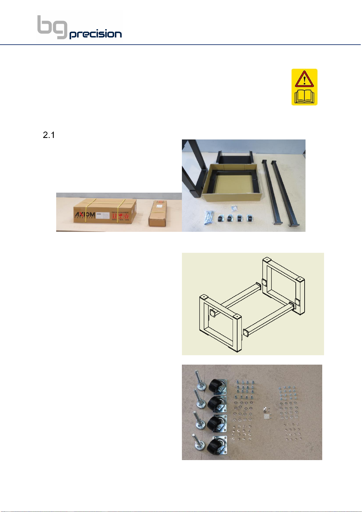
Remove all contents from shipping boxes. Do not discard carton or packing material until
assembly is complete. Accessories commonly ship inside machine or stand packaging and
can be easily over looked.
STAND ASSEMBLY
Tools required for assembly:
#2 Philips-Screwdriver
10mm, 13mm and 17mm sockets and socket wrench
24mm open-end wrench
2mm and 3mm Allen key
Spirit Level
Assembling Stand (all models):
Assembly for stand fitting all Basic and Pro model machines is the same. The only difference
is the length of the cross braces.
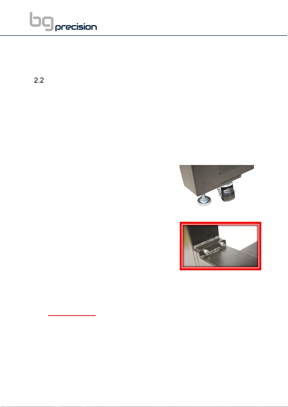
1- Thread a loose hex-nut onto each of the levelling feet.
2- Turn the square stand uprights upside down. Do this on
top of the cardboard packaging to prevent scratching.
a. Install the levelling feet and swivel casters using
M6 hex bolt, M6 lock washer, and M6 flat washer
for each caster. Tighten all the caster hardware
securely. The levelling feet can be adjusted later.
b. Rotate uprights so the cross-brace mounting plates
are facing each other. Separate the uprights far
enough that the braces can fit between them.
c. Align the cross-braces between the uprights and
bolt the mounting flanges to the plates using (4) M8
hex bolt, (4) lock washers and (4) flat washers for each side. We recommend that
you do not fully tighten these bolts until the machine is securely fixed on top of the
stand as this makes the machine and stand alignment easier.
IMPORTANT NOTE: As seen in the diagram above (Figure 9), the braces should be
rotated correctly for the toolbox and shelf to sit at the correct height. Braces
should be mounted so that the top and bottom are the larger flat surfaces*
3- With assistance, the stand can now be flipped over onto the casters and levelling feet.
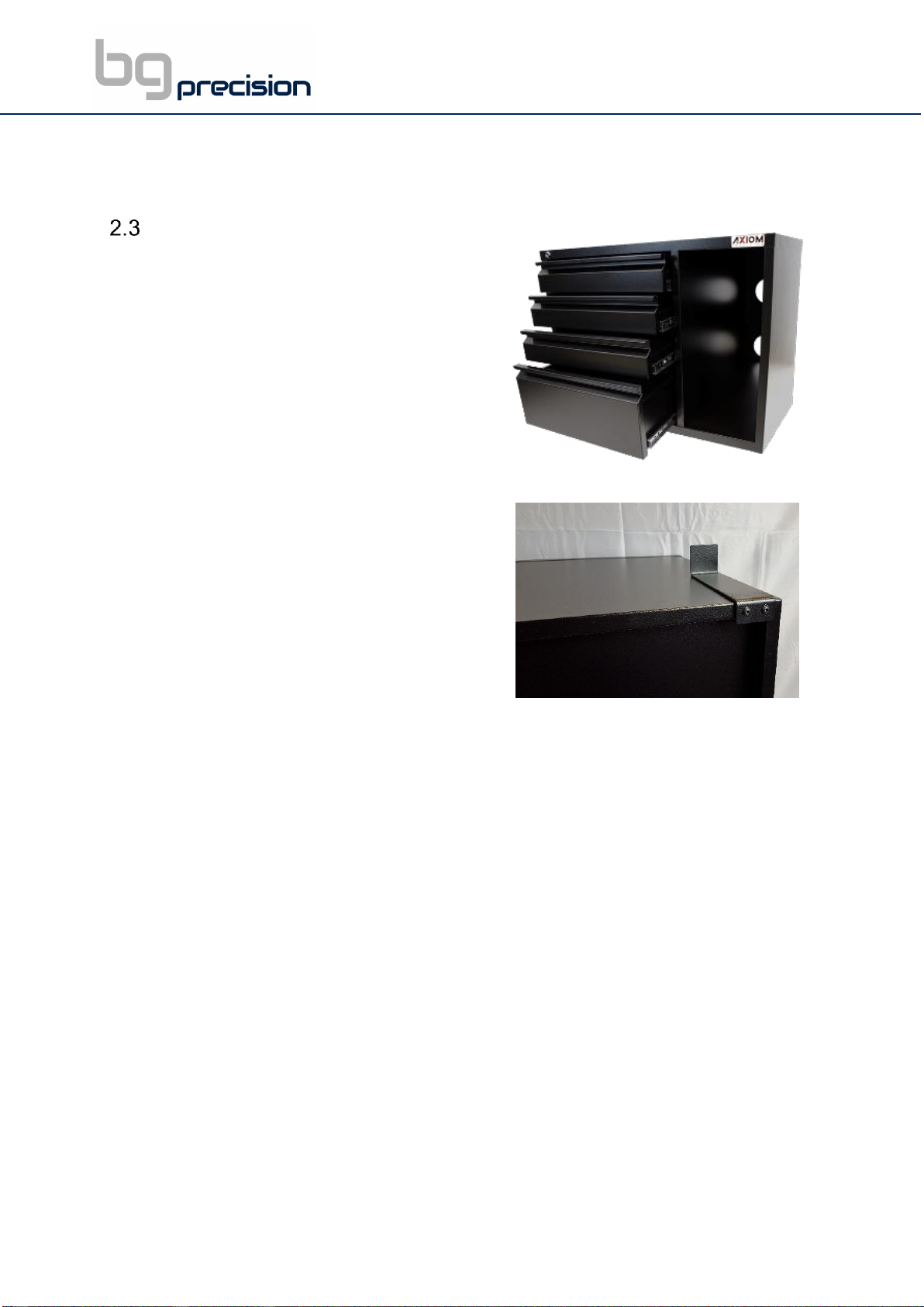
4- Flip the shelf upside down and stick of the rubber pads on each corner of the shelf flange.
a. Install shelf between the braces on the stand, all the way forward.
Figure 9: Bolted connections for stand

9
b. The small rubber pads should now be between the flange and the top surface of the
brace. This will help prevent unwanted movement and scratching.
AXIOM TOOLBOX
1- Turn the tool-box upside down. Install (1) of
each hanger on either side of the toolbox using
the installed rivnuts and (2) 3mm cap-screw
each.
2- Insert the toolbox into the stand, from the top.
The hangers will with snugly between the
braces on either side of the toolbox.
3- The front can be slid forward to rest within the
opening on the stand upright.
Figure 10: Toolbox
Figure 11: Hangers for toolbox

10
ENCLOSURE BASE ASSEMBLY
The final step of the setting up the stand assembly is fixing the machine enclosure base to the
stand. To assist with locating the assemblies correctly we have provided 4 x M4x10mm screws
that should be used to help align the enclosure base assembly to the stand assembly (See
Figure 12). If the hole alignments are not correct, we suggest you loosen the bolts on the stand
cross member as per Figure 9 above. Please take note of Figure 14 for orientation.
Figure 12 M4 Locator Screw Figure 13 Base Assembly and stand Alignment
Step 1 is complete when your assembly looks like Figure 14
Figure 14: Final Stand and enclosure base
assembly

11
3 STEP 2-INSTALLING THE ROUTER TABLE ON THE STAND
The CNC router table assembly is heavy. Please use a secure means and use caution when
lifting onto the stand. At least 3-4 able bodies persons are needed to lift the machine onto the
stand.
To avoid damage, be careful to never lift the router by the gantry. Always lift the Axiom CNC
machine under the BLACK STEEL FRAME. You should sight under your Axiom CNC Table;
the y-axis profile linear rails and y-axis ballscrew. If these precision components are damage
you must send the CNC machine back to the workshop for replacement. If required to lift via
the Aluminium T-Slot Table, you must only lift closest the black steel frame and never any
further from it than a hands width away. See Figure 15 Lifting the Axiom CNC.
Figure 15 Lifting the Axiom CNC

12
If using a forklift, keep forks under the black steel frame to avoid damaging the wiring and
mechanics of the machine. Place a scrap piece of lumber beneath the router assembly and
carefully slide forks beneath the steel base.
Figure 16: Ensure forks extent the entire way across the machine
IMPORTANT NOTE Make sure the forks extend through to the other side
of the machine for safe lifting. See Figure 16 for more detailed info. It’s
IMPERATIVE you lift only from the steel frame.

13
1- Position router over the stand and align holes on router mounting flanges and the enclosure
base assembly holes being careful to make sure the stand is properly oriented with the
machine front. Stand front is the side you placed the toolbox in as per Figure 17.
Figure 17 Installing the Router Table on the Stand
2- Place rubber bushing over the holes in the stand. Lower the machine to sit on the
bushings.
a. Attach the machine to the stand using M10 Hex bolt provided with washer at
each corner.
b. Insert the bolt/washer through the machine mounting flange and the rubber
bushing.
c. Thread the bolt loosely into the stand mounting holes. Do not tighten until all
bolts have been threaded. This ensures correct alignment.
d. Remove fork lift and tighten bolts evenly.
Figure 18 Correct fixing of router table to stand assembly

14
3- When the Router Table is securely fixed to the enclosure base and stand assembly
you can then proceed to tighten the 4 bolts at each end of the stand cross members.
Figure 19 Stand cross member bolts
4- Now is a good time to place your control box into its correct location in the toolbox
and feed all the connection cables through the hole at the back
Figure 20 Axiom Controller in toolbox Figure 21 Connection Cables
5- Connect the two barrel connections to the back of the Router Table as per Figure 22.
Leave the mains plug disconnected until the full enclosure assembly is complete.
Figure 22 Machine Connections
Step 2 is now complete.

15
4 STEP 3-ENCLOSURE ASSEMBLY
1- The first step of the enclosure assembly is the front left corner upright. Ensure it is flush
with cross-member and tighten accordingly. Please note orientation of hinge brackets.
Figure 23 Front Left Upright
2- The second step is the right-hand side assembly. Ensuring the front hinges as facing
in towards the centre of the machine slide the right-hand side assembly along the
enclosure base cross members as per the picture shown.
Figure 24 LHS assembly Figure 25 LHS assembly complete

16
3- Now proceed to the back of the machine. The rear assembly should be positioned as
shown making sure the hinges are positioned in towards the machine for the side doors.
Take care of the barrel connections at the back of the machine. There are two black
brackets to hold the polycarbonate in place that can be secured to the side installed
previously. Take care not to overtighten the screw on the clear polycarbonate.
Figure 26 Rear Enclosure Assembly Figure 27 Barrel Connections
Figure 28 Rear Assembly Complete

17
4- Now we can fit the single front bottom cross member as per the pictures shown. Take
note that the magnetic door stops should be facing up. Again, it is very important to
ensure all connections are flush on both sides
Figure 29 Bottom front cross member Figure 30 Bottom front cross member complete
5- Now we can proceed to hang the doors. Make sure you have the correct door in the
correct location before hanging. This can be done by placing them as per the picture
below before lifting them in place.
Figure 31 Door Locations

18
Figure 32 Doors Fitted
6- Place the top assembly as shown in the picture below. This step may require a few
hands and a safe working platform to reach the top of the enclosure.
Figure 33 Preparation for top assembly

19
With the doors shut the step will be easier to allow the top assembly to rest in place.
Figure 34 Top assembly Location
7- Remove the bubble wrap and position the control electronics in place as per the
pictures below. You can pop out the slot covers to place the electronic cable in neatly
inside.
Figure 35 E-Stop Location at rear Figure 36 Safety Enclosure Main Controller

20
8- Now you can secure each corner of the top assembly the four uprights. You must
ensure a flush connection for perfect enclosure alignment.
Figure 37 Top Assembly Complete
Table of contents
Other Axiom Industrial Equipment manuals
Popular Industrial Equipment manuals by other brands

Siemens
Siemens Worm Gearbox S 5 BA 2012 operating instructions

Siemens
Siemens SIMOGEAR BA 2030 Translation of the original operating instructions

Tormach
Tormach 51136 installation guide

Bosch
Bosch TS0800 quick start guide

Flight Systems
Flight Systems MODEL100 user manual

Conductix-Wampfler
Conductix-Wampfler ProfiDAT compact Mounting instructions

AeroClave
AeroClave RDS 3110 Operator's manual

Wilo
Wilo SiBoost Smart 1 Series Installation and operating instructions

TSI Instruments
TSI Instruments MSP 200 user guide

Vestil
Vestil PM5-BR Use and maintenance instructions

Allen-Bradley
Allen-Bradley 198E-AYTJ2 installation instructions

RHINO
RHINO HPP18V FLEX operating manual