Leader MULTIFLOW CMFA-0530-LI User manual

1

2
Product reference
MULTIFLOW
FLOWMATIC
MULTIMATIC
See models on pages 13/14/15

3
This manual was designed to familiarise you with the use of the nozzle.
The instructions for use and safety guidelines must be followed in order to
prevent accidents. Any disassembly or repair must be performed by either
LEADER or an approved dealer.
This manual presents the simplicity and ease of use of the nozzle. In order to
improve this manual LEADER remains open to your suggestions. Please do not
hesitate to contact us.

4
1INTRODUCTION 5
2SAFETY INSTRUCTIONS 6
3REFERENCE 7
4DESCRIPTION 8
5FEATURES 12
5.1General information 12
5.2MULTIFLOW model 13
5.3FLOWMATIC model 14
5.4MULTIMATIC Model 15
6REQUIREMENT 16
7USING THE DEVICE 17
7.1Implementing the standard handle nozzle 17
7.2Implementing the TriggerFlow nozzle 18
8FLOW RATE DIAGRAM - PRESSURE 19
8.1MULTIFLOW model 19
8.2FLOWMATIC model 20
9MAINTENANCE 21
10EXPLODED VIEW 21
11WARRANTY 22

5
1 INTRODUCTION
This nozzle meets your needs by its ease of use and efficiency.
This nozzle allows you to select its type of fitting, body, head, and colour.
▪The choice between several head types:
▪MULTIFLOW: nozzle with flow selection.
▪FLOWMATIC: nozzle with pressure regulator.
▪MULTIMATIC: nozzle with several pressure settings.
▪The choice between several body types:
▪Aluminium body with a standard handle.
▪Aluminium body with a trigger handle or without a protective hoop.
▪A range of colours to suit your taste:
▪Red is the default colour for MULTIFLOW nozzles.
▪Blue is the default colour for MULTIMATIC and MULTIFLOW nozzles.
▪Orange.
▪Green.
▪Yellow.
▪A choice of misting gear teeth:
▪Machined gear teeth.
▪Turbined.

6
2 SAFETY INSTRUCTIONS
▪This equipment is manufactured in accordance with European directives and
NF EN 15182.
▪Its use is restricted to firefighting professionals.
▪Please read this manual thoroughly along with the instructions for use before
commissioning and using the equipment.
▪Do not exceed 40 bars of input pressure.
▪Only qualified and trained personnel should operate or repair this device.
▪Always replace a defective part by an original part provided by LEADER.
▪The device should not be disassembled when pressurised.
▪Keep the device away from children.
▪The use of the nozzle to spray water on the protective clothing of a team members
subjected to heat radiation is prohibited.
▪Never allow someone to use the device without having provided them with the necessary
instructions.
▪Do not leave water inside the gun if there is a risk of freezing.
▪Rinse with clean water after use with seawater, brackish water, or additive water.
▪Do not disconnect the device from the hose without first making sure the pressure is off.
▪A rapid closing of the spray gun can lead to a water hammer effect detrimental to the
device.
▪Clean the filter of all debris after each use.
▪The reaction force of the spray gun must be taken into account. This must be anticipated
when the operator turns it on.
▪Use a fitting in line with the thread of the nozzle.
▪Do not use the nozzle on high-voltage wires.
IMPORTANT

7
3 REFERENCE
C: Compact
MF: MultiFlow
A: Aluminium
G: TriggerFlow
0: Without protective hoop
1: With protective hoop (Only on TriggerFlow)
5: Without turbine
7: With turbine
30: 150 lpm
31: 235 lpm
32: 400 lpm
33: 40 gpm
34: 60 gpm
35: 125 gpm
52: 470 lpm@7b
LI: 1” F – BSP
1L: 1’’ F – NH
MI: 1.5" F –BSP
TI: 1.5" F –NPSH
RI: 1.5" F –NH
EI: 2’’ M – BSP
R: Red
B: Blue
O: Orange
G: Green
Y: Yellow
TriggerFlow is
only in Red
FM: FlowMatic
36: Ring –150 lpm@6b
37: No ring –150 lpm@6b
38: Ring –250 lpm@6b
39: No ring –250 lpm@6b
40: Ring –400 lpm@6b
41: No ring –400 lpm@6b
42: AA - no ring –400 lpm@6b
43: No ring –125 gpm@100PSI
56: Ring–125 gpm@100PSI
MM: MultiMatic
45: Puls –125 gpm
46: Puls –400 lpm
47: Puls –Low –400 lpm
48: Puls –Low –125 gpm
49: Low –400 lpm
50: Low –125 gpm
C FM A-0 5 38-RI B

8
4 DESCRIPTION
Standard handle nozzle
TriggerFlow nozzle
Hard anodized
aluminium body
Grab handle
Rotating input
connector
Flow selector ring
Machined aluminium
gear teeth.
Tactile detection of maximum
flow
Spray selector head with shock
protection
Jet Attack tactile
flow detection
Handle grip
Rotating input
connector
Hard anodized
aluminium body
Opening lock button
Input filter
Trigger opening
Handle grip
Protective hoop
Spray selector head with
shock protection

9
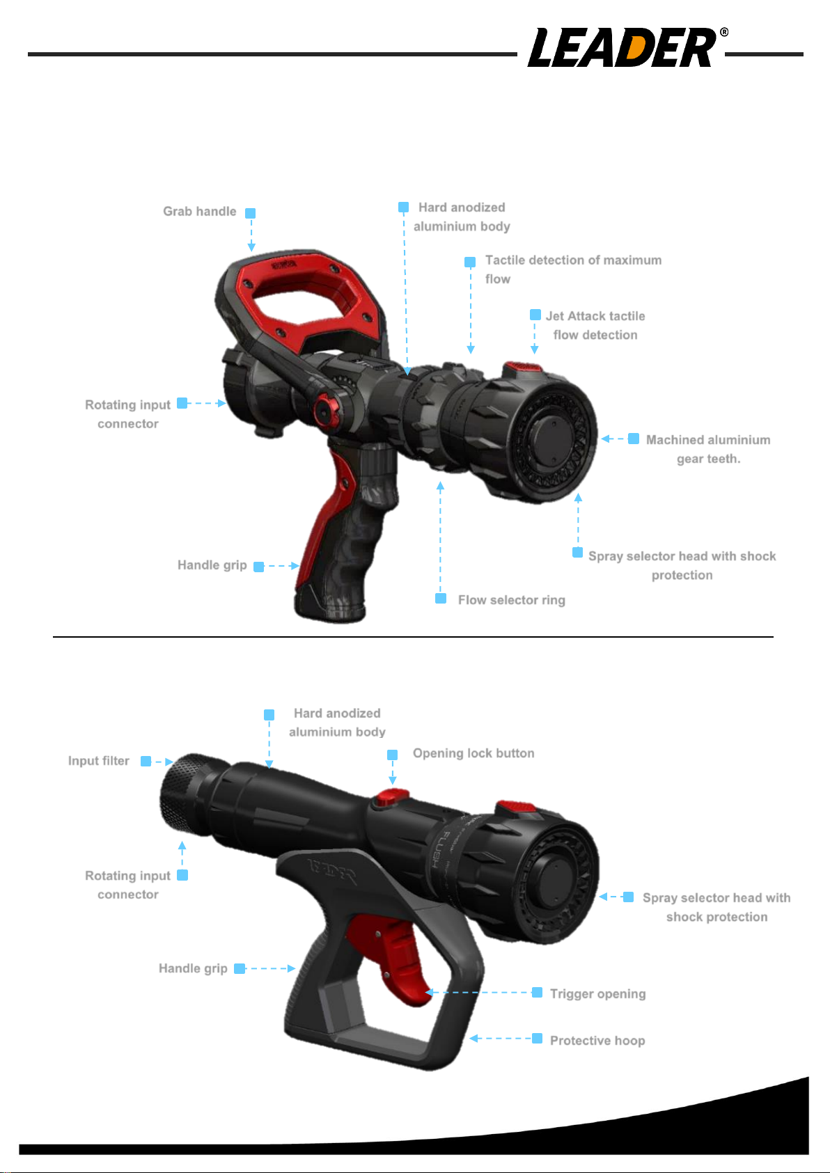
➢ALUMINIUM body with a Standard handle:
▪AGS T5 aluminium alloy construction.
▪Protection against mechanical and chemical attack by 50μ hard
anodization and Teflon impregnation.
▪Protection against shocks thanks to its heat and cold resistant
polyurethane head sheath. Excellent thermal insulation.
▪Its ergonomic grip is made of non-slip polyamide.
▪Stainless steel pins and screws.
▪Ergonomic handle.
➢ALUMINIUM body with a Trigger handle:
▪AGS T5 aluminium alloy construction.
▪Protection against mechanical and chemical attack by 50μ hard
anodization and Teflon impregnation.
▪Protection against shocks thanks to its heat and cold resistant
polyurethane head sheath.
Excellent thermal insulation.
▪Its ergonomic grip is made of non-slip polyamide.
▪Protective hoop (optional).
▪Stainless steel pins and screws.
▪Ergonomic handle.
➢Interchangeable handles:
▪Facilitates identifying the device after an intervention.
▪Possibility for users to choose the colour of the
handle grip between Red, Yellow, Orange, Blue, and
Green.
This option is valid on devices having a standard
aluminium handle.

10
➢Valve:
▪Quick opening and closing with the Standard handle.
▪Quick opening and closing with the Trigger handle.
➢Nominal Pressure:
▪40 bars.
➢Protection filter:
▪Protects against debris at the inlet connection.
NB: 1" British standard pipe (BSP) connectors are not equipped with a filter.
➢Purge:
▪Manoeuvrable during operation, this enables evacuating debris that may have passed
through the filter. The purge can be triggered either by means of the flow ring in the
"FLUSH" position or by rotating the head beyond the protective spray.
➢Inlet connection:
▪Rotating 360°, various choices possible.
•Female 1" BSP.
•Female 1" NH.
•Female 1.5" BSP.
•Female 1.5" NH.
•Female 1.5" NPSH.
•Male 2" BSP.
➢Spray:
▪The spray system can be selected either with
machined gear teeth in aluminium or turbine in
stainless steel.
Turbine spray
Spray by machined
gear teeth

11
Normative device type
and marking
Flow rate
selector
Spray shape and
serial number
Tactile detection of
maximum flow
Flow
rates
FLUSH
Tactile detection of
attack spray
➢Adjustable spray:
▪The rotation of the head ring makes it possible to switch from a wide cone-like spray at
130° wide, gradually reduced to a 50° narrow spray then up to a full spray position.
▪Tactile and visual detection enable determining the shape of the selected spray.
▪Engravings.
➢Various models:
➢Option:
MULTIFLOW
Adaptable spray shape with an adjustable flow.
By simply rotating a flow selector ring.
This ring has the flow rates engraved on it :
20-40-100-150 lpm / 70-130-230-400 lpm…
5-10-24-40 gpm / 30-60-95-125 gpm…
"FLUSH" This corresponds to the Flush position. It is used to evacuate
any debris stuck inside the device.
Tactile detection allows identifying the position of the maximum flow rate
setting.
FLOWMATIC
Adaptable spray shape with constant pressure.
MULTIMATIC
Adaptable spray shape with constant pressure and adjustable constant
flow.

12
▪LEADER spray gun handles can be equipped with a multi-expansion foam generator
(Low and Medium).
5 FEATURES
5.1 General information
•Manufacturer: LEADER
•Size: COMPACT
•Operation under
nominal pressure: PN 40
•Type of spray: Diffusion alternating between hollow cone / solid cone
•Valve: Sliding valve
•Protective filter: Against debris at the inlet connection
L
h
L
h
l
l

13
5.2 MULTIFLOW model
Type is according to Annex A of EN 15182-1: Type 3.
Type
according to
EN 15182
Reference
Flow rates
Body
Gear
teeth
Inlet
Mass
kg (±0.2)
Length
L (mm)
Width
l (mm)
HT
h (mm)
MULTIFLOW
Type 3
CMFA-0530-LI
20-40-100-150 lpm
Aluminium
Fixed
1" F BSP
1.74
270
117
232
CMFA-0530-EI
2" M BSP
1.79
309
117
232
CMFG-1530-LI
TriggerFlow
Fixed
1" F BSP
2.34
325
87
209
CMFG-1530-EI
2" M BSP
2.39
356
87
209
CMFA-0531-LI
40-100-150-235 lpm
Aluminium
Fixed
1" F BSP
1.74
270
117
232
CMFA-0531-EI
2" M BSP
1.79
309
117
232
CMFG-1531-LI
TriggerFlow
Fixed
1" F BSP
2.338
325
87
209
CMFG-1531-EI
2" M BSP
2.39
356
87
209
CMFA-0532-MI
70-130-230-400 lpm
Aluminium
Fixed
1.5" F BSP
1.76
285
117
232
CMFA-0532-EI
2" M BSP
1.79
309
117
232
CMFG-1532-EI
TriggerFlow
Fixed
2" M BSP
2.39
356
87
209
CMFA-0752-MI
470 lpm @ 7 bars
Aluminium
Turbine
1.5" F BSP
1.03
270
117
232
CMFA-0533-1I
5-10-24-40 gpm
Aluminium
Fixed
1" F NH
1.74
270
117
232
CMFA-0733-1I
Turbine
1" F NH
1.74
270
117
232
CMFG-1533-1I
TriggerFlow
Fixed
1" F NH
2.34
325
87
209
CMFG-1733-1I
Turbine
1" F NH
2.38
325
87
209
CMFA-0534-RI
10-24-40-60 gpm
Aluminium
Fixed
1.5" F NH
1.76
285
117
232
CMFA-0734-RI
Turbine
1.5" F NH
1.8
285
117
232
CMFG-1534-RI
TriggerFlow
Fixed
1.5" F NH
2.18
340
87
209
CMFG-1734-RI
Turbine
1.5" F NH
2.22
340
87
209
CMFA-0535-RI
30-60-95-125 gpm
Aluminium
Fixed
1.5" F NH
1.76
285
117
232
CMFA-0735-RI
Turbine
1.5" F NH
1.8
285
117
232
CMFA-0735-TI
1.5" F NPSH
1.8
285
117
232
CMFG-1535-RI
TriggerFlow
Fixed
1.5" F NH
2.18
340
87
209
CMFG-1735-RI
Turbine
1.5" F NH
2.22
340
87
209

14
5.3 FLOWMATIC model
Type is according to Annex A of EN 15182-1: Type 4.1.
Type
according to
EN 15182
Reference
Flow rates
Body
Gear
teeth
Inlet
Mass
kg (±0.2)
Length
L (mm)
Width
l (mm)
HT
h (mm)
FLOWMATIC
Typ
e 4.1
CFMA-0536-LI
0-150 lpm @ 6 bar
Aluminium
Fixed
1" F BSP
1.75
270
117
232
CFMA-0536-EI
Aluminium
2" M BSP
1.79
309
117
232
CFMA-0537-LI
Aluminium
Fixed
1" F BSP
1.75
251
117
232
CFMA-0537-EI
Aluminium
2" M BSP
1.79
290
117
232
CFMG-1537-LI
TriggerFlow
Fixed
1" F BSP
2.25
306
87
209
CFMG-1537-EI
2" M BSP
2.3
337
87
209
CFMA-0538-LI
0-250 lpm @ 6 bar
Aluminium
Fixed
1" F BSP
1.75
270
117
232
CFMA-0538-EI
2" M BSP
1.79
309
117
232
CFMA-0539-LI
Aluminium
Fixed
1" F BSP
1.75
251
117
232
CFMA-0539-EI
2" M BSP
1.79
290
117
232
CFMG-1539-LI
TriggerFlow
Fixed
1" F BSP
2.25
306
87
209
CFMG-1539-EI
2" M BSP
2.3
337
87
209
CFMA-0540-MI
0-400 lpm @ 6 bar
Aluminium
Fixed
1.5" F BSP
1.76
285
117
232
CFMA-0540-EI
2" M BSP
1.79
309
117
232
CFMA-0541-LI
Aluminium
Fixed
1" F BSP
1.75
251
117
232
CFMA-0541-MI
1.5" F BSP
1.76
266
117
232
CFMA-0541-EI
2" M BSP
1.79
290
117
232
CFMG-1541-MI
TriggerFlow
Fixed
1.5" F BSP
2.27
321
87
209
CFMG-1541-EI
2" M BSP
2.3
337
87
209
CFMA-0542-MI
Aluminium
AA
Fixed
1.5" F BSP
1.8
266
117
232
CFMA-0542-EI
2" M BSP
1.8
290
117
232
CFMA-0543-RI
125 gpm @ 100 psi
Aluminium
Fixed
1.5" F NH
1.76
266
117
232
CFMA-0743-TI
Aluminium
Turbine
1.5" F
NPSH
1.8
266
117
232
CFMA-0743-RI
Aluminium
1.5" F NH
1.8
266
117
232
CFMG-1543-RI
TriggerFlow
Fixed
1.5" F NH
2.27
321
87
209
CFMG-1743-TI
Turbine
1.5" F
NPSH
2.3
321
87
209
CFMG-1743-RI
1.5" F NH
2.3
321
87
209
CFMA-0556-RI
Aluminium
Fixed
1.5" F NH
1.76
285
117
232

15
5.4 MULTIMATIC Model
Type is according to Annex A of EN 15182-1: Type 4.2
Type
according to
EN 15182
Reference
Flow rates
Body
Gear teeth
Inlet
Mass
kg (±0.2)
Length
L (mm)
Width
l (mm)
HT
h (mm)
MULTIMATIC
type
4.2
CMMA-0545-TI
0- 125 gpm
Pulsing
Aluminium
Fixed
1.5" F NPSH
1.758
285
117
232
CMMA-0546-LI
0-400 lpm
Pulsing
Aluminium
Fixed
1" F BSP
1.742
270
117
232
CMMA-0546-MI
1.5" F BSP
1.758
285
117
232
CMMA-0546-EI
2" M BSP
1.79
309
117
232
CMMG-1546-EI
TriggerFlow
Fixed
2" M BSP
2.386
356
87
209
CMMA-0547-MI
0-400 lpm
Pulsing Low
Pressure
Aluminium
Fixed
1.5" F BSP
1.758
285
117
232
CMMA-0547-EI
2" M BSP
1.79
309
117
232
CMMG-1547-EI
TriggerFlow
Fixed
2" M BSP
2.386
356
87
209
CMMA-0548-TI
125 gpm
Pulsing Low
Pressure
Aluminium
Fixed
1.5" F NPSH
1.758
285
117
232
CMMA-0548-RI
1.5" F NH
1.758
285
117
232
CMMG-1548-TI
TriggerFlow
Fixed
1.5" F NPSH
2.354
340
87
209
CMMG-1548-RI
1.5" F NH
2.354
340
87
209
CMMA-0549-MI
0-400 lpm
Low
Pressure
Aluminium
Fixed
1.5" F BSP
1.758
285
117
232
CMMA-0549-EI
2" M BSP
1.79
309
117
232
CMMG-1549-MI
TriggerFlow
Fixed
1.5" F BSP
2.354
340
87
209
CMMG-1549-EI
2" M BSP
2.386
356
87
209
CMMA-0550-RI
125 lpm Low
Pressure
Aluminium
Fixed
1.5" F NH
1.758
285
117
232
CMMA-0750-TI
Turbine
1.5" F NPSH
1.758
285
117
232
CMMA-0750-RI
1.5" F NH
1.758
285
117
232
CMMG-1750-TI
TriggerFlow
Turbine
1.5" F NPSH
2.354
340
87
209
CMMG-1750-RI
1.5" F NH
2.354
340
87
209
CMMG-1550-RI
Fixed
1.5" F NH
2.354
340
87
209

16
6 REQUIREMENT
Standards
Post
Test results
CONTROL AND OPERATION
EN 15182-2 /4.2.1
Dimensions (mm).
See previous table
EN 15182-2 /4.2.1
Mass (kg).
See previous table
EN 15182-2 /4.2.2
Torque required to operate the handle.
2 N.m
EN 15182-2 /4.2.2
Torque required to operate the flow control ring.
2.5 N.m
EN 15182-2 /4.2.2
Torque required to operate the spray adjustment ring.
2.25 N.m
EN 15182-2 /4.2.2
Torque required to operate the rotary inlet connector.
1 N.m
EN 15182-2 /4.2.3
Flow control for FLOWMATIC models Rotation
from minimum flow to maximum flow.
90°
EN 15182-2 /4.2.4
Spray adjustment
Rotation from a straight spray to a wide diffusion spray
with a minimum diffusion angle of 100°.
90°
PERFORMANCE
EN 15182-2 /4.3.3
Effective range
See Flow / Pressure Curve
EN 15182-2 /4.3.4
Wide spray.
120°
EN 15182-2 /4.3.5
Narrow spray.
50°
PHYSICAL
EN 15182-1 / 7.2.2
Sensitivity to freezing.
-32°C
EN 15182-1 /7.2.1
Sensitivity to heat.
+70°C
EN 15182-1 / 6.3.1
Non-obstruction test.
3.18 mm
EN 15182-2 /5.5
Burst pressure.
>100 bars

17
7 USING THE NOZZLE
7.1 Implementing the standard handle nozzle
A/ Handle in closed position.
B/ Connect the inlet fitting to an appropriately sized supply hose.
C/ Turn on the pressure while firmly holding the device by the grip handle.
D/ Select the desired spray type on the head. Tactile detection indicates the attack spray.
E/ Select the desired flow rate on the ring. Tactile detection indicates the maximum flow rate.
G/ Anticipate the reactive force when initiating the device.
➢Storing the nozzle
A/ Turn off the pressure.
B/ Turn on the device and set the position to "FLUSH".
C/ Disconnect the device.
E/ Drain any water remaining inside.
F/ Check and clean the inlet filter if necessary.
Attack spray
Open
Closed
Protective spray
Straight
spray
Mini flow rate
Max flow rate or
FLUSH

18
7.2 Implementing the TriggerFlow nozzle
A/ Connect the inlet fitting to an appropriately sized supply hose.
B/ Turn on the pressure while firmly holding the device by the grip handle.
C/ Select the desired spray type on the head. Tactile detection indicates the attack spray.
D/ Press the trigger, while anticipating its reactive force.
E/ Block the trigger by pressing the lock button if necessary.
F/ Unlock by simply activating the trigger.
➢Storing the nozzle
A/ Turn off the pressure.
B/ Release the trigger. If locked, apply a brief pressure to the trigger.
C/ Disconnect the device.
D/ Drain any water remaining inside.
E/ Check and clean the inlet filter if necessary.
Attack spray
Closed Open
Locking
Protective spray
Straight
spray

19
8 FLOW RATE DIAGRAM - PRESSURE
Range in meters at the indicated pressure.
Range in feet at the indicated pressure.
8.1 MULTIFLOW model
25
128 ft

20
8.2 FLOWMATIC model
This manual suits for next models
62
Table of contents
Popular Firefighting Equipment manuals by other brands

Ampac
Ampac 226-0003 installation guide

FireFlex
FireFlex 1230 Owner's operation and maintenance manual

Task Force Tips
Task Force Tips TORNADO Instructions for installation, operation and maintenance

SEI
SEI BAMBI BUCKET Service manual

klimaoprema
klimaoprema FDC manual

Tyco Fire Protection Products
Tyco Fire Protection Products F3200 Installation & configuration manual