Siemens DMS8000 User manual

A6V10359489_a_en
Building
Technologies
30.09.2016 Fire Safety & Security Products
DMS8000 MP4.81
SI410/420,
SPC4000/5000/6000, CS6, CS4,
CS440, CZ12
Operation Manual


3
Building Technologies A6V10359489_a_en
CPS Fire Safety 30.09.2016
Table of Contents
About this document.....................................................................................................4
1Introduction ....................................................................................................7
1.1 Additional documents.......................................................................................7
1.2 What's new.......................................................................................................8
2Configuring intrusion control units...............................................................9
2.1 Configuring a Sintony SI410 .............................................................................9
2.1.1 SI410 connectivity overview...............................................................9
2.1.2 SI410 connectivity: technical notes...................................................11
2.1.3 Configuration checklist.....................................................................12
2.1.4 Generating the SI410 metafile..........................................................13
2.1.5 Configuration procedures.................................................................15
2.2 Configuring an SPC4000/SPC5000/SPC6000.................................................18
2.2.1 Local SPC settings: technical notes .................................................19
2.2.2 Configuration checklist.....................................................................21
2.2.3 Configuration procedures.................................................................21
2.3 Configuring a CS6 Guarto...............................................................................24
2.3.1 Configuration checklist.....................................................................24
2.3.2 Configuration procedures.................................................................25
2.3.3 Commissioning tips..........................................................................29
2.3.4 SWE6 tunnelling for remote CS6 configuration.................................29
2.4 Configuring a CS4..........................................................................................31
2.4.1 Configuration checklist.....................................................................31
2.4.2 Configuration procedures.................................................................32
2.5 Configuring a CS440......................................................................................35
2.5.1 Configuration checklist.....................................................................35
2.5.2 Configuration procedures.................................................................36
2.6 Configuring a CZ12.........................................................................................38
2.6.1 Configuration checklist.....................................................................39
2.6.2 Configuration procedures.................................................................39

About this document
4
Building Technologies A6V10359489_a_en
CPS Fire Safety 30.09.2016
About this document
Purpose
This guide is part of the general DMS8000 engineering documentation set which
includes the Composer Technical Manual, the other DMS8000 Connectivity Guides
(the complete list includes: Network, Fire, Intrusion, Access Control, Video, and
OPC), and the Installation, Configuration, and Commissioning manual (ICC) for
each specific product.
Scope
This document applies to DMS8000 MP4.81.
Target audience
This documentation is intended for the following users:
lProject Managers
lProject Engineers
lCommissioning Personnel
Individuals performing the operations described in this manual are expected to be
already familiar with the concepts and terminology related to the field of security, as
well as with the Siemens fire and security products, and the networks and
subsystems supported by them.
Documentation resource information
The
DMS8000 Documentation Resource Information and Glossary Guide
assembles important information regarding documentation resources. This
document contains the following:
lComprehensive definitions of the target audiences for Siemens FS DMS
documents
lTraining program information including the Siemens intranet link
lA complete list of all available DMS8000 documents
lInstructions for how to obtain a document via the Siemens intranet using the
Siemens Asset Portal
lA map of relevant documents for each target audience group
lCustomer Support links & resources
lA glossary containing definitions of all terms and acronyms used in DMS8000
documentation
To access the
DMS8000 Documentation Resource Information and Glossary
Guide
(document no. A6V10089056), go to the link and follow the document
search instructions below:
https://step.bt.siemens.com/portal/StandardAssetPortal#contextID=Headquarters&
workspaceID=Approved&screen=homepage
1. In the Simple Search column on the left, set:
– Search Text: Enter the document number to search for (for example
A6V10089056
) or type part of the document name.
– Asset Type: All
2. Click Search to start.
3. In the resulting area on the right, click on Contents link to show the list of
search results.
4. In the list, select one or more documents and click the Download Assets icon.

About this document
5
Building Technologies A6V10359489_a_en
CPS Fire Safety 30.09.2016
5. After the download preparation completes (Background Process …), click
Download and follow the instructions of your browser.
For more information such as Siemens news and announcements, visit the STEP
Web portal at:
https://workspace.sbt.siemens.com/content/00001123/default.aspx
Operational and safety regulations
Before groups of persons begin work on any DMS system, they must have read
and understood the related documents. In particular the Safety Regulations
included in the Installation, Configuration, and Commissioning manual (ICC) for
each specific product.
Documentation Conventions
The following table lists conventions to help you use this document in a quick and
efficient manner.
Convention Examples
Numbered Lists (1, 2, 3…) indicate a
procedure with sequential steps. 1. Turn OFF power to the field panel.
2. Disconnect the power cord.
3. Open the cabinet.
One-step procedures are indicated by a
bullet point. lExpand the Event List.
Conditions that you must complete or must
be met before beginning a procedure are
designated with a ⊳.
Results, after completing a step or at the
end of the entire procedure, are designated
with a⇨.
⊳The report you want to print is open.
1. Click the Print icon .
⇨The Print dialog box appears.
2. Select the printer and click Print.
⇨The print confirmation appears.
Bold font in a procedure indicates something
you should select or type. Type Ffor Field panels.
Click OK to save changes and close the
dialog box.
Menu paths are indicated in bold.Select File > Text, Copy > Group, which
means from the File menu, then select Text,
Copy and finally Group.
Error and system messages are displayed in
Courier New font. The message Definition
successfully renamed displays in the
status bar.
Italics
are used to emphasize a term. The Open Processor continuously executes
a user-defined set of instructions called the
control program
.
This symbol signifies a Note. Notes provide
additional information or helpful hints.
Caution This is a Caution message and indicates
that minor or moderate injury or property
damage may occur if a procedure is not
followed.
Warning This is a Warning message and indicates
that a serious injury or a severe equipment
and property damage may occur if a
procedure is not followed.
Cross references to other information in
printed material are indicated with an arrow
and the page number, enclosed in brackets:
For more information on creating flowcharts,
see Flowcharts [→92].

About this document
6
Building Technologies A6V10359489_a_en
CPS Fire Safety 30.09.2016
[
→92]
Modification index
Note: For versions more than four years old, please visit Siemens Asset Portal.
Version Date Notes
A6V10359489_a_en 09.2016 DMS8000 4.81.
For details regarding updates/modifications, see What's
new [➙8].
A6V10359489_a_en 09.2015 DMS8000 4.80.
FlexC protocol support.
A6V10359489_a_en 09.2014 DMS8000 4.70.
A6V10359489_a_en 06.2013 DMS8000 4.60.
A6V10359489_a_en 06.2012 DMS8000 4.50.
Former
Network Connectivity Guide
has been split in 3
manuals (Configuration Guides for Network, Fire, Intrusion,
respectively): new version code.
A6V10062425_b_en 10.2011 DMS8000 4.30-01
A6V10062425_a_en 06.2011 DMS8000 4.40

Introduction 1
Additional documents
7
Building Technologies A6V10359489_a_en
CPS Fire Safety 30.09.2016
1Introduction
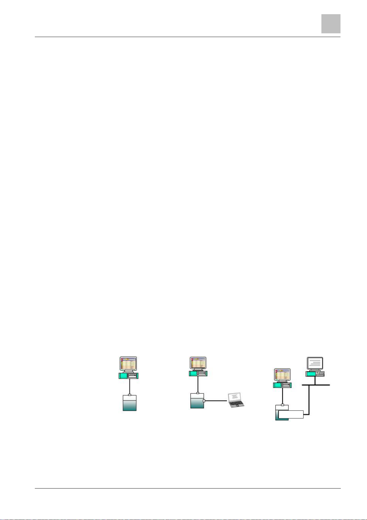
Siemens fire safety and security products are designed to work together. While
there are many occasions where only one product may be used in a facility, when
combined our products create a robust and flexible set of architectural and
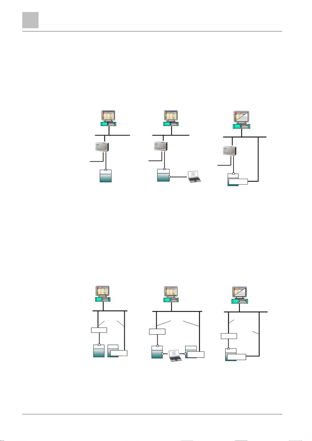
connectivity solutions. The possible combinations of Danger Management Systems
(DMS), network choices, and subsystems used in any given plant are extensive.
However, the time involved with commissioning tasks can be substantial.
With the aim of reducing time spent on configuration, Siemens BT FS has
developed their products so that the DMS and the networks can all be configured
with a single tool called WW8000 Composer.
The networks and subsystems supported by our Danger Management Systems are
always configured in the same way within the Composer environment.
What this document contains
This document includes the configuration procedures for the video subsystems
supported by our DMS8000 products. It discusses in detail how to configure these
systems by hand.
What this document does not contain
Each DMS carries a different set of technical and behavioural characteristics that
interact with the networks and subsystems. These differences typically appear as
additional tabs in the network and subsystem work areas of Composer. However,
since these tabs are always associated with attributes specific to the DMS being
used, they are not discussed in this manual. This information can be found in the
corresponding product manual.
Reference documents are listed in the Resource Information document (see About
this document [➙4]).
1.1 Additional documents
Depending on your level of experience with Composer, and the architectural
solutions available with our products, as well as where you are in the
commissioning process, there are a number of additional documents that you may
find useful. If you need a document that you do not have, you can download it on
the Siemens Intranet.
Please see the following descriptions of relevant additional documents:
lThe Composer WW8000 Technical Manual contains mostly introductory
information for new users of Composer. In addition to general introductory
information, it contains details about several functions and shortcuts that can
be useful for users. This manual is typically included with the documentation
set that comes with each product. The document number is A6V10062401.
lThe Application and Planning guide (A6V10063710) shows the architectural
solutions currently available with the DMS systems, including network and
subsystem connectivity options. These documents are a kind of library of
technical solutions, and are intended primarily as sales tools, but provide an
overview of the relationships within the system that may be useful when
planning a configuration.
lThe product-specific Installation Configuration & Commissioning manual (ICC)
is the necessary complement to this manual for getting a complete view of the
configuration process. Please refer to the latest edition of the following
document:
– MM8000 ICC (A6V10062413)
– MT8001 ICC (A6V10096181)
– MK8000 ICC (A6V10062407)
– NK8000 ICC (A6V10062437)

1Introduction
What's new
8
Building Technologies A6V10359489_a_en
CPS Fire Safety 30.09.2016
lThe Network Connectivity Guide (A6V10359485) contains detailed information
about configuring the networks supported by DMS8000 products.
Reference documents are listed in the Resource Information document (see About
this document [➙4]).
1.2 What's new
Here is the list of modifications for new functions and software improvements.
Section Modifications
Configuring an SPC4000/SPC5000/SPC6000
[➙ 18] Removed limitations about user name display of
duress events with FlexC.

Configuring intrusion control units 2
Configuring a Sintony SI410
9
Building Technologies A6V10359489_a_en
CPS Fire Safety 30.09.2016
2Configuring intrusion control units
This section describes how to configure control units. The list includes:
lSI410
lSPC4000/SPC5000/SPC6000
lCS6 Guarto
lCS4
lCS440
lCZ12
2.1 Configuring a Sintony SI410
The Sintony SI410 is an intrusion detection unit with individual addressing and
access control capability. It can handle detection lines on which
transponder
units
can concentrates
alarm inputs
and
outputs
. Inputs can be operated in groups,
organised in
Rooms
,
Wards
, and
Clusters
.
The physical and logical configuration for the unit is first defined for the hardware
unit set-up by means of a PC tool (
SYLCOM
), and then ported to the Composer
environment using a metafile generated by a special tool, the
Sintony Uploader
,
distributed with the DMS8000 products.
The Sintony SI410 can communicate to DMS8000 systems over a serial line or via
network connection using an internal (SMN36 or SMN42/43) or external (NK8000
or 3rd party) network adapter.
SI420 model
The SI420 model also exists and it is functionally equivalent to the SI410 as far as
the management station functions are concerned. In this document, the name
SI410 is used hereafter to refer to either model.
2.1.1 SI410 connectivity overview
A - Serial connection
SI410 can be connected to DMS8000 over a serial line. The service PC running the
SI410 SYLCOM tool can connect via another serial port or over a LAN link. Note
that the LAN connection requires the SMN36 (or the newer SMN42/43) module or
an external adapter (see the
Network Connectivity Guide
).
DMS8000 connection SYLCOM tool connection (serial) SYLCOM tool connection (LAN)
MM8000 station
MM8000 station MM8000
station Tool
J10
J1
J10
Ethernet
10-base-T
Sylcom
SMN36/42
SI410
SI410
J7
RS232
SAQ18 cable (*)
(*) The small printer
circuit on one end of the
cable is labelled SMQ18.
RS232
SAQ18 cable
RS232
SAQ11
cable
LAN
RS232
SAQ18
cable
SI410 serial connectivity: DMS8000 and Sylcom Tool

2Configuring intrusion control units
Configuring a Sintony SI410
10
Building Technologies A6V10359489_a_en
CPS Fire Safety 30.09.2016
B - Network connection via NK8000
The NK8000 network allows for connecting a SI410 unit using a serial line. The
NK82xx Ethernet Port unit provides an optimised (and possibly encrypted) access
to the LAN (Ethernet 10-Base-T) for DMS8000. NK82xx can also handle local
interactions between the connected subsystems.
The service PC running the SI410 SYLCOM tool can connect via another serial
port or over a LAN link. Note that the LAN connection for the tool requires the
SMN36/42/43 module see the
Network Connectivity Guide
).
MM8000 station MM8000 +
Sylcom
DMS8000 connection SYLCOM tool connection (serial) SYLCOM tool connection (LAN)
MM8000 station
LAN
J10
SI410
LAN
J1
LAN
J10
SI410 SI410 Ethernet
10-base-T
RS232
SAQ11
cable
J7
RS232
SAQ18 cable
+ (crossed)
null-modem
adapter
RS232
SAQ18 cable
+ null-modem RS232 RS232
SAQ18 cable
+ null-modem
Sylcom
SMN36/42
SI410 Network connectivity via NK8000: DMS8000 and Tool
C - Network connection via adapters
The use of serial-to-network adapter permits the LAN connection to DMS8000
using the SI410 serial port.
The internal adapter SMN36/42/43 or an external device (e.g. LANTRONIX
UDS1100) can support the LAN (Ethernet 10-Base-T, 10Kbps) connectivity. The
service PC running the SI410 SYLCOM tool can connect via another serial port or
over a LAN link.
In comparison with the option B, this solution offers no encryption or interaction
capability.
MM8000 station
Links to
MM8000
UDS1100
LAN
J10 RS232
SAQ18+adapter
SMN36/42
SI410 SI410
Sylcom
MM8000 +
Sylcom
LAN
Link to
MM8000
Link to
Sylcom
UDS1100
J1 RS232
SAQ18+adapter
SMN36/42
SI410 Ethernet
10-base-T
DMS8000 connection SYLCOM tool connection (serial) SYLCOM tool connection (LAN)
MM8000 station
LAN
J10
Links to
MM8000
UDS1100
RS232
SAQ18+adapter
SMN36/42
SI410 SI410
J7 J7
RS232
SAQ11
SI410 Network connectivity via adapters: DMS8000 and Tool

Configuring intrusion control units 2
Configuring a Sintony SI410
11
Building Technologies A6V10359489_a_en
CPS Fire Safety 30.09.2016
2.1.2 SI410 connectivity: technical notes
2.1.2.1 SI410 internal options and settings
Serial ports
The SI410 can provide serial connectivity to host computers on the port J1, J7 and
J10 (please refer to SI410 documentation).
Note:
Port
J7
is used for connecting to the Sylcom PC, whereas
J1
or
J10
is used
for DMS8000. In the connection solutions to DMS8000, the J10 port is used when
the Sylcom tool is connected to J7. J1 should instead be used for DMS8000 when
the tool connects over LAN via SMN36/42/43.
Note:
When in serial mode, in the System Node of the SYLCOM tool, please
select the following options:
–Networking mode = J10 (or J1)
–Sending Node = WUD
Network adapters SMN36 and SMN42/43
The SI410 control unit also offers an internal module option for serial to LAN
TCP/IP conversion, namely the SMN36 or SMN42/43 board. This optional module
is installed internally to the control unit’s cabinet and provides a 10-base-T Ethernet
link on RJ-45 connector.
Note that the SMN36/42/43 is the only option that allows network connectivity for
the Sylcom tool.
Note:
The SMN36/42/43 board is internally connected to the SM410 motherboard
with a flat cable.
On the SMN36 circuit board, jumper S1 and S2 must be closed.
On the SMN42/43 circuit board, set the S250 switch to OFF. In addition, in the
DIP-switch set, set the Config switch to ON and all other switches to OFF (namely
Res,Boot,WD,FW-upd, and SI1/2).
In this configuration, the SI410 must be connected to the building network via an
Ethernet Hub or Switch that is compatible with the speed of the SMN36 or
SMN42/43.
SMNxx setup in the Sylcom tool - System page, IP network settings
The SI410 configuration should include some specific parameters for the SMNxx
board. The picture below shows the required options:
lUp/download mode: do not select Mode 0 (first option).
lNetworking Mode:on J1.
lIP LMS: IP address of DMS8000 stand-alone or FEP (NS8014 driver).
lSintony IP address: IP address of SI410 unit.
lIP gateway: if required, enter IP address for the router/gateway that links the
SI410 subnet with the DMS8000 subnet. If not used, set 0.0.0.0 (the default
255.255.255.0 will not work).
lMask IP: enter the required IP mask (typically 255.255.255.0).
lSintony IP Port 2: IP Port number (contact network administration) used by the
DMS8000 driver NS8014 to communicate over Ethernet. This is the TCP port
number that should be configured in Composer (see Configuration procedures

2Configuring intrusion control units
Configuring a Sintony SI410
12
Building Technologies A6V10359489_a_en
CPS Fire Safety 30.09.2016
[➙ 15]).
Note that the Sintony IP port field is used for the Sylcom network link only.
SI410 configuration for network connectivity
Further options required in the Sylcom tool - System page
In order to be able to reset alarms from DMS8000 with no need of unsetting the
Ward, make sure to enable the Clear Al.Mem Full Set option in the System
Properties.
Options required in the Sylcom tool – ARCpage
The Serial Port Protocol must be set, e.g. SUPALARM TCP/IP to enable the
SMNxx card.
2.1.3 Configuration checklist
Verify that you have satisfied the items needed in the first checklist before
proceeding to the configuration checklist that follows.
Items needed for configuration
lThe number of SI410 in the system.
lThe SI410 metafile(s) generated by the Sintony Uploader tool (.INI file).
lIf serial connectivity is used, the SAQ18 cable is required for connecting the
SI410 J10 serial line interface of the SM410 mainboard (to be ordered from the
intrusion product range).
lThe host PC or the NK82xx and the serial line where to connect the SI410. For
connecting NK82xx or PC to the SAQ18 cable, a crossed serial cable is
needed (a DB9/m and a DB9/f connector for NK82xx or two DB9/f connectors
for PC.)
lIf the LAN connectivity is used, the IP address and TCP port of the LAN
communication.
lPlug-ins needed:
– #352001
Note:
Plug
-
ins are installed during the software setup procedure. You can check
that the Plug-ins are actually available using the Composer Plug-in Installer in the
DMS8000 start menu.

Configuring intrusion control units 2
Configuring a Sintony SI410
13
Building Technologies A6V10359489_a_en
CPS Fire Safety 30.09.2016
Configuration overview
1. Generate the SI410 metafile.
2. Add the folder(s) required for identifying the location of the SI410 in the project
structure tree.
3. Add SI410 system node to the new folder.
4. Import the metafile.
5. Link the SI410 to the communication line.
6. Configure the serial or network link options.
7. Repeat the steps above for all the SI410s in the project
2.1.4 Generating the SI410 metafile
Configuration uploading tool
The SI410 physical and logical configuration should be saved into an export file
(metafile) in order to import it into Composer. The metafile is generated by the
Sintony Uploader
tool that is capable of acquiring the configuration data from the
control unit over the serial line.
This tool is one of the utilities available in the DMS8000 products. Refer to the
Installation, Configuration, and Commissioning manuals.
Reference documents are listed in the Resource Information document (see About
this document [➙4]).
Note:
The metafile exported by the SYLCOM program, and used by LMSmodular,
is not valid for the Composer import described here.
Uploading the metafile data
The
SintonyUploader.exe
program is installed along with DMS8000 software in the
Utilities folder and allows for an easy generation of the required metafile. Proceed
as follows:
1. Connect the SI410.
a) Direct Serial connection to the PC with the uploading software.
Configure the serial port in the unit to handle a host serial link on the J10 port
(this link is used for both the NK82xx and the upload tool connection).
Connect the SI410 port to any COM port of the PC where the Sintony Uploader
is available. Use the SAQ18 cable (refer to the SI410 documentation) and a
crossed serial cable with two DB9/f connectors.
b) LAN IP connection to the PC with the uploading software.
You need the LAN adapter (SMNxx) option installed (see SI410 internal options
and settings [➙11]). The IP connection will be based on the SI410 IP address
and the IP Port 2. From the DMS8000 PC, the SI410 unit should be reachable
using the ping command.
Note: Given that only one TCP port is available on SI410 for external hosts, the
LAN connection of the Sintony Uploader makes use of the same port as the
NS8014 DMS8000 driver. This implies that you need to stop the DMS8000
server software before connecting the Sintony Uploader.
c) Connection via NK82xx
Preliminary steps:
- Configure the serial port to handle a host serial link on the J10 port (this link is
used for both the NK82xx and the upload tool connection).
- Configure the SI410 node in Composer and link it to the NK8000 COM port

2Configuring intrusion control units
Configuring a Sintony SI410
14
Building Technologies A6V10359489_a_en
CPS Fire Safety 30.09.2016
(see Configuration procedures [➙15]).
- Download the configuration on the NK8000 unit (see the
Network Connectivity
Guide
).
- Connect the SI410 port to the COM port of the appropriately configured
NK82xx port.
2. Launch SintonyUploader.exe.
aThe software guides you through the following steps.
3. Select the connection type: direct serial, LAN or NK82xx.
a) Serial connection: click Next and then Auto Detect button.
aThe software automatically detects the correct COM port.
4. LAN IP Connection: enter the Sintony IP address and port (IP Port 2).
Connection via NK82xx: enter the NK82xx IP address.
Note: If this step fails, check the physical connection and try again.
Sintony Uploader: selecting the connection type
Sintony Uploader: auto-detecting the COM port
5. At this point, pressNext and let the Read Data page show up.

Configuring intrusion control units 2
Configuring a Sintony SI410
15
Building Technologies A6V10359489_a_en
CPS Fire Safety 30.09.2016
6. Then press the Start button.
Note: In case of errors, check the SI410 firmware release (compare with latest
requirements in the DMS8000 product Release Notes).
aThe software starts communicating with the SI410 and acquiring the
configuration data over the serial line. An item list and a progress bar show
the activities and the uploading results.
Sintony Uploader: uploading the configuration
7. When the upload process has completed, a success message appears.
Click OK to acknowledge it.
8. Save the uploaded data.
You have now to select the file name and destination folder of the metafile. Use
the browsing button to open the navigation windows.
Sintony Uploader: saving the configuration
9. Finally, press Next and then Finish to terminate the program.
2.1.5 Configuration procedures
Adding the intrusion system folder
1. In the left-hand bar, click the Generic Template icon .
aA new node is added to the project structure.
2. Select the new folder and name it in the Description field of the Node tab.

2Configuring intrusion control units
Configuring a Sintony SI410
16
Building Technologies A6V10359489_a_en
CPS Fire Safety 30.09.2016
Adding the intrusion system node
1. Select the new folder.
2. In the left-hand bar, select the Intrusion folder icon .
3. In the menu that appears, select the appropriate icon to add a new intrusion
system node.
aA new node is added to the project structure.
Note:
You can customise the default name of the new node typing in a new name
in the Description field of the Node tab, but do not customise it now since it will be
renamed during the metafile import.
Adding a new SI410 node
Importing the SI410 metafile
1. Select the SI410 node.
2. Select Tools > Import in the Composer menu to start SI410 import.
3. The software presents a browsing window to search for the file to import (the
INI file is expected, see Generating the SI410 metafile [➙13]).
4. Select the import file from the file selection window and click Open.
aIn a few moments, the SI410 structure is imported, and the node is represented
in the Composer tree.
Note:
The node is renamed to match the metafile name. To customise the name,
click the node text, type in a new name, and press ENTER.
Note:
After the import procedure, by selecting the
Import
tab, a report page
displays. It contains the detailed logs of the latest import procedure, including any
added or removed objects.
Linking the SI410 to the Communication network (NK8000)
To link the SI410 node to the NK82xx node, do the following:

Configuring intrusion control units 2
Configuring a Sintony SI410
17
Building Technologies A6V10359489_a_en
CPS Fire Safety 30.09.2016
1. Expand the network folders until you reach the node that represents the
NK8000 network node physically connected to the SI410.
2. Select the SI410 node.
3. Drag and drop the SI410 Sintony node to the serial port of the NK82xx node.
4. In the newly created link, configure the communication Baud Rate.
Note: Composer helps you in recognising a valid link by showing a shortcut Link
icon instead of the circle No-link icon .
Linking SI410 to NK82xx
Linking the SI410 to the Communication network (MM8000/MK8000)
To link the SI410 node to the MM8000/MK8000, do the following:
1. Expand the system station folders (Stand-alone or FEP) until you reach the
node that represents the NS8014 driver.
2. Select the NS8014 SI410 Driver node.
Note: If this driver is not present, you can add it to the Channels by clicking the
corresponding icon on the left toolbar.
3. Drag and drop the SI410 node to the driver.
aA new node appears in the tree under the driver representing the link.
Configuring the serial or network link (MM8000/MK8000)
In the newly created link, configure the communication options.
1. Under the NS8014 SI410 Driver node, select the link node.
2. Select the Node tab.
3. Configure the communication options:
– In case of serial link (see Figure
Setting the serial communication options
),
set the Serial Port, the Baud Rate and the bit-packet options (Parity,Data,
and Stop bits) that the DMS8000 station uses to connect top the SI410 unit.

2Configuring intrusion control units
Configuring an SPC4000/SPC5000/SPC6000
18
Building Technologies A6V10359489_a_en
CPS Fire Safety 30.09.2016
– In case of network link (see Figure
Setting the network communication
options
), set the IP address of the SI410 control unit and the TCP Port
Number used in the network communication.
Setting the serial communication options
Setting the network communication options
2.2 Configuring an SPC4000/SPC5000/SPC6000
The SPC4000, SPC5000 and SPC6000 are intrusion detection units belonging to
the SPC series. They can support both wired and wireless intrusion devices (true
hybrid controller) and a LAN interface possibly integrated by additional
communications modules (PSTN/GSM/RF). Starting from SPC V3.1 all the SPC
model types support Ethernet connection.
Intrusion inputs can be operated in groups, organised in
Areas
and
Zones
. Exact
limits depend on the SPC model.
The SPC units can communicate to an external system over a network TCP/IP
connection. The MM8000/MK8000 systems can support the FlexC protocol
(starting from SPC V3.6) and the EDP protocol (Europlex Datagram Protocol). The
two protocols are managed by 2 different drivers. The SPC panel can be linked to 1
driver only, but you can create both drivers in the SPC project with a single license.
The FlexC protocol is an encrypted protocol which provides more information and
commands than the EDP protocol, and offers a redundancy mechanism which
supports up to 9 backup physical paths between the SPC panel and the
management station.

Configuring intrusion control units 2
Configuring an SPC4000/SPC5000/SPC6000
19
Building Technologies A6V10359489_a_en
CPS Fire Safety 30.09.2016
The support of the FlexC protocol by MM8000/MK8000 systems has the following
restriction:
lThe redundancy mechanism is not supported.
lOnly the fixed key encryption method is supported (
AutoEncryption
is not
supported).
If you use the FlexC protocol, take note also of the following:
lYou can reset fault events (like
Warning Fault
,
Hold Up Fault
, and
Detector
Fault
) only if the grade of the panel is set to
Unrestricted
or
Grade 2.
You can use the
Restore Alarm
command of the SPC configuration tool
instead.
2.2.1 Local SPC settings: technical notes
The SPC physical and logical configuration is first defined for the hardware unit set-
up using the SPC configuration tool (SPC Pro or the web-based tool) and then
ported to the Composer environment using an export file (SigNET X Configuration
File). The configuration instructions, which are relating to the SPC Pro interface,
are different for the FlexC and the EDP protocol.
Note:
The SPC configuration tool is a web application that works with an Internet
browser. The most common browser, Internet Explorer (IE), requires however a
special setting: in Tools > Internet Options > Advanced tab, in the option list,
search for the Security options and enable Do not save encrypted pages to disk.
FlexC protocol configuration
1. Start the SPC configuration tool in Full Engineer mode.
2. Add an SPC panel.
3. Select the SPC panel and click Configure.
4. Select Communications > FlexC and click Add Single Path ATS (
Alarm
Transmission System
). Note the following parameters:
–SPT Account Code: ID of the panel.
–RCT ID: must match the NS8021 driver setting [➙21].
–RCT URL or IP Address: must match the IP address of the management
station.
–RCT TCP Port: must match the NS8021 driver setting [➙21].
5. Click the ATS you created and check the values of the following parameters in
the ATS Profiles section:
–Event Profile: must be Default Events (default value).
–Command Profile: must be Default Commands (default value).
6. Edit the ATP (
Alarm Transmission Path
) in the ATP list, then click Advanced
ATP Settings and configure the encryption mode in the Encryption section:
–Encryption Key Mode: must be Fixed Encryption.
–Encryption key: type the encryption key (64 hexadecimal digits are
required).
7. Select Panel Settings > System Settings > Timers and configure the following
parameters:
–Dialler delay: must be 0; otherwise a delay occurs before alarms are
transmitted to the management station.

2Configuring intrusion control units
Configuring an SPC4000/SPC5000/SPC6000
20
Building Technologies A6V10359489_a_en
CPS Fire Safety 30.09.2016
–Time Sync Limit: suggested value is 120 seconds (max value is 999).The
time synchronization command is only accepted by the panel if the new
time and actual time of the control panel are outside of the defined time
interval; otherwise the command will be ignored.
8. Select Panel Settings > System Settings > All Zones and check for the Local
attribute of each zone: the Local attribute must not be selected.
9. Save and export the SPC configuration file.
aSPC Pro exports a
[file_name].cfg
configuration file.
aThe web tool exports a
[file_name]_cfg
file. You need to manually rename the
file
[file_name].cfg
(note the
.cfg
extension.)
EDP protocol configuration
1. Start the SPC configuration tool in Full Engineer mode.
2. Add an SPC panel.
3. Select the SPC panel and click Configure.
4. Select Communications > EDP Settings and add an EDP receiver. Note the
following parameters:
–Receiver ID: must match the NS8013 driver setting [➙21].
–Receiver IP Address: must match the IP address of the management
station.
–Protocol version: must be
Version 2
(click the EDP receiver to edit this
parameter).
–Event Timeout: must be higher than 0.
5. Click the EDP receiver and click Advanced. Configure the following
parameters:
–Commands Enable: must be selected.
– Select the Network Enable check box and configure the Network Protocol:
select TCP/IP or UDP/IP.
–Receiver Port: must match the NS8013 driver setting [➙21].
–Always Connected: must be selected.
–Panel Master: must be selected for TCP/IP.
–Polling Interval: keep the default value 10.
–Polling Trigger: keep the default value 10.
–Primary Receiver: must be selected.
–Requeue Events: must be selected.
6. Click the Filter button. In the Event Filter list that displays, select all check
boxes except Early / Late and Zone States (to prevent slowing the system).
7. Select Panel Settings > System Settings > Timers and configure the following
parameters:
–Dialler delay: must be 0; otherwise a delay occurs before alarms are
transmitted to the management station.
–Time Sync Limit: suggested value is 120 seconds (max value is 999).The
time synchronization command via EDP is only accepted by the panel if the
new time and actual time of the control panel are outside of the defined
time interval; otherwise the command will be ignored.
Other manuals for DMS8000
6
This manual suits for next models
9
Table of contents
Other Siemens Firefighting Equipment manuals
Popular Firefighting Equipment manuals by other brands

Task Force Tips
Task Force Tips TORNADO manual

POK
POK CRIQUET user manual

Hochiki
Hochiki FirePro Xtinguish Installation and operation manual

Trident
Trident Foamate 1.0 Installation & operation guide

Task Force Tips
Task Force Tips EDUCTOR 125 Series Instructions for installation, operation and maintenance

Tyco
Tyco B-1 manual