Leadshine Technology Co. DCS303 User manual

User sManual
For
DCS303
DigitalBrushDC ServoDriver
Revision 1.0
2009All RightsReserved
Attention:Pleaseread thismanual carefullybeforeusingthe driver!
3/F, Block 2, NanyouTiananIndustrialPark, NanshanDist, Shenzhen, China
Tel: (86)755-26434369 Fax: (86)755-26402718
URL: www.leadshine.com E-Mail: sales@leadshine.com
Thecontentinthismanualhasbeencarefullypreparedandisbelievedtobeaccurate,
butnoresponsibilityisassumedforinaccuracies.
Leadshinereservestherighttomakechangeswithoutfurthernotice toanyproducts
hereintoimprovereliability,functionordesign.Leadshinedoesnotassumeany
liabilityarisingoutoftheapplicationoruseofanyproductorcircuitdescribed
herein;neitherdoesit conveyanylicenseunderitspatentrightsofothers.
Leadshine sgeneralpolicydoesnotrecommendtheuseofitsproductsinlife
supportoraircraftapplicationswhereinafailureormalfunction oftheproductmay
directlythreatenlifeorinjury.AccordingtoLeadshine stermsandconditionsof
sales,theuserofLeadshine sproductsinlifesupportoraircraftapplications
assumesall risksofsuchuseandindemnifiesLeadshineagainstall damages.
©2009byLeadshineTechnologyCompanyLimited.
AllRightsReserved

Contents
Tel: (86)755-26434369IWebsite: www.leadshine.com
TableofContents
1. Introduction, FeaturesandApplications..................................................................1
Introduction..........................................................................................................1
Features................................................................................................................1
Applications.........................................................................................................2
2. SpecificationsandOperating Environment.............................................................2
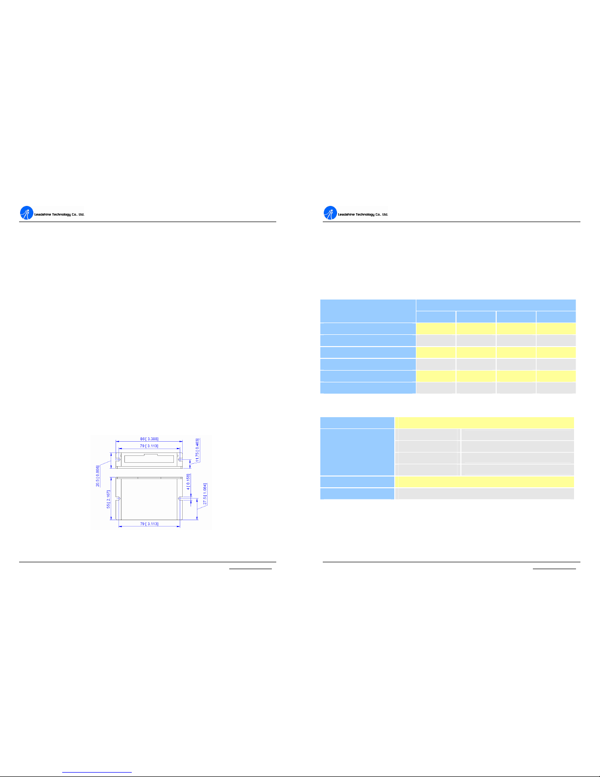
MechanicalSpecifications....................................................................................2
EliminationofHeat..............................................................................................3
ElectricalSpecifications.......................................................................................3
OperatingEnvironmentandParameters...............................................................3
3. Connections.............................................................................................................4
ConnectorConfiguration......................................................................................4
Generalinformation....................................................................................4
MoreaboutPUL/DIR/ENASignals............................................................5
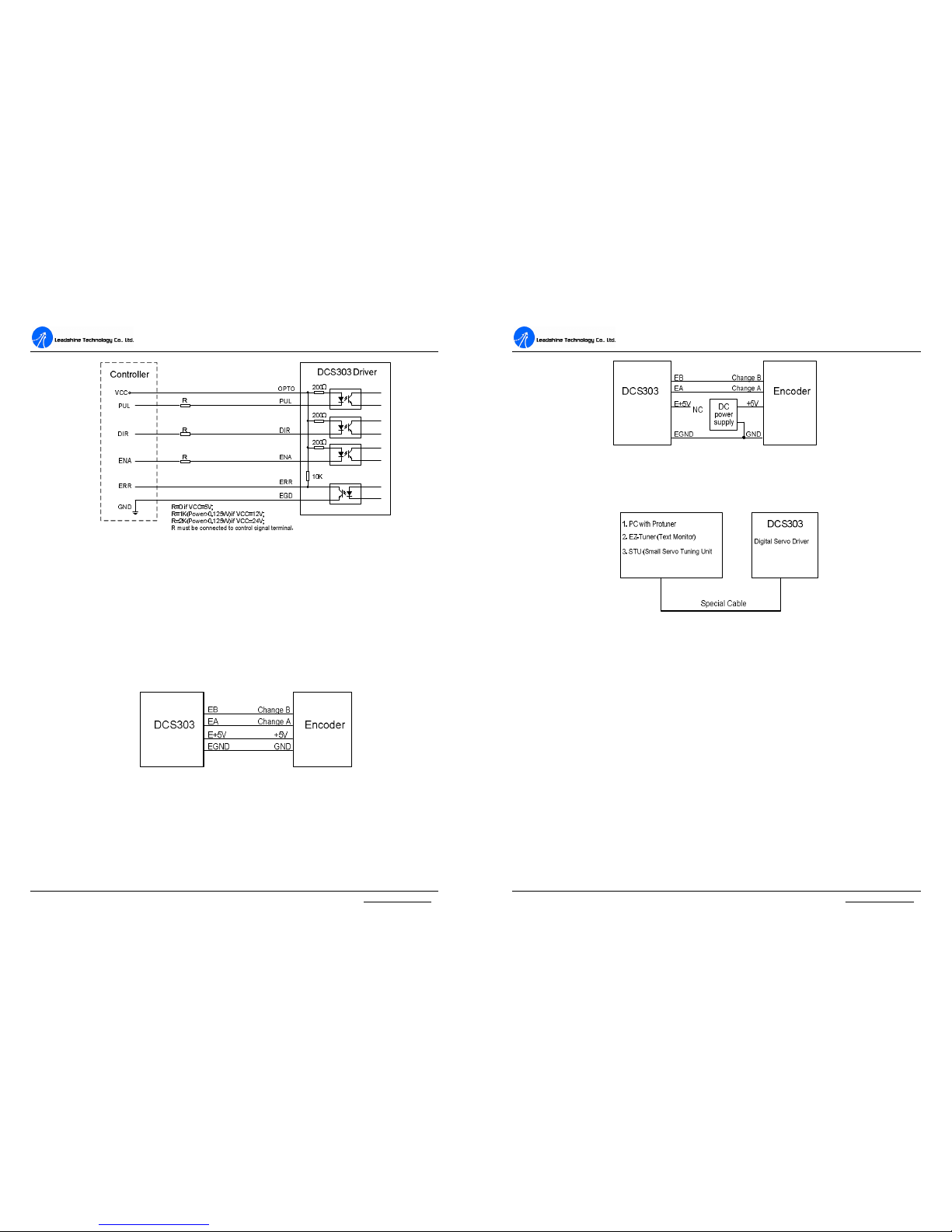
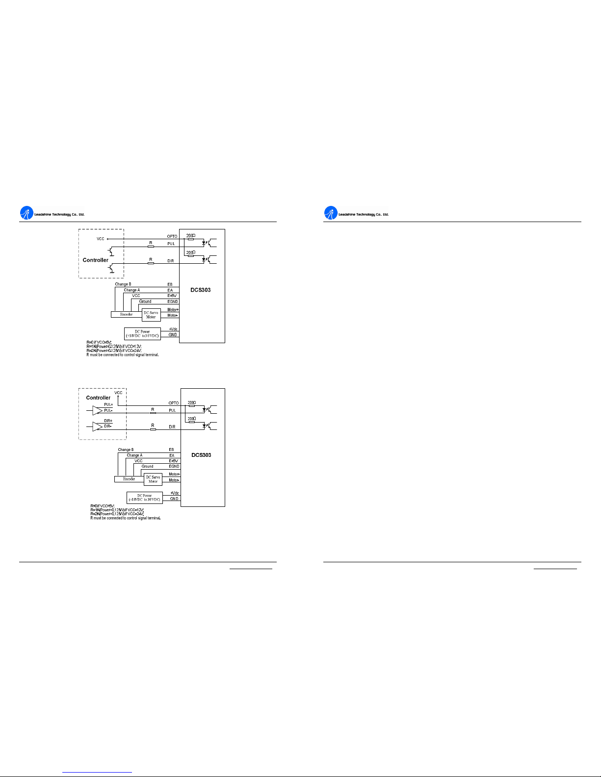
ControlSignalConnections..................................................................................5
EncoderConnections............................................................................................6
RS232 Interface Connection.................................................................................7
TypicalConnections.............................................................................................7
4. ServoSetup.............................................................................................................9
Install Encoder......................................................................................................9
PreparePowerSupply..........................................................................................9
RegulatedorUnregulatedPowerSupply....................................................9
SelectingSupplyVoltage.............................................................................9
PrepareController..............................................................................................10
SystemConnectionsandNoisePrevention........................................................10
WireGauge................................................................................................10
CableRouting............................................................................................11
Contents
Tel: (86)755-26434369II Website: www.leadshine.com
Twisted Wires............................................................................................11
CableShielding.........................................................................................11
SystemGrounding.....................................................................................11
PowerSupplyConnection.........................................................................12
5. Tuningtheservo....................................................................................................12
Testingtheservo.................................................................................................12
TuningtheServo................................................................................................13
6. PCwindowbasedTuningUsingProTuner...........................................................15
Introduction........................................................................................................15
SoftwareInstallation..........................................................................................15
RS232 Interface Connection..............................................................................19
Testingtheservo.................................................................................................20
SoftwareIntroduction.........................................................................................21
ProTunerMain Window............................................................................21
ComConfig Window................................................................................22
ServoTuning......................................................................................................30
Position LoopIntroduction.......................................................................30
Position aroundVelocity...........................................................................31
Position aroundTorque.............................................................................31
Position LoopTuning................................................................................32
7. UsingTips.............................................................................................................40
SequenceChartofControlSignals....................................................................40
ProtectionFunctions...........................................................................................40
Over-currentProtection.............................................................................41
Over-voltageProtection............................................................................41
PhaseErrorProtection...............................................................................41
EncoderErrorProtection...........................................................................41
Position FollowingErrorProtection.........................................................41
ProtectionIndications................................................................................42

Contents
Tel: (86)755-26434369III Website: www.leadshine.com
ChangingDefault MotorDirection....................................................................42
MaximumPulseInputFrequency......................................................................42
APPENDIX...............................................................................................................43
TWELVEMONTHLIMITEDWARRANTY...................................................43
EXCLUSIONS...................................................................................................43
OBTAINING WARRANTYSERVICE.............................................................43
WARRANTYLIMITATIONS............................................................................43
SHIPPING FAILEDPRODUCT........................................................................44
ContactUs.................................................................................................................45
D
DC
CS
S3
30
03
3
D
Di
ig
gi
it
ta
al
l
D
DC
C
S
Se
er
rv
vo
o
D
Dr
ri
iv
ve
er
r
M
Ma
an
nu
ua
al
l
R
Re
ev
v1
1.
.0
0
Tel: (86)755-264343691Website: www.leadshine.com
1. Introduction, Features and Applications
Introduction
TheDCS303 isadigitalDCservo driverdevelopedwithDSPandhighefficient
MOSFETtechnologies.Inposition control,it seasyfortheenduserstochange
steppingdriverstotheDCS303 withoutchangingcontrolsystems,becauseitsinput
commandisPUL/DIRsignal,whichiscompatiblewiththatofsteppingdrivers.In
lowpowermotioncontrolapplications,performancesofDCservosystemsusing the
DCS303 arebetterthanthoseofdigitalACservosystemsinvelocity,precision,
stability,oratleastasgoodasthoseofdigitalACservosystems.However,thecost
oftheDCS303 staysattheprice lineofsteppingdriver,namelyfarlowerthanthose
ofACservo drivers.
TheDCS303 isamicrosizebrushDCservodrive.Itisanidealchoice forthose
applicationsinwhichthemountingspace forthedriverislimitedandhigheroutput
powerisnotnecessary.
TheDCS303 isveryeasytotuneand all parametersarevisible.HandheldandPC
basedtuningtools,includingProTuner(Windowsbasedsetupsoftware)and STU
(Small servotuningunit)canmeetdifferenttuning environmentsorrequirements.
Features
lInputVoltage:18-30VDC
lOutputCurrent: 3 A(Cont.), 15A(Peak), Powerrange:5-90W.
lBasedonDSPcontroltechnologyand highsmoothservocontrolalgorithm.
lHandheldandPCbasedtuningtools, includingProTunerand STU.
lFeedbackresolution ×4 encoderlinecount.
lPosition Followingerrorlockrangeadjustable
lPosition errorcan beeliminatedto1 count, andvelocityerrorcanbeeliminated

D
DC
CS
S3
30
03
3
D
Di
ig
gi
it
ta
al
l
D
DC
C
S
Se
er
rv
vo
o
D
Dr
ri
iv
ve
er
r
M
Ma
an
nu
ua
al
l
R
Re
ev
v1
1.
.0
0
Tel: (86)755-264343692Website: www.leadshine.com
totheDesiredVelocity* ±0.3%
lElectronicgearratiofrom1/255 to255
lBuilt-inmotioncontrollerforself-testwithtrapezoidalvelocityprofile
lSupportPUL/DIRcontrolsignals
lOpto-isolatedinputs, supportsingle-endedsignals
l10 latesterrorsself-recordfunction
lOver-current,over-voltage,phaseerror,encodererror,positionfollowingerror
protections
lSmall size, surface-mounttechnology
Applications
Suitableforawiderangeofequipmentsandinstrumentssuchasminitype
engravingmachines,inkjetprinters,etc.Itperformsbetterintheapplicationsrequire
lownoise,highvelocity,highprecision andhighreliability.
2. Specifications andOperatingEnvironment
MechanicalSpecifications (unit:mm[inch])
Figure2-1:Mechanicalspecifications
D
DC
CS
S3
30
03
3
D
Di
ig
gi
it
ta
al
l
D
DC
C
S
Se
er
rv
vo
o
D
Dr
ri
iv
ve
er
r
M
Ma
an
nu
ua
al
l
R
Re
ev
v1
1.
.0
0
Tel: (86)755-264343693Website: www.leadshine.com
EliminationofHeat
lDriver sreliableworkingtemperatureshouldbe<70 [158 ],and motor
workingtemperatureshouldbe<80 [176 ];
lItisrecommendedtomountthedriververticallytomaximizeheatsinkarea.
ElectricalSpecifications(Tj =25 /77℉)
DCS303
Parameters Min. Typical Max. Unit
Peakoutputcurrent 0 - 15 A
Supplyvoltage +18 +24 +30 VDC
Logicsignalcurrent 7 10 15 mA
Pulseinputfrequency 0 - 200 kHz
Isolationresistance 500 MΩ
Currentprovidedtoencoder 50 mA
OperatingEnvironmentand Parameters
Cooling Natural coolingorforcedcooling
Environment Avoiddust, oil fog andcorrosivegases
AmbientTemperature
0 ºC–50 ºC
Humidity 40 –95%RH
OperatingEnvironment
Vibration 5.9m/s2Max
StorageTemperature -20 ºC –+65 ºC
Weight Approx. 110 g(3.88oz)

D
DC
CS
S3
30
03
3
D
Di
ig
gi
it
ta
al
l
D
DC
C
S
Se
er
rv
vo
o
D
Dr
ri
iv
ve
er
r
M
Ma
an
nu
ua
al
l
R
Re
ev
v1
1.
.0
0
Tel: (86)755-264343694Website: www.leadshine.com
3. Connections
ConnectorConfiguration
Generalinformation
Control SignalConnector
Pin Signal
Description I/O
1 PUL Pulsecontrolsignal I
2 DIR Directioncontrolsignal I
3 OPTO +5VOpto-isolatedpowerinput I
4 ENA Enablecontrol signal, canbeusedtoclearpositionfollowingerror I
5 ERR Erroroutputsignal,HIGH indicatesnormal, LOWindicatesfault. O
6 EGD Opto-isolatedGND, useforreferencewhenusingERR GND
EncoderSignalConnector
Pin Signal
Description I/O
1 EB EncoderchannelBinput. I
2 EA EncoderchannelAinput. I
3 E+5V
Positivepoleoftheauxiliarypowersupply(50mA(Max)). O
4 EGND
Ground oftheauxiliarypowersupply. GND
PowerConnector
Pin Signal
Description I/O
1 Motor+
Motorpositiveconnection. O
2 Motor-
Motornegativeconnection. O
3 +Vdc +18 TO30VDCpowerinput. I
4 GND PowerGround. GND
RS232 CommunicationConnector
Pin Signal
Description I/O
1 +5V +5VpoweronlyforSTU. O
2 TxD RS232transmit. O
3 GND Ground. GND
4 RxD RS232receive. I
D
DC
CS
S3
30
03
3
D
Di
ig
gi
it
ta
al
l
D
DC
C
S
Se
er
rv
vo
o
D
Dr
ri
iv
ve
er
r
M
Ma
an
nu
ua
al
l
R
Re
ev
v1
1.
.0
0
Tel: (86)755-264343695Website: www.leadshine.com
MoreaboutPUL/DIR/ENA Signals
PinFunction Details
PUL
Pulsesignal: Thisinputrepresentspulsesignal;4-5VwhenPUL-HIGH,
0-0.5VwhenPUL-LOW.Forreliableresponse,pulsewidthshouldbelonger
than2.5μs.Seriesconnectresistorsforcurrent-limitingwhenusing +12Vor
+24Vcontrol signals(OPTO). ThesameasDIRandENAsignals.
DIR
DIRsignal: ThissignalhasLOW/HIGH voltagelevels,4-5Vwhen
DIR-HIGH,0-0.5VwhenDIR-LOW.Forreliablemotion response,DIR
signalshouldbeaheadofPULsignal by5μsatleast. Pleasenotethatmotion
direction isalsorelatedtomotor-driverwiringsandencoderfeedbackA/B
phasesignals.Exchangingtheconnectionsoftwowiresofthemotortothe
driverandA/Bphasesignalsofencoderwillreversemotiondirection.
ENA
Enablesignal: Thissignalisusedforenabling/disablingthedriver.High
level(NPNcontrolsignal,PNPand Differentialcontrolsignalsareonthe
contrary,namelyLowlevelforenabling.)forenablingthedriverand low
levelfordisablingthedriver. Usuallyleft UNCONNECTED (ENABLED).
ERR
Errorsignal: Thispinwill bepulledtoLOWlevel(referenceto EGD)when
drivergoesintofaultystatus.Thereisa10Kresistorconnectedbetween
ERR and OPTO.Pleaserefertofigure2inControlSignalConnectionsfor
moredetails.
ControlSignalConnections
TheDCS303 has3opticallyisolatedlogicinputstoacceptcontrolsignals.These
inputsareisolatedtominimizeoreliminateelectricalnoisescoupledontothe
controlsignals. Inthefollowingfigure,connectionstoopen-collectorareillustrated.
ERR signalcanbeusedforerrordetectingandhasthesamereference (GND)with
PUL, DIRandENAsignal.

D
DC
CS
S3
30
03
3
D
Di
ig
gi
it
ta
al
l
D
DC
C
S
Se
er
rv
vo
o
D
Dr
ri
iv
ve
er
r
M
Ma
an
nu
ua
al
l
R
Re
ev
v1
1.
.0
0
Tel: (86)755-264343696Website: www.leadshine.com
Figure3-1:Connectionstoopen-collectorcontrolsignal(common-anode)
EncoderConnections
If theencoderdrainsless than50mA,theDCS303 cansupplytheencoderdirectly,
and connectit asFigure3-2. If theencoderdrainsmorethan50mA,useanexternal
DCsupplyand connectitasFigure3-3. Notethattwisted-pairshieldedcabling
providesthebestimmunityinelectricallynoisyenvironments.
Figure3-2:TheDCS303 suppliestheencoderdirectly
D
DC
CS
S3
30
03
3
D
Di
ig
gi
it
ta
al
l
D
DC
C
S
Se
er
rv
vo
o
D
Dr
ri
iv
ve
er
r
M
Ma
an
nu
ua
al
l
R
Re
ev
v1
1.
.0
0
Tel: (86)755-264343697Website: www.leadshine.com
Figure3-3:UsingexternalDCpowersupplytosupplytheencoder
RS232 Interface Connection
Figure3-4:RS232 interfaceconnection
TypicalConnections
TwotypicalconnectionsoftheDCS303 areshown asFigure3-5, 3-6. Pleaseconsult
“ControlSignalConnections”and “EncoderConnections”formoreinformation
aboutcontrollerand encoderconnections.

D
DC
CS
S3
30
03
3
D
Di
ig
gi
it
ta
al
l
D
DC
C
S
Se
er
rv
vo
o
D
Dr
ri
iv
ve
er
r
M
Ma
an
nu
ua
al
l
R
Re
ev
v1
1.
.0
0
Tel: (86)755-264343698Website: www.leadshine.com
Figure3-5:Typical connection(Open-collectorcontrolsignal.)
Figure3-6:Typical connection(Differential controlsignal)
D
DC
CS
S3
30
03
3
D
Di
ig
gi
it
ta
al
l
D
DC
C
S
Se
er
rv
vo
o
D
Dr
ri
iv
ve
er
r
M
Ma
an
nu
ua
al
l
R
Re
ev
v1
1.
.0
0
Tel: (86)755-264343699Website: www.leadshine.com
4. ServoSetup
Beforeyoustarttheservo,youcanfollowthebelowsteps.
InstallEncoder
If yourmotorhasnoencoder,youmusthaveanencoder(morethan200 lines)
properlymountedonthemotorbeforeyou start.Andpleaseassembletheencoder
according toitsfactorymanual.Pleaseuseshieldedcablesand separateencoder
signalcablefrominterferencesources,suchasmotorwiresandpowerwiresatleast
5 cm.
PreparePowerSupply
RegulatedorUnregulatedPower Supply
Bothregulatedandunregulatedpowersuppliescanbeusedtosupplythedriver.
However,unregulatedpowersuppliesarepreferredduetotheirabilitytowithstand
currentsurge.Ifregulatedpowersupplies(suchasmostswitchingsupplies.)are
indeedused,it isimportanttohavelargecurrentoutputrating toavoidproblems
likecurrentclamp,forexampleusing4Asupplyfor3Amotor-driveroperation.On
theotherhand,ifunregulatedsupplyisused,onemayuseapowersupplyoflower
currentratingthanthatofmotor(typically50%~70%ofmotorcurrent). Thereason
isthatthedriverdrawscurrentfromthepowersupplycapacitoroftheunregulated
supplyonlyduringtheON durationofthePWMcycle,butnotduringtheOFF
duration.Therefore,theaveragecurrentwithdrawnfrompowersupplyis
considerablylessthanmotorcurrent.Forexample,two3Amotorscanbewell
suppliedbyonepowersupplyof4Arating.
Selecting Supply Voltage
TheDCS303 canactuallyoperatewithin+18Vto+30VDC,including powerinput

D
DC
CS
S3
30
03
3
D
Di
ig
gi
it
ta
al
l
D
DC
C
S
Se
er
rv
vo
o
D
Dr
ri
iv
ve
er
r
M
Ma
an
nu
ua
al
l
R
Re
ev
v1
1.
.0
0
Tel: (86)755-2643436910 Website: www.leadshine.com
fluctuation and backEMFvoltagegeneratedbymotorcoilsduring motorshaft
deceleration.Theratedvoltageofthemotorisanimportantparameterwhen
selecting supplyvoltage.Generallyspeaking,do notuseapowersupplyvoltage
morethan5voltsoftheratedvoltageofthemotor.Highervoltagemaycausebigger
motorvibrationatlowerspeed,andit mayalsocauseover-voltageprotectionor
evendriverdamage.
PrepareController
Prepareacontrollerwithpulseanddirectionsignals.However,theDCS303 hasa
built-inmotioncontrollerforself-testandServoTuning.Thebuilt-inmotion
controllercangeneratecontrolsignalwithtrapezoidalvelocityprofile.
SystemConnectionsand NoisePrevention
Afterfinishingtheabovesteps,youcanconnectyourservosystem. Beforeyoustart,
makesurethatthepowerisoff.Connectyoursystemaccordingtoconnection
diagramsbefore, andpayattentiontothefollowing tipswhenwiring.
Wire Gauge
Thesmallerwirediameter(lowergauge),thehigherimpedance.Higherimpedance
wirewillbroadcastmorenoisethanlowerimpedance wire.Therefore,when
selectingthewiregauge,itispreferabletoselectlowergauge(i.e.largerdiameter)
wire.Thisrecommendationbecomesmorecriticalasthecablelengthincreases.Use
thefollowing tabletoselecttheappropriatewiresizetouseinyourapplication.
Current(A) Minimumwiresize(AWG)
10 #20
15 #18
20 #16
D
DC
CS
S3
30
03
3
D
Di
ig
gi
it
ta
al
l
D
DC
C
S
Se
er
rv
vo
o
D
Dr
ri
iv
ve
er
r
M
Ma
an
nu
ua
al
l
R
Re
ev
v1
1.
.0
0
Tel: (86)755-2643436911 Website: www.leadshine.com
CableRouting
All contentsensitivesignalwiresshouldberoutedasfarawayfrommotorpower
wiresanddriverpowerwiresaspossible.Motorpowerand driverpowerwiresare
majorsourcesofnoiseandcaneasilycorruptanearbysignal.Thisissuebecomes
increasinglyimportantwithlongermotorpoweranddriverpowerwireslengths.
TwistedWires
Twistedwireseffectivelyincreasingnoiseimmunity.Thesuccessivetwistseliminate
noisetransientsalongthelengthofthecable.Bothsignalcablesandpowercables
shouldbeofthetwistedandshieldedtype.Differentialsignalwiresshouldbe
twistedasapair.Thecombinationoftwistedpairwiresandadifferentialsignal
significantlyaddstonoiseimmunity.Powerwiresshouldbetwistedasagroup
alongwiththeground(orchassis)wire, ifavailable.
CableShielding
All signalwiresshouldbebundledandshieldedseparatelyfromdriverpowerand
motorpowerwires.Powerwiresshouldalsobebundledand shielded.When
groundingashield,therule-of-thumbistodosoatthe ‘source ofpowerwhile
leavingtheothershieldendopen.Forexample,inthecaseofmotorpowerwires,
thiswouldbethedriveside.Ideally,twistedpairsshouldbeindividuallyshielded
andisolatedfromtheoutershield,whichencompassesall wireswithinthecable.
However,since thistypeofstringentshieldingpracticeisoftennotrequired,typical
cablesdonotprovideisolationbetweeninnerandoutershields.
SystemGrounding
Goodgroundingpracticeshelpreduce themajorityofnoisepresentinasystem.All
common groundswithinanisolatedsystemshouldbetiedtoPE(protectiveearth)
througha ‘SINGLE lowresistance point.AvoidingrepetitivelinkstoPEcreating

D
DC
CS
S3
30
03
3
D
Di
ig
gi
it
ta
al
l
D
DC
C
S
Se
er
rv
vo
o
D
Dr
ri
iv
ve
er
r
M
Ma
an
nu
ua
al
l
R
Re
ev
v1
1.
.0
0
Tel: (86)755-2643436912 Website: www.leadshine.com
groundloops,whichareafrequentsource ofnoise.Centralpointgroundingshould
alsobeappliedtocableshielding;shieldsshouldbeopenononeendandgrounded
ontheother.Closeattentionshouldalsobegiventochassiswires.Forexample,
motorsaretypicallysuppliedwithachassiswire.Ifthischassiswireisconnectedto
PE,butthemotorchassisitselfisattachedtothemachineframe,whichisalso
connectedtoPE,agroundloopwillbecreated.Wiresusedforgroundingshouldbe
ofaheavygaugeandasshortaspossible.Unusedwiringshouldalsobegrounded
whensafetodososincewiresleftfloatingcanactaslargeantennas,which
contributetoEMI.
Power Supply Connection
NEVER connectpowerandgroundinthewrongdirection,becauseit will damage
theDCS303 driver.ThedistancebetweentheDCpowersupplyofthedriveandthe
driveitselfshouldbeasshortaspossiblesincethecablebetweenthetwoisasource
ofnoise.Whenthepowersupplylinesarelongerthan50 cm,a1000µF/36V
electrolyticcapacitorshouldbeconnectedbetweentheterminal “GND”and the
terminal “+VDC”.Thiscapacitorstabilizesthevoltagesuppliedtothedriveaswell
asfiltersnoiseonthepowersupplyline. Pleasenotethatthepolaritycannotbe
reversed.
Itisrecommended tohavemultipledriversto shareonepowersupply toreducecost
ifthesupplyhasenoughcapacity. Toavoidcross interference, DONOT daisy-chain
thepowersupplyinputpinsofthedrivers.Instead,pleaseconnectthemtopower
supplyseparately.
5.Tuningtheservo
Testingtheservo
You maywishtosecurethemotorsoit can tjumpoff thebench.Turnonthepower
D
DC
CS
S3
30
03
3
D
Di
ig
gi
it
ta
al
l
D
DC
C
S
Se
er
rv
vo
o
D
Dr
ri
iv
ve
er
r
M
Ma
an
nu
ua
al
l
R
Re
ev
v1
1.
.0
0
Tel: (86)755-2643436913 Website: www.leadshine.com
supply,thegreen(Power) LEDwill light.TheDCS303 hasdefaultparameters
storedinthedriver.If thesystemhasnohardwareand wiringsproblem,themotor
shouldbelockedandthedrivershouldbeready.
If themotorjumpsslightlyandtheredLEDimmediatelyturnson(flickers),then
eitherthemotorortheencoderiswiredinreversal.Openthetuningsoftware
ProTunerand checkdriverstatusbyclicking Err_check.If it s PhaseError,then
reversalmotorwiresorexchangeencoderinputsandtryagain.If it s Encoder
Error,pleasecheckencoderanditswirings,andthentryagain.If it still doesn t
workafteryoufollowedall oftheprevioussteps,pleasecontactusat
tech@leadshine.com.
If theredLEDisoffandthemotorisnormal,thenyoucanstarttotunetheservo
withselectedtool. ProTuner and STU areavailablefortheDCS303.
TuningtheServo
Aservosystemiserror-driven.The “Gain”ofthesystemdetermineshowhardthe
servotriestoreducetheerror.Ahigh-gainsystemcanproducelargecorrecting
torqueswhentheerrorisverysmall.Ahighgainisrequirediftheoutputisrequired
tofollowtheinputfaithfullywithminimalerror.
Aservo motoranditsloadbothhaveinertia,whichtheservoamplifiermust
accelerateanddeceleratewhileattemptingtofollowachangeattheinput.The
presence oftheinertiawill tendtoresult inover-correction,withthesystem
oscillatingbeyondeithersideofitstarget.It scalledUNDERDAMPEDstatus.See
Figure5-1. Thisoscillationmustbedamped,buttoomuchdampingwill causethe
responsetobesluggish,namelycausethesystemtogetintoanOVERDAMPED
state.Whenwetuneaservo,wearetryingtoachievethefastestresponsewithlittle
ornoovershoot, namelygetaCRITICALLYDAMPEDresponse.

D
DC
CS
S3
30
03
3
D
Di
ig
gi
it
ta
al
l
D
DC
C
S
Se
er
rv
vo
o
D
Dr
ri
iv
ve
er
r
M
Ma
an
nu
ua
al
l
R
Re
ev
v1
1.
.0
0
Tel: (86)755-2643436914 Website: www.leadshine.com
Figure5-1:Stepandimpulseresponses
Asmentionedinpreviouscontents, theDCS303 isadigitalservo driveranditsinput
commandisPUL/DIRsignal.Inotherwords,stepresponsejustexistsineachstep
commandsignal.Foreachstepcommand signalisaverysmall movement,so
OVERSHOOTandSETTLING TIMEbetweeneachstepareverysmall,causing
youhardlycanseeastepresponsesuchasFigure8, eveniftheSETPOINTisa
verylargequantityandtheaccelerationisveryhigh.
However,ifyoutrytoevaluateperformancesofthedigitalservobyinvestigatingits
positiontracking-errororpositionfollowingerror,youmayfindit smucheasier
thaninvestigatingitsstepresponse.Theeasiestwaytogetatracking-erroror
positionfollowingerrorresponseistoinduce animpulseloadonthemotor.See
Figure5-1 at “time20”.
LeadshineofferaWindowsbasedsetupsoftware ProTuner toitscustomersfor
evaluatingservoperformances.Small servotuningunit STU (optional)isavailable
too, andit sforfieldtuningwithoutPC.
TuningservosystemsformedbyDCS303 driverscanbesummarizedasthe
followingrules:
D
DC
CS
S3
30
03
3
D
Di
ig
gi
it
ta
al
l
D
DC
C
S
Se
er
rv
vo
o
D
Dr
ri
iv
ve
er
r
M
Ma
an
nu
ua
al
l
R
Re
ev
v1
1.
.0
0
Tel: (86)755-2643436915 Website: www.leadshine.com
1. If servosystemisUNSTABLE,thenthefirstthingoftuningistostabilizethe
system.Youcanincrease DerivativeGain of PositionLoop (Kd)ordecrease
ProportionalGain ofPosition Loop(Kp)or IntegralGain ofPositionLoop
(Ki).
2. If servosystemis UNDERDAMPED, thenincreaseKdordecreaseKporKi.
3. If servo systemis CRITICALLYDAMPED,thenstoptuninganddownload
theparametersettingstothedriver sEEPROM.
4. If servosystemis OVERDAMPED, thendecreaseKdorincreaseKporKi.
6. PCwindowbasedTuningUsingProTuner
Introduction
Thismanualwill provideanoverviewofconnectionandbasicsetupinstructionsfor
Leadshine sdigitalservodriverDCS303 using the ProTuner software.Thebasic
setup ofadigitaldriverisdesignedtobeanalogoustothesetupandtuningofan
analogamplifier.Theseinstructionswill walkyou throughthefollowingsteps
necessarytostartupyourdriverandmotor.Thisdocumentisintendedforsettingup
thedriverwiththe ProTuner.
Software Installation
TheProTuneriswindowsbasedsetupsoftwarefortuning Leadshine sdigitaldrivers.
Itcanruninwindowssystems,includingWin95/Win98/WindowsNT/Windows
2000/WindowsXP.AndtheselectedPCshouldhave1serialportatleastfor
communicatingwiththedriver.
Doubleclick “ProTuner_All_Setup_V1.0.exe”tobegininstallingthe ProTuner.
See Figure6-1. Click Next toenterthe “LicenseAgreement”window.See Figure
6-2.

D
DC
CS
S3
30
03
3
D
Di
ig
gi
it
ta
al
l
D
DC
C
S
Se
er
rv
vo
o
D
Dr
ri
iv
ve
er
r
M
Ma
an
nu
ua
al
l
R
Re
ev
v1
1.
.0
0
Tel: (86)755-2643436916 Website: www.leadshine.com
Figure6-1:BegintoinstalltheProTuner
Figure6-2:Licenseagreement
Choose “Iagree tothetermsofthislicenseagreement”and click Next tocontinue
installation.Theusercanenteruser sinformationinthefollowingwindow.See
Note:ProTuner_All_Setup_V1.0.exe canbeusedforall Leadshinedigitaldrives.Usercan
getitfromeitherLeadshineCDorwebsite.Pleasegetthelatestversionfrom
http://www.leadshine.com.
D
D
C
C
S
S
3
3
0
0
3
3
D
D
i
i
g
g
i
i
t
t
a
a
l
l
D
D
C
C
S
S
e
e
r
r
v
v
o
o
D
D
r
r
i
i
v
v
e
e
r
r
M
M
a
a
n
n
u
u
a
a
l
l
R
R
e
e
v
v
1
1
.
.
0
0
Tel: (86)755-2643436917 Website: www.leadshine.com
Figure6-3. Afterenteringtheuser sinformation,click Next toselectinstallation
folder, whereyouwouldliketoinstall the ProTuner. SeeFigure6-4.
Figure6-3:User sinformationsettings
Figure6-4:Installationfoldersettings

D
DC
CS
S3
30
03
3
D
Di
ig
gi
it
ta
al
l
D
DC
C
S
Se
er
rv
vo
o
D
Dr
ri
iv
ve
er
r
M
Ma
an
nu
ua
al
l
R
Re
ev
v1
1.
.0
0
Tel: (86)755-2643436918 Website: www.leadshine.com
Figure6-5:Shortcutfoldersetting
Setthe “ShortcutFolder”inFigure6-5and continuetoinstall the ProTuner by
followingFigure6-6and Figure6-7. An InstallationSuccessful windowwill
appearifthe ProTuner isinstalledsuccessfully. See Figure6-8.
Figure6-6:Installationinformation summarization
D
DC
CS
S3
30
03
3
D
Di
ig
gi
it
ta
al
l
D
DC
C
S
Se
er
rv
vo
o
D
Dr
ri
iv
ve
er
r
M
Ma
an
nu
ua
al
l
R
Re
ev
v1
1.
.0
0
Tel: (86)755-2643436919 Website: www.leadshine.com
Figure6-7:InstallingtheProTuner
Figure6-8:Finishinstallation
Note: Leadshinealsooffersspecialversion ProTunerwhichdoesnotneedinstallation. Pleasevisit
ourwebsite www.leadshine.com forlatestProTuner.
RS232 Interface Connection
Connecttheservosystemaccording tochapter “Connections”and connectthePC
tothedriverasthefollowingfigure.

D
DC
CS
S3
30
03
3
D
Di
ig
gi
it
ta
al
l
D
DC
C
S
Se
er
rv
vo
o
D
Dr
ri
iv
ve
er
r
M
Ma
an
nu
ua
al
l
R
Re
ev
v1
1.
.0
0
Tel: (86)755-2643436920 Website: www.leadshine.com
Figure6-9:RS232 interfaceconnection
Testingtheservo
You maywishtosecurethemotorsoit can tjumpoff thebench.Turnonthepower
supply,thegreen(Power) LEDwill light.TheDCS303 hasdefaultparameters
storedinthedriver.If thesystemhasnohardwareand wiringsproblem,themotor
shouldbelockedandthedrivershouldbeready.
If themotorjumpsslightlyandtheredLEDimmediatelyturnson(flickers),then
eitherthemotorortheencoderiswiredinreversal.Openthetuningsoftware
ProTunerand checkdriverstatusbyclicking Err_check.If it s PhaseError,then
reversalmotorwiresorexchangeencoderinputsandtryagain.If it s Encoder
Error,pleasecheckencoderanditswirings,andthentryagain.If it still doesn t
workafteryoufollowedall oftheprevioussteps,pleasecontactusat
tech@leadshine.com.
If theredLEDisoffandthemotorisnormal,thenyoucanstarttotunetheservo
with ProTuner.However,werecommendyouseethefollowingcontentsbefore
starting tuning.
D
DC
CS
S3
30
03
3
D
Di
ig
gi
it
ta
al
l
D
DC
C
S
Se
er
rv
vo
o
D
Dr
ri
iv
ve
er
r
M
Ma
an
nu
ua
al
l
R
Re
ev
v1
1.
.0
0
Tel: (86)755-2643436921 Website: www.leadshine.com
Software Introduction
ProTuner MainWindow
Figure6-10:ProTuner
ØOption
Theusercanchoosethreedrop-downmenusbyclicking “Option”,including Com
Config, SaveToDriver and Exit.
lComConfig:ConfigureComcommunicationinterface.
lSaveToDriver: Downloadthecurrentparametersettingstothedriver.
lExit: Exit the ProTuner.
MenuBar
StatusBar

D
DC
CS
S3
30
03
3
D
Di
ig
gi
it
ta
al
l
D
DC
C
S
Se
er
rv
vo
o
D
Dr
ri
iv
ve
er
r
M
Ma
an
nu
ua
al
l
R
Re
ev
v1
1.
.0
0
Tel: (86)755-2643436922 Website: www.leadshine.com
ComConfig Window
Figure6-11:RS232communicationconfigurationwindow
SerialPort: Selecttheserialcommunicationporttowhichthedriverisconnected.
Thefactorydefault settingisCOM1.
BaudRate: Selectthecommunicationbaudrate.Thefactorydefault settingis
38400.
Click Open buttontoestablishaconnectionwiththespecifiedsettings.When
connecting,youcanchoose SaveToDrive todownloadthecurrentparameter
settingstothedriver,ortouploadthestoreddriversettingsintothe ProTuner by
clicking Tuning > PositionLoop onthemenu bar.
ØTuning
Theusercanchooseoneortwodrop-downmenu(s)byclicking Tuning,including
CurrentLoop(Only existinspecialversion.) and PositionLoop.
lPositionLoop:Therearethreetabsin PositionLoopTuning window,
including P_parameter, T_Speed_Par,and CurveSetting tabs.
D
DC
CS
S3
30
03
3
D
Di
ig
gi
it
ta
al
l
D
DC
C
S
Se
er
rv
vo
o
D
Dr
ri
iv
ve
er
r
M
Ma
an
nu
ua
al
l
R
Re
ev
v1
1.
.0
0
Tel: (86)755-2643436923 Website: www.leadshine.com
Figure6-12:P_parametertab
In P_parameter tab, theusercanset PositionLoop PIDparameters, Electronic
GearRatio, PositionFollowing ErrorLimit, etc.
Kp:ProportionalGain.ProportionalGaindeterminestheresponseofthesystemto
positionerrors.LowProportionalGainprovidesastablesystem(doesn toscillate),
haslowstiffness,andlargepositionerrorsunderload.ToolargeProportionalGain
valueswill causeoscillationsandunstablesystems.
Ki: IntegralGain.IntegralGainhelpsthecontrolsystemovercomestaticposition
errorscausedbyfriction orloading.Theintegratorincreasestheoutputvalueasa
functionofthepositionerrorsummationovertime.Aloworzerovalueforthe
IntegralGainmayhavepositionerrorsatrest(thatdependonthestaticorfrictional
loadsandtheProportionalGain).IncreasingtheIntegralGaincanreducethese
errors.If theIntegralGainistoolarge,thesystemsmay “hunt”(oscillateatlow
frequency)aboutthedesiredposition.
Kd: DerivativeGain.DerivativeGainprovidesdampingbyadjustingtheoutput
valueasafunctionoftherateofchangeoferror.Alowvalueprovidesverylittle
damping,whichmaycauseovershootafterastepchangeinposition.Largevalues

D
DC
CS
S3
30
03
3
D
Di
ig
gi
it
ta
al
l
D
DC
C
S
Se
er
rv
vo
o
D
Dr
ri
iv
ve
er
r
M
Ma
an
nu
ua
al
l
R
Re
ev
v1
1.
.0
0
Tel: (86)755-2643436924 Website: www.leadshine.com
haveslowerstepresponsebutmayallowhigherProportionalGaintobeused
withoutoscillation.
CAM_numerator: NumeratorofElectronicGear. Canbesetfrom1 to255.
CAM_denominator: DenominatorofElectronicGear. Canbesetfrom1 to255.
PositionFollowErrLimit: PositionFollowingErrorLimit.Thelimit ofthe
differencebetweencommandedpositionandtheactualmeasuredposition.When
positionfollowingerrorreachesPositionFollowingErrorLimit parametersettingin
thedriver, theprotectionwillbeactivated.
EncoderLines:EncoderLineCount.TheDCS303 supportssingle-endedand
differential-endedincrementalencoders.Here,onething shouldexplainedisthatthe
EncoderLinesparameterinthistabisjustforself-testmotioncontrollerduring
tuning, andwill notaffectthedrivertointerprettheencoderfeedbacksignal.With
regardtotheDCS303, feedbackresolutionis ×4 encoderlinecount.
ActiveEdge:ActiveEdge. Theusercansetthetriggerededgeofpulsecommand
signalinthispanel.WhenthedriverworksinCW/CCWmode,nomatterwhatlevel
isatfixedlevelterminal, thedrivercanworksproperly.
Rev: ReverseDirection :Changethedefault directiontothesameinputlevelin
DIR.Forexpample,themotorrunCWatdefaultsettingand will run CCWif Rev is
selected.
Start/Stop button:Theusercanstartorstopself-testbyclicking thisbutton.
D
DC
CS
S3
30
03
3
D
Di
ig
gi
it
ta
al
l
D
DC
C
S
Se
er
rv
vo
o
D
Dr
ri
iv
ve
er
r
M
Ma
an
nu
ua
al
l
R
Re
ev
v1
1.
.0
0
Tel: (86)755-2643436925 Website: www.leadshine.com
Figure6-13:T_Speed_Partab
In T_Speed_Par tab,theusercansetvelocityprofileforselfmotiontestandtuning,
includingMaximumSpeed,Acceleration,positionmoveDistanceoftrapezoidal
velocityprofile, and Interval, RepeatTimesofselfmotion test.
V_top:MaximumSpeed.Themaximumspeedoftrapezoidalvelocityprofile.Its
unit isRPM.
Accel:Acceleration.Theaccelerationoftrapezoidalvelocityprofile.Itsunit is
(r/s)/s.
Length:Distance.Thedistancerequiredtomove.Itsunitispulse(count).
Interval: Theintervalbetweenpositiverotationandnegativemovement.
Repeat_times: Therepeattimesofpositiveandnegativemovement.
Start/Stop button:Theusercanstartorstopself-testbyclicking thisbutton.

D
DC
CS
S3
30
03
3
D
Di
ig
gi
it
ta
al
l
D
DC
C
S
Se
er
rv
vo
o
D
Dr
ri
iv
ve
er
r
M
Ma
an
nu
ua
al
l
R
Re
ev
v1
1.
.0
0
Tel: (86)755-2643436926 Website: www.leadshine.com
Figure6-14:CurveSettingtab
In CurveSetting tab, theusercanchoosecurvesdisplayedindigitalscopeof
PositionLoopTuning windowand DigitalMonitor window,and settheir Trace
Time.Thesecurvesincludes CurrentFollowingError (i_err), VelocityFollowing
Error (v_err), PositionFollowingError (p_err), CurrentFeedback (i_bak),
VelocityFeedback (v_bak), PositionFeedback (p_bak), CurrentCommand
(i_ref), VelocityCommand (v_ref), PositionCommand (p_ref).
i_err:CurrentFollowingError.Thedifferencebetweencommandedcurrentand
theactualmeasuredcurrent.
v_err:VelocityFollowingError.Thedifferencebetweencommandedvelocityand
theactualmeasuredvelocity.
p_err:PositionFollowingError.Thedifferencebetweencommandedpositionand
theactualmeasuredposition.
i_bak:CurrentFeedback.Thisistheactualmeasuredcurrentinmotorcoil.Ideally,
D
DC
CS
S3
30
03
3
D
Di
ig
gi
it
ta
al
l
D
DC
C
S
Se
er
rv
vo
o
D
Dr
ri
iv
ve
er
r
M
Ma
an
nu
ua
al
l
R
Re
ev
v1
1.
.0
0
Tel: (86)755-2643436927 Website: www.leadshine.com
thisvalueshouldbeascloseaspossibletothecommandedcurrent.
v_bak:VelocityFeedback.Thisistheactualmeasuredvelocitymeasuredbythe
encoder.Ideally,thisvalueshouldbeascloseaspossibletothecommanded
velocity.
p_bak:PositionFeedback.Thisistheactualmeasuredpositionmeasuredbythe
encoder.Ideally,thisvalueshouldbeascloseaspossibletothecommanded
position.
i_ref:CurrentCommand. Thisisthecommandedcurrent.
v_ref:VelocityCommand.Thisisthecommandedvelocity.
p_ref:PositionCommand.Thisisthecommandedposition.
TraceTime:TraceTime.Thisisthetrace timeofthedigitalscope.
Start/Stop button:Theusercanstartorstopself-testbyclicking thisbutton.
ØDigital_monitor
lDigitalMonitor:Displayscurvesanddynamicvaluesofdifferentpointof
differentcurves.
Figure6-15:Digitalscopewindow

D
DC
CS
S3
30
03
3
D
Di
ig
gi
it
ta
al
l
D
DC
C
S
Se
er
rv
vo
o
D
Dr
ri
iv
ve
er
r
M
Ma
an
nu
ua
al
l
R
Re
ev
v1
1.
.0
0
Tel: (86)755-2643436928 Website: www.leadshine.com
I:Current.DisplaysdynamicvaluesforCurrentrelatedcurve(s).Dynamicvalue
will changewithmousefocuschanges.Itsunit ismA.
V:Velocity.DisplaysdynamicvaluesforVelocityrelatedcurve(s).Dynamicvalue
will changewithmousefocuschanges.Itsunit isr/min.
P:Position.DisplaysdynamicvaluesforPositionrelatedcurve(s).Dynamicvalue
will changewithmousefocuschanges.Itsunit ispulse(count).
T:Time.DisplaysdynamicvaluesforTime.Dynamicvaluewillchangewithmouse
focuschanges. Itsunit isms.
ØErr_check
lErrorCheck:Thiswindowshowsboththepresentstatusofeacherrorevent
and theirhistory.Currenterrorevent(s)canberesetbyclicking EraseCurrent
Err! button, andall erroreventscanberesetbyclicking EraseAll! button.
Figure6-16:Errorcheckwindow
OverCurrent: Over-currentProtection.Protection will beactivatedwhen
continuouscurrentexceeds20A.
OverVoltage:Over-voltageProtection.Whenpowersupplyvoltageexceeds36.5
D
DC
CS
S3
30
03
3
D
Di
ig
gi
it
ta
al
l
D
DC
C
S
Se
er
rv
vo
o
D
Dr
ri
iv
ve
er
r
M
Ma
an
nu
ua
al
l
R
Re
ev
v1
1.
.0
0
Tel: (86)755-2643436929 Website: www.leadshine.com
±1.5 VDC, protectionwill beactivated.
PhaseErr: PhaseErrorProtection.Motorpowerlineswrong¬connectedand
encoderfeedbacksignalsA/Bphaseswrongconnectedwill activatethisprotection.
EncoderErr: Encoder ErrorProtection.Noencoderfeedbacksignalsorwrong
encoderfeedbacksignalswillactivatethisprotection.
FollowingErr:PositionFollowingErrorLimitProtection.Whenposition
followingerrorreaches PositionFollowingErrorLimit parametersettinginthe
driver, thisprotectionwill beactivated.
ErrCounter: Displayscurrenterror(s)and currenterrorhistory.
EraseCurrentErr!:EraseCurrentErr button.Theusercanclearcurrenterror(s)
byclickingthisbutton.
EraseAll!: EraseAll! button.Theusercanclearall error(s)includingerrorhistory
byclickingthisbutton.
ØAbout
Theusercanchoosetwodrop-downmenusbyclicking “About”,including Product
Information and ContactUs.
lProductInformation window:Showssomeproductinformationabout
ProTuner.
lContactUs window: ShowssomecontactinformationaboutLeadshine.

D
DC
CS
S3
30
03
3
D
Di
ig
gi
it
ta
al
l
D
DC
C
S
Se
er
rv
vo
o
D
Dr
ri
iv
ve
er
r
M
Ma
an
nu
ua
al
l
R
Re
ev
v1
1.
.0
0
Tel: (86)755-2643436930 Website: www.leadshine.com
Figure6-17:Productinformation
Figure6-18:Contactinformation
Servo Tuning
PositionLoopIntroduction
Position looptuningisdependantonthemechanicalload, and thereforewill change
withanymechanicalsystemchanges.Positionloop tuningshouldbeperformedwith
themotorinstalledinthesystem.Theposition loopcanbeclosedaroundvelocityor
torquemode(dependingonwhetherthevelocityloopisenabledordisabled).Ifit is
closedaroundvelocitymode,thepositionloopalgorithmoutputbecomesthenew
velocitysetpoint.Ifitisclosedaroundtorquemode,thepositionloopalgorithm
outputbecomesthenewtorquesetpoint.Therearesomeimportantdifferencesinthe
D
DC
CS
S3
30
03
3
D
Di
ig
gi
it
ta
al
l
D
DC
C
S
Se
er
rv
vo
o
D
Dr
ri
iv
ve
er
r
M
Ma
an
nu
ua
al
l
R
Re
ev
v1
1.
.0
0
Tel: (86)755-2643436931 Website: www.leadshine.com
tuningprocess andapplicationofthesetwoapproaches:
PositionaroundVelocity: Thismodeismostcommon in"contouring"application,
whereapositiontrajectorymustbetrackedveryclosely.Thevelocityloop provides
additional"stiffness", andkeepsthedynamicposition errorsminimal,sincethe
systemnowreactstonotjustpositionerrors,butalsovelocityerrors(whichcanbe
interpretedaspositionerrorchanges).Itisimportanttostartwithastableyet
responsivevelocityloop.Typically,it issufficienttojustusethepositionloop
proportionalgain.Feedforwardgaincanbeaddedtoimprovetrackingperformance
(i.e.minimizethedifference betweencommandedandactualposition).Thevelocity
loopisdisabledincurrentversion DCS303, and it adopts Positionaround Current
(Torque)mode.
Positionaround Torque: Thismodeismostcommon inpoint-to-pointapplications,
whereactualmotionbetweenstartandendpointisnotverycritical.Inthiscase,
velocityloop tuningcanbeavoided.Thiscanbeadvantageousifthevelocity
feedbackispoor(e.g.lowresolutionencoder,poorencoderquadrature.). Inthis
case,thetuningprocess requiresthatthepositionloopproportionaland
derivativegainare increasedsimultaneously, unless thesystemhassufficient
friction,inwhichcasenoderivativegainisnecessary. Once astableresponseis
achieved,integralgaincanbeaddedtoimprovestiffness. Itisbesttouseastep
command withtheprofilerenabledasareference signalduringtuning.
Drivertuningisamulti-stepprocess thatinvolvespropertuning ofuptothree
differentservoloops,namelycurrentloop,velocityloopand positionloop.Youcan
eithertunethepositionlooparoundthevelocityloop,oraroundthecurrentloop.
Generally,it ismucheasiertotuneapositionlooparoundavelocityloopbecause
onlytheproportionalgainisneeded. Whentuningpositionaroundthecurrentloop, a
highderivativegainmaybenecessaryontopofbothproportionalandintegralgains.
FormostoftheDCS303 drivershavebeenbeingsoldtothecustomerswith

D
DC
CS
S3
30
03
3
D
Di
ig
gi
it
ta
al
l
D
DC
C
S
Se
er
rv
vo
o
D
Dr
ri
iv
ve
er
r
M
Ma
an
nu
ua
al
l
R
Re
ev
v1
1.
.0
0
Tel: (86)755-2643436932 Website: www.leadshine.com
Leadshine sDCM5xxxx DCservo motors,Leadshinewill tunethecurrentloop
beforesendingdriversoutofthefactory. Leadshinejustoffer aspecialversion
ProTuner tosomecustomersfortuningcurrentloop,whilemostofcustomers
justneedtotunethepositionloopparameterswiththestandardversioniftheyuse
thedriverswithLeadshine sDCM5xxxx DCservo motors.If youusetheDCS303
withDCservo motorsfromothermanufacturersand currentlooptuningisneeded.
PleasecontactLeadshineforspecialversionProTunertotunethecurrentloop.
Followthestepsbelowfortuningthedriverwiththestandardversion ProTuner.
PositionLoopTuning
Settheparametersand selectthecurvesdisplayedin DigitalMonitor before
starting self-testandtuning.SeeFigure6-19 andFigure6-20 fortheparametersfor
thetuninginthispaper.Whenwetuneaservo,wearetryingtoachievethefastest
responsewithlittleornoovershoot,namelygetaCriticallyDampedresponse.
Figure6-19:Self-testmotionsettingsforthetuning
D
DC
CS
S3
30
03
3
D
Di
ig
gi
it
ta
al
l
D
DC
C
S
Se
er
rv
vo
o
D
Dr
ri
iv
ve
er
r
M
Ma
an
nu
ua
al
l
R
Re
ev
v1
1.
.0
0
Tel: (86)755-2643436933 Website: www.leadshine.com
Figure6-20:DigitalScopesettingsforthetuning
Asmentionedabove, theDCS303 adoptspositionaroundcurrent(torque)mode, and
whentuningpositionaroundthecurrentloop,ahighderivativegainmaybe
necessaryontopofbothproportionalandintegralgains.Here,wesetKp=1200,
Ki=0, Kd=400 first, and theself-testresult isshowninFigure6-21.
Figure6-21:Positionfollowingerrorcurveandvelocitycurve(Kp=1200,Ki=0andKd=400)

D
DC
CS
S3
30
03
3
D
Di
ig
gi
it
ta
al
l
D
DC
C
S
Se
er
rv
vo
o
D
Dr
ri
iv
ve
er
r
M
Ma
an
nu
ua
al
l
R
Re
ev
v1
1.
.0
0
Tel: (86)755-2643436934 Website: www.leadshine.com
It sveryeasytoseefromthevelocitycurve(Greenline)thatthesystemisunder
damped.Thiswillcausesystemoscillatingbeyondeithersideofitstarget, soit must
bedamped.Figure6-22 showstheresult afterincreasingKdto800. IntheFigure
6-22, theoscillationismuchsmallerthanthatofFigure6-21. You cangeteven
smalleroscillationwhenincreasingKdto1500. See Figure6-23.
Figure6-22:Positionfollowingerrorcurveandvelocitycurve(Kp=1200,Ki=0andKd=800)
Figure6-23:Positionfollowingerrorcurveandvelocitycurve(Kp=1200,Ki=0andKd=1500)
D
DC
CS
S3
30
03
3
D
Di
ig
gi
it
ta
al
l
D
DC
C
S
Se
er
rv
vo
o
D
Dr
ri
iv
ve
er
r
M
Ma
an
nu
ua
al
l
R
Re
ev
v1
1.
.0
0
Tel: (86)755-2643436935 Website: www.leadshine.com
AlthoughverysmoothvelocitycurvehadbeengotteninFigure6-23, wecansee
thatthepositionfollowingerrorisstill too largetoaccept. Andthiscan beimproved
byincreasing Kivalue.SeeFigure6-24. However,wecansee thesystemresponse
inFigure6-25 isalready OverDamped,namelytoomuchdampinghascausedthe
responsetobesluggish.ThiscanbeimprovedbyincreasingKporreducingKd.See
Figure6-25 andFigure6-26. Herewetrytoimprovetheperformancesbyincreasing
Kp.
Figure6-24:Positionfollowingerrorcurveandvelocitycurve(Kp=1200,Ki=50andKd=1500)
Figure6-25:Positionfollowingerrorcurveandvelocitycurve(Kp=1500,Ki=50andKd=1500)
Table of contents
Popular Servo Drive manuals by other brands

Siemens
Siemens SINAMICS S210 operating instructions

Quanser
Quanser SRV02 Ball and Beam user manual

Festo
Festo CMMT-AS Series Translation of the original instructions

Pilz
Pilz PMCtendo SZ Series operating manual

Metronix
Metronix ARS 2100 SE Mounting instruction

Lenze
Lenze L-force 9400 Series Software manual