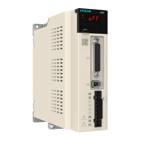
Veichi SD700 series User manual


Contents
I SD700 Series Servo Technical Manual
Contents
Contents.................................................................................................................................................I
Abstract.......................................................................................................................................11.
Series Introduction................................................................................................................11.1.
Name of Each Part of the Servo Drive.................................................................................11.2.
Basic Information of Servo Unit............................................................................................21.3.
Installation Dimensions ............................................................................................21.3.1.
Installation Way ........................................................................................................31.3.2.
Rated electrical parameters .....................................................................................31.3.3.
Basic specifications ..................................................................................................41.3.4.
System Diagram ...................................................................................................................81.4. System Configuration Example............................................................................................91.5.
Name the Drive...................................................................................................................101.6.
Maintenance and Inspection of Servo Unit........................................................................111.7.
Overhaul of Servo Motor ........................................................................................111.7.1.
Overhaul of Servo Drive.........................................................................................111.7.2.
Approximate Standards for Changing Internal Parts of Servo Units.....................111.7.3.
Panel Operation .......................................................................................................................122.
Basic Operation ..................................................................................................................122.1.
Keys’ Names and Functions of the Panel Operator ..............................................122.1.1.
Functions Switch ....................................................................................................132.1.2.
Status Display.........................................................................................................132.1.3.
Auxiliary Functions Operation of Fn group.........................................................................142.2.
Parameter Pn Group’s Operation.......................................................................................142.3.
Operations of Monitoring Display Un Group......................................................................152.4.
Wiring and Connections...........................................................................................................163.
Main Circuit Wiring..............................................................................................................163.1.
Terminals Explanation: ...........................................................................................163.1.1.
Wiring Diagram.......................................................................................................173.1.2.
B/C/D-volume three-phase wiring diagram............................................................183.1.3.
Definition of CN1 Terminal..................................................................................................193.1.
CN7 USB Communication Terminal Connection ...............................................................203.2.
CN6A and CN6B Communication Terminal Connection....................................................203.3.
CN5 Full Closed Loop Port.................................................................................................213.4.
Switch-Value Input Signal...................................................................................................233.5.
Input Signal Explanation.........................................................................................233.5.1.
Input Signal Configuration......................................................................................243.5.2.
Confirming the Input Status....................................................................................263.5.3.
Switching Output Signal .....................................................................................................273.6.
Output Signal Explanation......................................................................................273.6.1.
Output Signal Configuration...................................................................................273.6.2.
Confirming the Output Status.................................................................................283.6.3.
Connection with the Upper Device.....................................................................................293.7.
Analog Input Circuit 3 .............................................................................................293.7.1.

Contents
II SD700 Series Servo Technical Manual
Position Instruction Input Circuit ............................................................................293.7.2.
Connection example of open collector outtput ......................................................303.7.3.
Sequence Control Input Circuit ..............................................................................333.7.4.
Sequence Output Loop ..........................................................................................343.7.5.
Position Control Wiring Diagram........................................................................................373.8.
Speed Control Wiring Diagram ..........................................................................................383.9.
Torque Control Wiring Diagram........................................................................................393.10.
CN2 Encoder Connection.................................................................................................403.11.
Regenerative Resistor Connection ..................................................................................403.12.
Connection of Regenerative Resistors ................................................................403.12.1.
Selection of Regenerative Resistor..................................................................................403.13.
Noise and High Harmonic Countermeasures..................................................................413.14.
Trial operation...........................................................................................................................414.
Inspections and Notes before Trail Operation ...................................................................414.1.
Conditions of the Servo Motor:...............................................................................424.1.1.
Conditions of the Servo Drive ................................................................................424.1.2.
Installation...............................................................................................................424.1.3.
JOG trail operation .............................................................................................................424.2.
Operation..................................................................................................................................435.
Basic Functions ..................................................................................................................435.1.
Quick Guide............................................................................................................435.1.1.
Servo Enable and Over-range Setting...................................................................435.1.2.
Motor Rotation Direction.........................................................................................455.1.3.
Stop Mode...............................................................................................................455.1.4.
Electromagnetic Brake ...........................................................................................465.1.5.
Regenerative Resistor............................................................................................485.1.6.
Overload .................................................................................................................485.1.7.
Multi-turn Absolute Encoder...................................................................................495.1.8.
Torque Limit ............................................................................................................505.1.9.
Position Mode.....................................................................................................................525.2.
Quick Guide............................................................................................................535.2.1.
Basic Settings.........................................................................................................535.2.2.
Deviation Clearance ...............................................................................................565.2.3.
Command Pulse Prohibition...................................................................................575.2.4.
Positioning Approach..............................................................................................575.2.5.
Positioning Completion...........................................................................................585.2.6.
Command Pulse Input Magnification Switching ....................................................595.2.7.
Smooth Settings .....................................................................................................605.2.8.
Frequency Output...................................................................................................615.2.9.
Speed Mode........................................................................................................................635.3.
Quick Guide............................................................................................................645.3.1.
Basic Settings.........................................................................................................645.3.2.
Soft Start.................................................................................................................675.3.3.
Zero Fixed Functions..............................................................................................685.3.4.
Rotation Detection Signal.......................................................................................695.3.5.
Consistent Speed ...................................................................................................705.3.6.
Torque Mode.......................................................................................................................715.4.
Quick Guide............................................................................................................725.4.1.
Basic Settings.........................................................................................................725.4.2.

Contents
III SD700 Series Servo Technical Manual
Adjustment of Instruction Offset .............................................................................745.4.3.
Speed Limit in Torque Control................................................................................745.4.4.
Hybrid Control Mode Selection ..........................................................................................745.5.
Other Output Signals..........................................................................................................785.6.
Servo Ready Output Signal....................................................................................785.6.1.
Warning Output Signal ...........................................................................................785.6.2.
Timing..................................................................................................................................795.7.
Power Enable ON Timing.......................................................................................795.7.1.
Power-Off Enable OFF Timing...............................................................................805.7.2.
Adjustment................................................................................................................................806.
Adjustments ........................................................................................................................806.1.
Adjustments Steps..................................................................................................806.1.1.
Safety Precautions When Adjusting.......................................................................816.1.2.
Robust Control....................................................................................................................836.2.
Profile......................................................................................................................836.2.1.
Steps.......................................................................................................................846.2.2.
Supplement.............................................................................................................846.2.3.
Relevant Parameters..............................................................................................846.2.4.
Inertia Recognition..............................................................................................................866.3.
Profile:.....................................................................................................................866.3.1.
Steps.......................................................................................................................866.3.2.
Supplyment.............................................................................................................866.3.3.
Intelligent Setting ................................................................................................................876.4.
Profile......................................................................................................................876.4.1.
Steps.......................................................................................................................876.4.2.
Supplyment.............................................................................................................896.4.3.
Related Parameters................................................................................................906.4.4.
Bandwidth Setting...............................................................................................................916.5.
Profile......................................................................................................................916.5.1.
Steps.......................................................................................................................916.5.2.
Supplyment.............................................................................................................926.5.3.
Related Parameters................................................................................................936.5.4.
Manual Adjustment Function..............................................................................................946.6.
Servo Gain..............................................................................................................946.6.1.
Gain Switching........................................................................................................966.6.2.
Speed Feedforward................................................................................................996.6.3.
Torque Feedforward .............................................................................................1006.6.4.
P/PI Switching.......................................................................................................1006.6.5.
Accessibility ............................................................................................................................1057.
List of Auxiliary Functions.................................................................................................1057.1.
Displaying Alarm Logs (Fn000)........................................................................................1057.2.
Overview...............................................................................................................1057.2.1.
Operating Procedure ............................................................................................1067.2.2.
Clear Alarm Record (Fn001) ............................................................................................1067.3.
Summary...............................................................................................................1067.3.1.
Operating Procedure ............................................................................................1067.3.2.
Software Reset (Fn002) ...................................................................................................1067.4.
Summary...............................................................................................................1067.4.1.
Operating Procedure ............................................................................................1077.4.2.

Contents
IV SD700 Series Servo Technical Manual
Restoring Factory Parameters (Fn003) ...........................................................................1077.5.
Overview...............................................................................................................1077.5.1.
Operating Procedure ............................................................................................1077.5.2.
JOG Operation (Fn005)....................................................................................................1077.6.
Summary...............................................................................................................1077.6.1.
Operating Procedure ............................................................................................1087.6.2.
Program JOG Operation (Fn006).....................................................................................1087.7.
Summary...............................................................................................................1087.7.1.
Operating Procedure ............................................................................................1097.7.2.
Automatic Adjustment of Instruction Offset (Fn100) ........................................................1097.8.
Summary...............................................................................................................1097.8.1.
Operating Procedure ............................................................................................1097.8.2.
Speed Command Offset Manual Adjustment (Fn101).....................................................1107.9.
Summary...............................................................................................................1107.9.1.
Operating ..............................................................................................................1107.9.2.
Summary...............................................................................................................1107.9.3.
Operating Procedure ............................................................................................ 1117.9.4.
Current Offset Automatic Adjustment (Fn103)............................................................... 1117.10.
Summary............................................................................................................. 1117.10.1.
Operating Procedure .......................................................................................... 1117.10.2.
Current Offset Manual Adjustment (Fn104) ................................................................... 1117.11.
Overview ............................................................................................................. 1117.11.1.
Operating Procedure ..........................................................................................1127.11.2.
Initializing the Detection Value of Vibration Detection (Fn105).....................................1127.12.
Summary.............................................................................................................1127.12.1.
Operating Procedure..........................................................................................1137.12.2.
Bandwidth Settings (Fn303)...........................................................................................1137.13.
Summary.............................................................................................................1137.13.1.
7.14.2 Operating Procedure ...........................................................................................114
EasyFFT (Fn401)............................................................................................................1147.14.
Summary.............................................................................................................1147.14.1.
Operating Procedure ..........................................................................................1157.14.2.
Online Vibration Monitoring (Fn402)..............................................................................1157.15.
Overview.............................................................................................................1157.15.1.
Operating Procedure..........................................................................................1157.15.2.
Function Code Instructions ....................................................................................................1168.
Basic Control Related Pn0 Group Parameters................................................................1168.1.
Gain Related Pn1 Group ..................................................................................................1218.2.
Position Related Pn2 Group Parameters.........................................................................1288.3.
Speed Related Pn3 Group Parameters ...........................................................................1338.4.
Torque Related Pn4 Group Parameters...........................................................................1358.5.
Jogging Related Pn0 Group Parameters.........................................................................1378.6.
Switch Configuration Related Pn6 Group Parameters....................................................1378.7.
Expansion Related Pn7 Group Parameters.....................................................................1408.8.
Monitoring Parameters...........................................................................................................1419.
Fault Code and Countermeasures.........................................................................................14410.
Fault Code ......................................................................................................................14410.1.
Warning Code.................................................................................................................14910.2.
Communication.......................................................................................................................15011.

Contents
V SD700 Series Servo Technical Manual
Communication introduction...........................................................................................15011.1.
RS485 communication protocol description...................................................................15011.2.
Communication frame structure .....................................................................................15011.3.
Command code and communication data description...................................................15111.4.
Communication frame error check mode:......................................................................15311.5.
Error message response ................................................................................................15411.6.
Host Debugging Instruction....................................................................................................15512.
System Requirements....................................................................................................15512.1.
System Configuration.........................................................................................15512.1.1.
Connection Configuration...................................................................................15512.1.2.
Main Interface.................................................................................................................15612.2.
Features..........................................................................................................................15812.3.
Real-Time Monitoring .....................................................................................................16212.4.
Auxiliary Functions..........................................................................................................16312.5.
JOG.....................................................................................................................16312.5.1.
Inertia Identification ............................................................................................16412.5.2.
Mechanical Characteristics ................................................................................16612.5.3.
Analysis...............................................................................................................16812.5.4.
Bandwidth setting ...............................................................................................16812.5.5.
Offset Adjustment ...............................................................................................17012.5.6.
Soft Reset ...........................................................................................................17112.5.7.
Restoring the Factory Value...............................................................................17112.5.8.
Fault Information.................................................................................................17212.5.9.
Digital Oscilloscope ........................................................................................................17212.6.
Real-Time Acquisition.........................................................................................17512.6.1.
Trigger Acquisition ..............................................................................................17512.6.2.
Graphic Operations ............................................................................................17612.6.3.
Others .............................................................................................................................18112.7.
Window Display ..................................................................................................18112.7.1.
Help.....................................................................................................................18112.7.2.

Abstract
1
Abstract1.
Series Introduction1.1.
SD700 series servo drives are mainly used for the occasion of high speed, high frequency
and high positioning accuracy. The servo unit can maximize the performance of the machine in the
shortest time, which can improve the production efficiency.
Name of Each Part of the Servo Drive1.2.
Motor
encoder
line
port
Multi-function
control
port
Communication
RJ45
Host computer
micro USB
Operation
keyboard
Digital display tube
Rotate the
keyboard cover
Top full-closed
loop port
Heat sink
Servo nameplate
Power Indicator
Main circuit
power
Control power
Motor power
Safety
grounding
Braking unit
Main circuit power
protection cover

Abstract
2
Basic Information of Servo Unit1.3.
Installation Dimensions1.3.1.
W
H
DW1
H1
B
A
安装孔径
W2
Structure
Machine model
External size(mm)
Installation size(mm)
Installation
aperture
W
H
D
W1
W2
H1
H2
A
B
SIZE A
SD700-1R1A-**
45
168
170
\
20
160
\
7.5
5
2-M4
SD700-1R8A-**
SD700-3R3A-**
SIZE B
SD700-5R5A-**
71
168
180
58
58
160
\
6.5
5
3-M4
SD700-7R6A-**
SD700-9R5A-**
SD700-2R5D-**
SD700-3R8D-**
SIZE C
SD700-160A-**
92.5
188
182
82.5
75
180
\
5
5
3-M4
SD700-6R0D-**
SD700-8R4D-**
SD700-110D-**
SIZE D
SD700-170D-**
120
260
210
100
84.5
250
236
\
\
4-M5
SD700-240D-**
SD700-300D-**
Mounting aperture

Abstract
3
Installation Way1.3.2.
150mm
30mm
150mm
30mm
单台安装空间
150mm
30mm30mm 30mm
150mm
150mm 150mm
多台安装空间
Single installation Multiple installation
Rated electrical parameters1.3.3.
Drive specification
1R1A
1R8A
3R3A
5R5A
7R6A
9R5A
Continuous output
current Arms
1.1
1.8
3.3
5.5
7.6
9.5
Maximum output
current Arms
3.9
6.3
11.6
16.5
22.8
23.8
Case
A
B
Drive specification
2R5D
3R8D
6R0D
8R4D
110D
170D
240D
300D
Continuous output
current Arms
2.5
3.8
6
8.4
11
17
24
30
Maximum output
current Arms
7.5
11.4
18
25.2
27.5
42.5
60
70
Case
B
C
D

Abstract
4
Basic specifications1.3.4.
Project
Specifications
Control Mode
IGBT, PWM Control, Sine wave current drive
mode
Feedback
Rotary Motor Combination
Serial communication encoders: 17-bit, 20-bit,
24-bit (absolute encoder)
Pulse encoder: Provincial linear encoder: 2500
line
Rotary transformer type encoder
Environmental
conditions
Environment temperature
-5℃~55℃(55 ° C ~ 60 ° C, can reduce the
rated value to use)
Storage temperature
-20℃~85℃
Environmental humidity
Less 95%RH(No freezing, no condensation)
Storage humidity
Less 95%RH(No freezing, no condensation)
Vibration resistance
4.9m/s²
Impact resistance
19.6m/s²
Protection level
IP20
Cleanliness
Non-corrosive and flammable gas
No water, oil, pharmacy splash
Dust, salt, and metal powder are less in the
environment
Altitude
Below 1000m (1000m~2000m, can reduce
the rated value to use)
others
No static electricity interference, strong electric
field, strong magnetic noise, radiation, etc.
Applicable standard
EN 61800-5-1:2007
EN 61800-3:2004/A1:2012
Installation type
Base mounting Type: All models
Shelf mounting type: All models
Performa
nce
Speed control range
1:6000 (The lower limit of the speed control
range is the value under non-stop condition at
the rated torque load)
Speed fluctuation
rate
Load fluctuation
Below ± 0.01% of rated speed (load
fluctuation: 0%~100%)
Voltage fluctuation
Rated speed 0% (rated voltage ± 10%)
Temperature
fluctuation
Below ± 0.1% of rated speed (temperature
fluctuation: 25± 25° C)
Torque control accuracy
± 1%
Soft-start time setting
0~10s (acceleration and deceleration can be
set separately)

Abstract
5
Commun
ication
function
RS-485
1:N
communication
When RS-485 port, N max = 127 stations
Axis address
setting
Through parameter setting
USB communication
Connected
equipment
Computer
According to USB1.1 specification (12M)
Display function
Charge indicator
Panel operation function
Push button switch × 4
Input and
output
signals
Encoder divider pulse output
A-phase, B-phase, and C-phase: linear drive
transmission frequency pulse number, can
free to set
Sequence input
signal
Fixed input
Operating voltage range: DC 5V± 5%
Input points: 1 point
Encoder absolute data request input (SEN)
signal
Assignable input
signal
Operating voltage range: DC24V± 20%
Input points: 9 points
Input method: common collector input,
common emitter input
Input signal
Servo ON (/S-ON)
P operation/P-CON
Home reset deceleration switch signal (/DEC)
Forward drive prohibition (P-OT), reverse drive
prohibition (N-OT)
Alarm reset (/ALM-RST)
Forward external torque limit (/P-CL), reverse
external torque limit (/N-CL)
Speed rotation direction selection (/SPD-D)
signal
Control Mode Switch (/C-SEL)
Zero Fixed (/ZCLAMP)
Command Pulse Disable (/INHIBIT)
Magnetic pole detection input (/P-DET) signal
Gain switching (/G-SEL)
Command pulse input override switch (/PSEL)
SEN input (/SEN) signal
Assignable signals and change
positive/negative logic
Sequential output
Fixed output
Operating voltage range: DC5V~DC30V

Abstract
6
signal
Output points: 1 point
Output signal: servo alarm (ALM)
Assignable output
signal
Operating voltage range: DC5V~DC30V
Output points: 3 points
Input method: opt coupler output (isolated
type)
Output signal
Positioning completed (/COIN)
Rotary checkout (/TGON)
Servo ready (/S-RDY)
Torque Limit Detection (/CLT)
Speed Limit Checkout (/VLT)
Brakes (/BK)
Warning (/WARN)
Locate nearby (/NEAR)
Assignable signals and change
positive/negative logic
Dynamic brake
Operation in the main circuit power OFF,
servo alarm, servo OFF, and over-travel (OT)
Regenerative
Function built-in
Over-travel (OT) protection
Dynamic brake (DB) stop, deceleration stop or
free-running stop during P-OT, N-OT input
operation
Protective function
Over-current, over-voltage, under-voltage,
overload, regenerative failure, etc.
Accessibility function
Gain adjustment, alarm records, JOG
operation, origin search, etc.
Security
function
Input
STO: Base of the power module block signal
Control
method
Position
Control
Feed forward compensation
0%~100%
Location reach arrange
0~1073741824 instruction unit
Input
signal
Comm
and
pulse
Command
pulse form
Choose any of the followings
Symbol & pulse sequence, CW+CCW pulse
sequence, 90° phase difference two-phase
pulse
Input form
Linear drive, open collector
Maximum
input
frequency
Line driver
Symbol + pulse sequence, CW + CCW pulse
sequence: 4Mpps
90° phase difference two-phase pulse: 1Mpps
Open collector

Abstract
7
Symbol + pulse sequence, CW + CCW pulse
sequence: 200 Kpps
90° phase difference two-phase pulse:
200Kpps
Input
override
switch
1~100 times
Clear signal
Position deviation clearing
Speed
control
Soft-start time setting
0~10s (acceleration and deceleration can be
set separately)
input
signal
Command voltage
Maximum input voltage: ± 10V (Forward
rotation of motor when positive voltage is
commanded)
Rated speed at DC6V [factory setting]
Can change input gain setting
input resistance
About 14KΩ
Loop time parameter
30μs
Internal
ly set
speed
control
Rotation direction
selection
Use P operation signal
Speed selection
Using Forward/Reverse External Torque Limit
Signal Input
Stop or change to other control mode when
both sides are OFF
Torque
control
input
signal
Command voltage
Maximum input voltage: ± 10V (positive
rotation of motor when positive voltage is
commanded)
Rated speed at DC6V [factory setting]
Can change input gain setting
Input resistance
About 14KΩ
Loop time parameter
16μs

Abstract
8
System Diagram1.4.
Over-temperature/current
protection Dynamic
brake circuit
M
L1
L2
L3
Main
circuit
power
Rheost
at
Cha
rge
B1/⊕
2
B2 B3
Voltage
sampling
Delay Drive Temperature
sampling
Gate
drive
Current
sampling
Control
power
Rheostat
L1C
L2C
Control
power
ARM+FPGA
CN7 CN6
MicroUSB Dual RJ45 bus interface Full-closed loop and 2500 line interface
I/O
A/D
CN5
Input and
output signals
Command
voltage input
Encoder divider
pulse output
Command pulse
input
U
V
W
CN1
CN2
Servo motor
ENC
Fan
Bus encoder
interface
Panel operator

Abstract
9
System Configuration Example1.5.
AC200/400V
Circuit breaker
Fil
ter
Brake resistor
Brake
power
SD700 series servo drive
Battery unit (matches
with an absolute encoder)
VM7 series servo drive
Grating ruler
Contactor
Contactor

Abstract
10
Name the Drive1.6.
SD700-3R3A-PA*
A B C D E F G
Field ID
Field Explanation
A
SD:Servo product code
B
700:Product series
C
Current class:
1R1:1.1A 1R8:1.8A 3R3:3.3A 5R5:5.5A 7R6:7.6A 9R5:9.5A
2R5:2.5A 3R8:3.8A 6R0:6A 8R4:8.4A 110:11A 170:17A 240:
24A 300:30A
D
Input voltage class:
A:220VAC;D:400VAC
E
Type:
P: pulse type; S: standard type; C: CAN open bus type; N: Ether CAT bus type; M:
MECHATROLINK-II bus type; L: MECHATROLINK-III bus type
F
Supported encoder types:
A
Absolute type
B
Incremental
T
Rotary transformer type
G
Product management number, standard product default.
Difference functions between different types:
Code
model
Input
pulse
16-bit
analog
value
Full
closed
loop
RS485
CAN
open
Ether
CAT
MECHATRO
LINK Ⅱ
MECHATRO
LINK Ⅲ
P
Pulse type
√
×
×
√
×
×
×
×
S
Standard type
√
√
√
√
×
×
×
×
C
CAN type
×
×
×
×
√
×
×
×
N
Ether CAT type
×
×
×
×
×
√
×
×
M
MECHATROLINK
Ⅱtype
×
×
×
×
×
×
√
×
L
MECHATROLINK
Ⅲtype
×
×
×
×
×
×
×
√
*1.M-II type refers to the servo unit interface specification for MECHATROLINK-II
communication command type
*2.M-III type refers to the servo unit interface specification for MECHATROLINK-III
communication command type

Abstract
11
Maintenance and Inspection of Servo Unit1.7.
The servo system is made up of many parts. The equipment performs its functions only when
all the parts work properly. In mechanical parts and electronic parts, some parts need to be
maintained depending on the conditions of use. It must be regularly checked or replaced according
to the service-time to ensure that the servo motor and servo drive can operate normally for a long
time.
Overhaul of Servo Motor1.7.1.
Since the AC servo motor does not have the electric brush so that only a simple daily
maintenance is required. The maintenance period in the table is a rough standard. Please judge
and determine the most appropriate time for repair according to the conditions of use and use
environment.
Inspect items
Inspect
time
The essentials of inspection
and maintenance
Notes
Vibration and
sound
confirmation
every day
Tactile and auditory judgments
No increase
compared to usual
Appearance
overhaul
According to
the insult
Erasing with a cloth or cleaning
with an air gun
-
Insulation
resistance
measurement
At least once a
year
Disconnect the servo unit and
measure the insulation
resistance with a 500V megger.
Resistance value exceeding
10MΩ is normal
When it is 10MΩ or
less, please contact
our maintenance
department.
Replacement of oil
seals
At least once
every 5000
hours
Please contact our agents or
technical support.
Only servo motor with
oil seal.
Comprehensive
maintenance
At least once
every 20,000
hours or 5
years
-
Overhaul of Servo Drive1.7.2.
Although the servo drive unit does not require daily inspections, it should be overhauled more
than once a year.
Maintenance
project
Inspect time
The essentials of inspection and
maintenance
Notes
Appearance
maintenance
more than
once a year
No garbage, dust, oil traces, etc.
Erasing with a
cloth or cleaning
with an air gun
Loose
screws
Wiring board, connector mounting screws
and so on must not loosen
Please tighten
Approximate Standards for Changing Internal Parts of Servo Units1.7.3.
Electrical and electronic parts are subject to mechanical wear and aging. To ensure safety,

Panel Operation
12
please do regular inspections. In addition, please refer to the following table for the standard
number of years of replacement, and contact our agency or sales office. After the inspection, we
will judge whether we need to replace the parts. The servo unit serviced by our company has its
user parameters adjusted back to the factory settings. Be sure to reset the user parameters before
use by yourself.
Parts’ name
Standard replacement
period
Conditions of use
Cooling fan
4~5 years
Ambient temperature: annual
average 30° C
Load rate: 80% or less
Operating rate: 20 hours or less
Smoothing capacitor
7~8 years
Relay
According to actual use
conditions
Aluminum electrolytic capacitors
on printed circuit boards
5 years
Panel Operation2.
Basic Operation2.1.
Keys’ Names and Functions of the Panel Operator2.1.1.
The panel operator consists of panel monitor and keys. The panel operator could display
condition, operate the accessory functions, set parameters and monitor the motions of the drive
unit. The panel operator keys’ names and functions are shown as below:
MODE
SET
DATA

Panel Operation
13
Keys’ name
Functions
MODE/SET key
Shift the function modes
Confirm parameter settings
Operate the accessory functions
UP key
Select parameters up or increase the value, switch between high, medium,
and low segment values in multiple segment display parameters
▼ DOWN key
Select parameters down or decrease the value, switch between high,
medium, and low segment values in multiple segment display parameters
DATA/SHIFT
key
Press and hold the DATA/SHIFT button for about 1 second to enter or exit
Short press to move to the left one (when flashing)
Caution
!Pressing the Up and Down keys at the same time could reset the drive alarm, but remember to exclude
causes of the alarm before reset the drive alarm.
Functions Switch2.1.2.
Press the MODE/SET key, the function will be switched like this shown as below:
Parameter
s setting
Aux
functions Monitoring
Status
display
MODE/SET MODE/SET MODE/SET
MODE/SET
Status Display2.1.3.
The method of judging the status display is as follows:

Panel Operation
14
Displ
ay Meaning Meaning
Displ
ay
Means that the drive is OFF
Means that the drive is ON
Means that the input signal(P-
OT)is an open circuit
Means that the input signal(N-OT) is
an open circuit
Flashing displays fault code, more
details on the fault code
No-motor testing function displays the
running status alternately, more
details in this function
Disp
lay Meaning Meaning
Disp
lay
It lights on when the control power
is ON and lights off when OFF
Speed control: speed outputs(/V-
CMP) are absolutely same
Position control: it lights on when
the positioning is OK(/COIN)
Torque control: it lights on all
the time
It lights on when the drive is OFF
and lights off when ON
It lights on when the main circuit is
ON and lights off when OFF
It lights on when the rotation detection
outputs(/TGON)
Speed control: it lights on when the
speed command inputs
Position control: it lights on when the
position command inputs
Torque control: it lights on when the
torque command inputs
Position control: it lights on when the
pulse clear signal outputs
Auxiliary Functions Operation of Fn group2.2.
Auxiliary functions are about performing the settings and adjustment of the drive unit. The
panel operator displays the numbers which begin with Fn.
Let’s take the JOG function (Fn005) as an example to explain the operating method of the
auxiliary functions:
JOG
Aux
functions
JOG
prepare
Any
interface
MODE/SET UP Long press
DATA/SHIFT JOG
enable ON
MODE/SET UP:Forward
DOWN: Reversal
JOG
motion
JOG
prepare
JOG
MODE/SET
Long press
DATA/SHIFT
Long press
DATA/SHIFT
Parameter Pn Group’s Operation2.3.
Let me introduce the parameters Pn’s setting method:Take the setting method of the speed
loop gain rise from 40.0 to 100.0 as an example:
1. When the setting range is within 5-digit numbers. Because the panel operator could
only display 5-digit number, so the setting display with 6-digit number is shown as
Other manuals for SD700 series
3
Table of contents
Other Veichi Servo Drive manuals
Popular Servo Drive manuals by other brands

YASKAWA
YASKAWA E-S Series product manual

Stober
Stober EZ Series operating manual

Danfoss
Danfoss VLT AutomationDrive FC 360 quick guide

Elmo
Elmo SimplIQ Series Command reference manual

BONFIGLIOLI
BONFIGLIOLI TQ Installation use and service manual

Copley Controls
Copley Controls Xenus Plus Series user guide