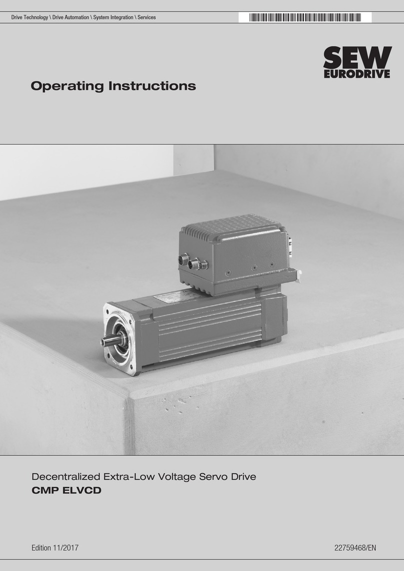
SEW-Eurodrive CMDV55M User manual

Drive Technology \ Drive Automation \ System Integration \ Services
Operating Instructions
Synchronous Compact Servomotors
CMDV55 – CMDV162

SEW-EURODRIVE—Driving the world

Operating Instructions – Synchronous Compact Servomotors CMDV55 – CMDV162 3
Contents
Contents
1 General Information............................................................................................ 5
1.1 Use of this documentation .......................................................................... 5
1.2 Structure of the safety notes....................................................................... 5
1.3 Rights to claim under limited warranty........................................................ 6
1.4 Exclusion of liability..................................................................................... 6
1.5 Copyright..................................................................................................... 6
1.6 Product names and trademarks.................................................................. 6
2 Safety Notes ........................................................................................................ 7
2.1 Preliminary information ............................................................................... 7
2.2 General information .................................................................................... 7
2.3 Target group ............................................................................................... 8
2.4 Designated use........................................................................................... 8
2.5 Transport/storage........................................................................................ 9
2.6 Installation .................................................................................................. 9
2.7 Electrical connection................................................................................... 9
2.8 Startup/operation ...................................................................................... 10
3 Motor Structure ................................................................................................. 11
3.1 Block diagrams of the synchronous servomotors ..................................... 11
3.2 Nameplate and type designation .............................................................. 13
3.3 Accessory equipment................................................................................ 15
4 Mechanical Installation..................................................................................... 16
4.1 Before you start......................................................................................... 16
4.2 Required tools/resources.......................................................................... 16
4.3 Long-term storage of servomotors............................................................ 16
4.4 Motor installation notes............................................................................. 17
4.5 Installation tolerances ............................................................................... 18
5 Electrical Installation ........................................................................................ 19
5.1 Additional regulations................................................................................ 19
5.2 Compulsory use of the wiring diagrams.................................................... 19
5.3 Wiring notes.............................................................................................. 19
5.4 Connecting power and signal cables via connector system .................... 20
5.5 Connecting the motor and the encoder system via
plug connector SM. / SB. .......................................................................... 21
5.6 Accessory equipment................................................................................ 28
6 Startup................................................................................................................ 30
6.1 Before startup ........................................................................................... 31
6.2 During startup ........................................................................................... 31
7 Inspection/Maintenance ................................................................................... 32
7.1 General information ................................................................................. 33

4Operating Instructions – Synchronous Compact Servomotors CMDV55 – CMDV162
Contents
8 Technical Data of the CMDV Servomotors ..................................................... 34
8.1 Mechanical/electrical characteristics......................................................... 34
8.2 Thermal classification and degrees of protection for the motor ................ 35
8.3 CMDV motor data ..................................................................................... 36
8.4 Inverter assignment MOVIDRIVE®MDX60B/61B .................................... 38
8.5 MOVIAXIS®inverter assignment.............................................................. 43
8.6 Torque-current characteristics .................................................................. 48
8.7 Dynamic limit characteristic curves........................................................... 51
8.8 Derating for increased ambient temperature ............................................ 74
8.9 Derating for high installation altitudes....................................................... 74
8.10 Accessories – technical data .................................................................... 75
8.11 Dimension drawings CMDV compact servomotors................................... 79
8.12 Overhung and axial loads on the shaft ................................................... 115
9 Prefabricated Cables ...................................................................................... 127
9.1 Project planning for cable cross section ................................................. 127
9.2 Cable assignment to CMDV, 400 V system voltage ............................... 128
9.3 Cable assignment to CMDV /BP, 400 V system voltage ........................ 130
9.4 Encoder cable assignment...................................................................... 132
9.5 Power cables .......................................................................................... 133
9.6 Feedback cables..................................................................................... 138
9.7 Encoder cables ....................................................................................... 144
9.8 Cable specification.................................................................................. 144
10 Malfunctions.................................................................................................... 149
10.1 Customer service.................................................................................... 149
10.2 Servomotor malfunctions ........................................................................ 150
10.3 Malfunctions of the servo inverter........................................................... 150
10.4 Brake malfunctions ................................................................................. 151
10.5 Disposal .................................................................................................. 151
11 Address List .................................................................................................... 152
Index................................................................................................................. 163

Operating Instructions – Synchronous Compact Servomotors CMDV55 – CMDV162 5
1
Use of this documentation
General Information
Synchronous CompactServomotors CMDV55 – CMDV162
1 General Information
1.1 Use of this documentation
The documentation is an integral part of the product and contains important information
on operation and service. The documentation is written for all employeeswho assemble,
install, start up, and service this product.
The documentation must be accessible and legible. Make sure that persons responsible
for the system and its operation, as well as persons who work independently on the unit,
have read through the documentation carefully and understood it. If you are unclear
about any of the information in this documentation, or if you require further information,
contact SEW-EURODRIVE.
1.2 Structure of the safety notes
1.2.1 Meaning of signal words
The following table shows the grading and meaning of the signal words for safety notes,
warnings regarding potential risks of damage to property, and other notes.
1.2.2 Structure of the section-related safety notes
Section-related safety notes do not apply to a specific action, but to several actions
pertaining to one subject. The used symbols indicate either a general or a specific
hazard.
This is the formal structure of a section-related safety note:
1.2.3 Structure of the embedded safety notes
Embedded safety notes aredirectly integrated in the instructions just before the descrip-
tion of the dangerous action.
This is the formal structure of an embedded safety note:
•SIGNAL WORD Nature and source of hazard.
Possible consequence(s) if disregarded.
– Measure(s) to prevent the danger.
Signal word Meaning Consequences if disregarded
DANGER Imminent danger Severe or fatal injuries
WARNING Possible dangerous situation Severe or fatal injuries
CAUTION Possible dangerous situation Minor injuries
NOTICE Possible damage to property Damage to the drive system or its
environment
INFORMATION Useful information or tip: Simpli-
fies the handling of the drive
system.
SIGNAL WORD
Type and source of danger.
Possible consequence(s) if disregarded.
• Measure(s) to prevent the danger.

6Operating Instructions – Synchronous Compact Servomotors CMDV55 – CMDV162
1Rights to claim under limited warranty
General Information
1.3 Rights to claim under limited warranty
A requirement of fault-free operation and fulfillment of any rights to claim under limited
warranty is that you adhere to the information in the documentation. Read the documen-
tation before you start working with the unit!
1.4 Exclusion of liability
You must comply with the information contained in this documentation to ensure safe
operation and to achieve the specified product characteristics and performance
features. SEW-EURODRIVE assumes no liability for injury to persons or damage to
equipment or property resulting from non-observance of these operating instructions. In
such cases, any liability for defects is excluded.
1.5 Copyright
© 2012 – SEW-EURODRIVE. All rights reserved.
Unauthorized duplication, modification, distribution or any other use of the whole or any
part of this documentation is strictly prohibited.
1.6 Product names and trademarks
All product names in this documentation are trademarks or registered trademarks of
their respective titleholders.

Operating Instructions – Synchronous Compact Servomotors CMDV55 – CMDV162 7
2
Preliminary information
Safety Notes
2 Safety Notes
The following basic safety notes must be read carefully to prevent injury to persons and
damage to property. The operator must ensure that the basic safety notes are read and
adhered to. Make sure that persons responsible for the system and its operation, as well
aspersonswho workindependentlyon theunit,have readthroughthe operatinginstruc-
tions carefully and understood them. If you are unclear about any of the information in
this documentation or if you require further information, please contact SEW-
EURODRIVE.
2.1 Preliminary information
The following safety notes are primarily concerned with the use of the following compo-
nents: CMDV motors. If using gearmotors, please also refer to the safety notes in the
corresponding operating instructions for:
• Motors
Also observe the supplementary safety notes in the individual sections of this documen-
tation.
2.2 General information
Removing the required protection cover or the housing without authorization, improper
use as well as incorrect installation or operation may result in severe injuries to persons
or damage to property.
This documentation provides additional information.
WARNING
During operation, the motors and gearmotors can have live, bare (in the event of open
connectors/terminal boxes) and movable or rotating parts as well as hot surfaces,
depending on their enclosure.
Severe or fatal injuries.
• All work related to transportation, storage, installation, assembly, connection,
startup, maintenance and repair may only be carried out by qualified personnel, in
strict observance of:
– The relevant detailed operating instructions
– The warning and safety signs on the motor/gearmotor
– All other project planning documents, operating instructions and wiring
diagrams related to the drive
– The specific regulations and requirements for the system
– The national/regional regulations governing safety and the prevention of
accidents
• Never install damaged products
• Immediately report any damage to the shipping company

8Operating Instructions – Synchronous Compact Servomotors CMDV55 – CMDV162
2Target group
Safety Notes
2.3 Target group
Any mechanical work may only be performed by adequately qualified personnel. Quali-
fied staff in the context of this documentation are persons familiar with the design,
mechanical installation, troubleshooting and servicing of the product who possess the
following qualifications:
• Training in mechanical engineering, e.g. as a mechanic or mechatronics technician
(final examinations must have been passed).
• They are familiar with these operating instructions.
Any electronic work may only be performed by adequately qualified electricians. Quali-
fied electricians in the context of this documentation are persons familiar with electrical
installation, startup, troubleshooting and servicing of the product who possess the
following qualifications:
• Training in electrical engineering, e.g. as an electrician, electronics or mechatronics
technician (final examinations must have been passed).
• They are familiar with these operating instructions.
All work in further areas of transportation, storage, operation and waste disposal must
only be carried out by persons who are trained appropriately.
All qualified personnel must wear appropriate protective clothing.
2.4 Designated use
The CMDV motors are intended for industrial systems.
When installed in machines, startup (i.e. start of designated operation) is prohibited until
it is determined that the machine complies with the local laws and directives. In the
individual area of application, you must especially observe the Machinery Directive
2006/42/EC as well as the EMC Directive 2004/108/EC. The EMC test specifications
EN 61000-4-2, EN 61000-4-3, EN 61000-4-4, EN 61000-4-6 and EN 61000-6-2 form
the basis for this.
Use in potentially explosive atmospheres is prohibited unless specifically designated
otherwise.
Air-cooled motors/gearmotors are dimensioned for ambient temperatures of -20 °C to
+40 °C and installation altitudes ≤1000 m above sea level. Any differing specifications
on the nameplate must be observed. The ambient conditions must comply with all the
specifications on the nameplate.

Operating Instructions – Synchronous Compact Servomotors CMDV55 – CMDV162 9
2
Transport/storage
Safety Notes
2.5 Transport/storage
Inspect the shipment for any damage that may have occurred in transit as soon as you
receive the delivery. Inform the shipping company immediately. It may be necessary to
preclude startup.
Tighten the eyebolts securely. They are designed to only carry the weight of the
motor/gearmotor; do not attach any additional loads.
The built-in lifting eyebolts comply with DIN 580. Always observe the loads and regula-
tions listed in this standard. If the gearmotor is equipped with two eyebolts, then both
should be used for transportation. In this case, the tension force vector of the slings must
not exceed a 45° angle according to DIN 580.
Use suitable, sufficiently rated handling equipment if required. Reattach these in the
case of further transportation.
Store the motor/gearmotor in a dry, dust-free environment if it is not to be installed
straight away. You must not store the motor/gearmotor outdoors or on the fan guard.
The motor/gearmotor can be stored for up to 9 months without requiring any special
measures before startup.
2.6 Installation
Make sure that the supports are even, the foot and flange mounting is correct and if
there is direct coupling, align with precision. Resonances between the rotational
frequency and the double network frequency caused by the structure are to be avoided.
Release the brake (if installed), turn rotor manually, check for unusual grinding noise.
Check the direction of rotation in decoupled status.
Only install or remove belt pulleys and couplings using suitable devices (heat up) and
cover with a touch guard. Avoid improper belt tension.
Make the pipe connections that may eventually be required. Mounting positions with
shaft ends pointing upwards should be equipped with a cover to prevent foreign objects
from falling into the fan. Ensure that ventilation openings are not obstructed and that
used air, including air from adjacent units, cannot be drawn in again straight away.
Observe the notes in the "Mechanical Installation" section.
2.7 Electrical connection
2.7.1 Brakemotor
All work may only be carried out by qualified personnel. During work, the low-voltage
machine must be at standstill, de-energized, and safeguarded against accidental
restart. This also applies to auxiliary circuits (e.g. anti-condensation heating or forced
cooling fan).
Check whether the motor is de-energized!
Exceeding the tolerances in EN 60034-1 (VDE 0530, part 1) – voltage + 5%, frequency
+ 2%, curve shape, symmetry – increases the heating and influences electromagnetic
compatibility. Also comply with EN 50110 (where necessary, observe other applicable
national regulations, such as DIN VDE 0105 for Germany).
Observe the wiring information and any differing data on the nameplate as well as the
wiring diagram in the terminal box.
The connection must be a permanently secure electrical connection (no protruding wire
ends); use the cable end equipment intended for this purpose. Establish a secure
10 Operating Instructions – Synchronous Compact Servomotors CMDV55 – CMDV162
2Startup/operation
Safety Notes
protective earth connection. When the motor is connected, the distances to non-insu-
lated and live parts must not be shorter than the minimum values according to IEC
60664 and national regulations. With low voltage, the distances should be no shorter
than the following values, in compliance with IEC 60664:
The terminal box must be free from foreign objects, dirt and humidity. Unused cable
entry openings and the box itself must be closed so that they are dust- and water-proof.
Secure the key for test mode without output elements. When operating low-voltage
machines with brakes, check that the brake is functioning correctly before startup.
Observe the notes in the "Electrical Installation" chapter.
2.8 Startup/operation
Whenever changes to normal operation occur, such as increased temperatures, noise,
vibrations, etc., try to determine the cause. Consult the manufacturer if required. Never
deactivate protection devices, even in test mode. Switch off the motor in case of doubt.
Regularly clean air ducts in dusty or dirty environments.
2.8.1 Surface temperature during operation
Servomotors/brakemotors get very hot during operation.
Touching the servomotor/brakemotor can result in burns if it has not cooled down. The
servomotor can have a surface temperature of more than 100 °C during operation.
Never touch the servomotor/brakemotor during operation or during the cool-down phase
once it has been switched off.
Rated voltage UNDistance
≤500 V 3 mm
≤690 V 5.5 mm

Operating Instructions – Synchronous Compact Servomotors CMDV55 – CMDV162 11
3
Block diagrams of the synchronous servomotors
Motor Structure
3 Motor Structure
3.1 Block diagrams of the synchronous servomotors
3.1.1 CMDV55 – CMDV162
The following figure shows the structure of a servomotor.
The following figure shows the structure of a servo brakemotor.
INFORMATION
The following illustrations are intended to explain the general structure. Differences
are possible depending on the motor size and design.
[1] Rotor (key optional)
[11] Grooved ball bearing
[16] Stator
[42] Endshield
[44] Grooved ball bearing
[105] Shim
[106] Oil seal
[304] Cover
[305] Resolver
[313] SM power plug connector / SB.
[318] Signal plug connector
[1]
[11]
[105]
[106] [313]
[44]
[16] [42]
[305]
[304]
[318]

12 Operating Instructions – Synchronous Compact Servomotors CMDV55 – CMDV162
3Block diagrams of the synchronous servomotors
Motor Structure
[1] Rotor (key optional)
[11] Grooved ball bearing
[16] Stator
[70] Driver pinion
[106] Oil seal
[299] Brake housing
[313] SM power plug connector / SB.
[318] Signal plug connector
[550] BP holding brake
[299]
[550]
[70]
[16]
[1] [11]
[106]
[313]
[318]

Operating Instructions – Synchronous Compact Servomotors CMDV55 – CMDV162 13
3
Nameplate and type designation
Motor Structure
3.2 Nameplate and type designation
3.2.1 CMDV motor nameplate
The following figure shows a nameplate:
3.2.2 Type designation of a servomotor
The following diagram shows a type designation:
12
4.2 2.2
13.8
CMDV 93M /BP /KY /AK0H /SB1
Plug connector as standard
• SM1 / SMB (motor)
• SB1 / SBB (brakemotor)
Motor option
• RH1M resolver
•HIPERFACE
®encoders AK0H,
EK0H for CMDV55 – CMDV162
•HIPERFACE
®encoders AK1H,
EK1H für CMDV93 – CMDV162
Standard equipment: KTY temperature
sensor
Motor option: holding brake
• CMDV55: BP01
• CMDV70: BP04
• CMDV93: BP09
• CMDV138: BP3
• CMDV162: BP5
Size
• 55S, 55M, 55L
• 70S, 70M, 70L
• 93K, 93S, 93M, 93L
• 138K, 138S, 138M, 138L
• 162K, 162S, 162M, 162L
CMDV compact servomotor series
• V: Solid shaft

14 Operating Instructions – Synchronous Compact Servomotors CMDV55 – CMDV162
3Nameplate and type designation
Motor Structure
3.2.3 Serial number
01. 1221234301. 0001. 12
End digits of the year of manufacture (2 digits)
Quantity (4 digits)
Order item (2 digits)
Order number (8 digits)
Sales organization

Operating Instructions – Synchronous Compact Servomotors CMDV55 – CMDV162 15
3
Accessory equipment
Motor Structure
3.3 Accessory equipment
3.3.1 Mechanical additions
3.3.2 Encoder
3.3.3 Connection variants
3.3.4 Other additional features
Designation Description
/BP Holding brake for CMDV55 – CMDV162
Designation Description
/RH1M Resolver (standard)
/EK0H Single-turn HIPERFACE®encoder, cone shaft, for CMDV55 –
CMDV162
/AK0H Multi-turn HIPERFACE®encoder, cone shaft, for CMDV55 –
CMDV162
/EK1H Single-turn HIPERFACE®encoder, cone shaft, for CMDV93 –
CMDV162
/AK1H Multi-turn HIPERFACE®encoder, cone shaft, for CMDV93 –
CMDV162
Designation Description
/SM1 Motor plug connector M23, only connectors for motor side,
motor and encoder cable pluggable.
For CMDV55 – CMDV162 (standard)
/SMB Motor plug connector M40, only connectors for motor side,
motor and encoder cable pluggable. For CMDV138 –
CMDV162
/SB1 Brakemotor plug connector M23, only connectors for motor
side, motor and encoder cable pluggable.
For CMDV55 – CMDV162 (standard)
/SBB Brakemotor plug connector M40, only connectors for motor
side, motor and encoder cable pluggable. For CMDV138 –
CMDV162
Designation Option/description
Shaft available with keyway
IP66 degree of protection

16 Operating Instructions – Synchronous Compact Servomotors CMDV55 – CMDV162
4Before you start
Mechanical Installation
4 Mechanical Installation
4.1 Before you start
Install the drive only if the following conditions are met:
• The drive must be undamaged (no damage caused by shipping or storage).
• All securing devices must be removed.
• The information on the nameplate must indicate that the drive is suitable for opera-
tion on a servo inverter.
• The ambient temperature is between -20 °C and +40 °C.
• The installation altitude must be no higher than 1000 m above sea level, otherwise
the drive must be designed to meet the special environmental conditions.
• The surrounding area is free from oils, acids, gases, vapors, radiation, etc.
4.2 Required tools/resources
• Standard tools
• For plug connectors assembled by the customer:
• Crimping pliers up to a cable cross section of 10 mm2(see "Prefabricating
Cables" manual)
• Crimping pliers from a cable cross section of 16 mm2(see "Prefabricating
Cables" manual)
• Removal tool for insulator for changing the connector.
4.3 Long-term storage of servomotors
Observe the following notes when you take a stored motor into operation:
• The service life of the ball bearing grease is reduced after storage periods exceeding
one year.
• SEW-EURODRIVE recommends to have the motor inspected by SEW Service after
4 years in storage to check the ball bearing grease for signs of ageing.
• Check whether the servomotor has absorbed moisture as a result of being stored for
a long time. Measure the insulation resistance with a measurement voltage of
DC 500 V.
The insulation resistance varies greatly depending on the temperature. You
can measure the insulation resistance between the connection pins and the
motor housing using an insulation measuring device. The motor must be dried
by the Service of SEW-EURODRIVE if theinsulation resistance is not adequate.
The following figure shows the insulation resistance depending on the temperature.

Operating Instructions – Synchronous Compact Servomotors CMDV55 – CMDV162 17
4
Motor installation notes
Mechanical Installation
Insulation resistance depending on the temperature
4.3.1 Insulation resistance too low
4.4 Motor installation notes
• Motor shaft ends must be thoroughly cleaned of anti-corrosion agents, contamination
or similar. Use a commercially available solvent. Solvent may not get in contact with
bearing or sealing rings because it may damage material.
• Make sure the customer's counter-bearing is unobstructed and can move freely.
• Make sure that the CMDV motors is not subject to overhung loads and bending
moments.
• Do not jolt or hammer the shaft or spindle end.
[1] Resistance/temperature point (RT point)
100
10
1
0,1 020 40 60 80
[˚C]
[MΩ]
[1]
INFORMATION
Insulation resistance too low:
• Servomotor has absorbed moisture.
Measure: Send the servomotor to the SEW-EURODRIVE Service with a description
of the fault.
CAUTION
For shafts with key: Sharp edges due to open keyway.
Minor injuries.
• Insert the key into the keyway.
• Push the protective hose over the shaft.
NOTICE
Improper assembly may damage the CMDV motors.
Possible damage to property
• Observe the following notes.

18 Operating Instructions – Synchronous Compact Servomotors CMDV55 – CMDV162
4Installation tolerances
Mechanical Installation
• Protect the components from mechanical damage.
• Only install the gearmotorin the specified mountingposition on a level, vibration-free
and torsionally rigid support structure.
• Align the motor and the driven machine carefully in order to prevent the output shaft
from being exposed to unacceptable strain. Observe the permitted overhung and
axial forces.
• Provide for sufficient clearance around the motor to allow for adequate cooling.
• Heat is dissipated (cooling) also via the primary flanges on the output shaft end. To
achieve the rated power, themounting surface must be dimensioned so that the heat
can be dissipated.
• Make sure that the warm exhaust air of other devices is not sucked in.
• For shafts with keyway: Balance components for subsequent mounting on the shaft
with a half key (motor shafts are balanced with a half key).
4.4.1 Installation in damp locations or in the open
• Try to arrange themotor and encoder connection so that the connectorcables do not
point upwards.
• Clean the sealing surfaces of the connector (motor or encoder connection) before re-
assembly.
• Replace any brittle seals.
• If necessary, restore the anticorrosive paint coat.
• Check that the degree of protection is maintained.
• If necessary, attach covers (protection canopy).
4.5 Installation tolerances
Shaft end Flanges
Diameter tolerance in accordance with DIN 748
•ISOk6
• Center bore to DIN 332
Centering shoulder tolerance in accordance with
EN 50347
•ISOj6

Operating Instructions – Synchronous Compact Servomotors CMDV55 – CMDV162 19
5
Additional regulations
Electrical Installation
5 Electrical Installation
• It is essential to comply with the safety notes in chapter 2 during installation!
• Switch contacts in utilization category AC-3 to EN 60947-4-1 must be used for
switching the motor and the brake.
• Use switch contacts in utilization category DC-3 according to EN 60947-4-1 for
switching the brake with DC 24 V.
• When motors are powered by inverters, you must adhere to the wiring instructions
issued by the inverter manufacturer.
• Observe the operating instructions of the inverter.
5.1 Additional regulations
Thegenerallyapplicable installation regulations for low-voltage electric equipment (such
as DIN IEC 60364, DIN EN 50110) must be complied with when setting up electrical
machinery.
5.2 Compulsory use of the wiring diagrams
Connect the motor only as shown in the wiring diagram(s) included with the motor. Do
not connect or start up the motor if the wiring diagram is missing. The relevant
wiring diagrams are available from SEW-EURODRIVE free of charge.
5.3 Wiring notes
5.3.1 Protecting the brake control system against interference
To protect the brake control system against interference, do not route unshielded brake
cables together with switched-mode power cables.
Switched-mode power cables include in particular:
• Output cables from servo inverters, converters, soft start units and brake units
• Supply cables for braking resistors and similar options
WARNING
Danger of electric shock.
Severe or fatal injuries!
• Observe the following notes.

20 Operating Instructions – Synchronous Compact Servomotors CMDV55 – CMDV162
5Connecting power and signal cables via connector system
Electrical Installation
5.3.2 Thermal motor protection
5.4 Connecting power and signal cables via connector system
The cable entry of the power and signal cables is installed using plug connectors.
One the mating connector has been plugged in, optional right-angle connectors can be
adjusted as required without using additional tools. A torque of > 8 Nm is required to
adjust the connector.
5.4.1 Connector positions
A "radial" position has been defined for the straight plug connectors (radial output). The
radial plug connectors [1] correspond to the standard.
The position "adjustable" was defined for right-angle, adjustable connectors [2].
NOTICE
Electromagnetic interference of the drives.
Possible damage to property.
• Install the connecting lead of the KTY separately from other power cables maintain-
ing a distance of at least 200 mm. The cables can only be routed together if either
the KTY cable or the power cable is shielded.
NOTICE
Damage of the right-angle connector in case of rotation without mating connector.
Possible damage to property.
• Do not use pliers to adjust the right-angle connector before connecting it. This
might damage the thread and the sealing surface.
[1] "Radial" connector position
(standard) [2] "Adjustable" connector position
(optional)
2
1
This manual suits for next models
17
Table of contents
Other SEW-Eurodrive Servo Drive manuals

SEW-Eurodrive
SEW-Eurodrive MOVITRAC LTX Operating instructions

SEW-Eurodrive
SEW-Eurodrive CMP40 User manual

SEW-Eurodrive
SEW-Eurodrive CMP Series Operating instructions

SEW-Eurodrive
SEW-Eurodrive CM3C Series User manual

SEW-Eurodrive
SEW-Eurodrive DFS Series User manual

SEW-Eurodrive
SEW-Eurodrive DR Series User manual

SEW-Eurodrive
SEW-Eurodrive CMP ELVCD User manual

SEW-Eurodrive
SEW-Eurodrive CM3C Series User manual

SEW-Eurodrive
SEW-Eurodrive CMP Series Operating instructions

SEW-Eurodrive
SEW-Eurodrive Movidrive MDX60B User manual