Leadtek LR9548S User manual

LR9548S
GPS Module
LR9548S
GPS Module

Copyright
©2006 Leadtek Research Inc. All rights reserved. No part of this publication may be reproduced, stored in a retrieval
system, or transmitted in any form or by any means, electronic, mechanical, photocopying, recording or otherwise,
without the prior written consent of Leadtek Research Inc.
Trademarks
Leadtek and the Leadtek logo are registered trademarks of Leadtek Research Inc.
All other trademarks are the property of their respective owners.
Changes
The material in this document is for information only and is subject to change without notice. While reasonable efforts
have been made in the preparation of this document to assure its accuracy, Leadtek Research assumes no liability
resulting from errors or omissions in this document, or from the use of the information contained herein.
Leadtek reserves the right to make changes in the product design without reservation and without notification to its
users.
THE DOCUMENT IS PROVIDED BY LEADTEK "AS IS", AND ANY EXPRESS OR IMPLIED WARRANTIES,
INCLUDING, BUT NOT LIMITED TO, THE IMPLIED WARRANTIES OF MERCHANTABILITY AND
FITNESS FOR A PARTICULAR PURPOSE ARE DISCLAIMED. IN NO EVENT SHALL LEADTEK BE LIABLE
FOR ANY DIRECT, INDIRECT, INCIDENTAL, SPECIAL, EXEMPLARY, OR CONSEQUENTIAL DAMAGES
(INCLUDING, BUT NOT LIMITED TO, PROCUREMENT OF SUBSTITUTE GOODS OR SERVICES; LOSS OF
USE, DATA, OR PROFITS; OR BUSINESS INTERRUPTION) HOWEVER CAUSED AND ON ANY THEORY
OF LIABILITY, WHETHER IN CONTRACT, STRICT LIABILITY, OR TORT (INCLUDING NEGLIGENCE OR
OTHERWISE) ARISING IN ANY WAY OUT OF THE USE OF THIS DOCUMENT, EVEN IF ADVISED OF THE
POSSIBILITY OF SUCH DAMAGE.
Customer Support
Visit our Web site at www.leadtek.com.tw.
Leadtek Research Inc. 18F, 166, Chien-Yi Rd., Chung Ho, Taipei Hsien, Taiwan (235)
Telephone: +886-(0)2 8226 5800
Fax: +886-(0)2 8226 3087
Leadtek Research USA 910 Auburn Ct. Fremont, CA 94538, USA
Telephone: +510 490 8076
Fax: +510 490 7759

i
Contents
FEATURES.....................................................................................................................................1
HARDWARE AND SOFTWARE .........................................................................................................1
PERFORMANCE ..............................................................................................................................2
INTERFACE ....................................................................................................................................2
ADVANTAGES..............................................................................................................................2
SPECIFICATIONS........................................................................................................................3
TECHNICAL SPECIFICATIONS .........................................................................................................3
ENVIRONMENTAL CHARACTERISTICS............................................................................................4
PHYSICAL CHARACTERISTICS........................................................................................................4
INTERFACE SPECIFICATIONS..........................................................................................................4
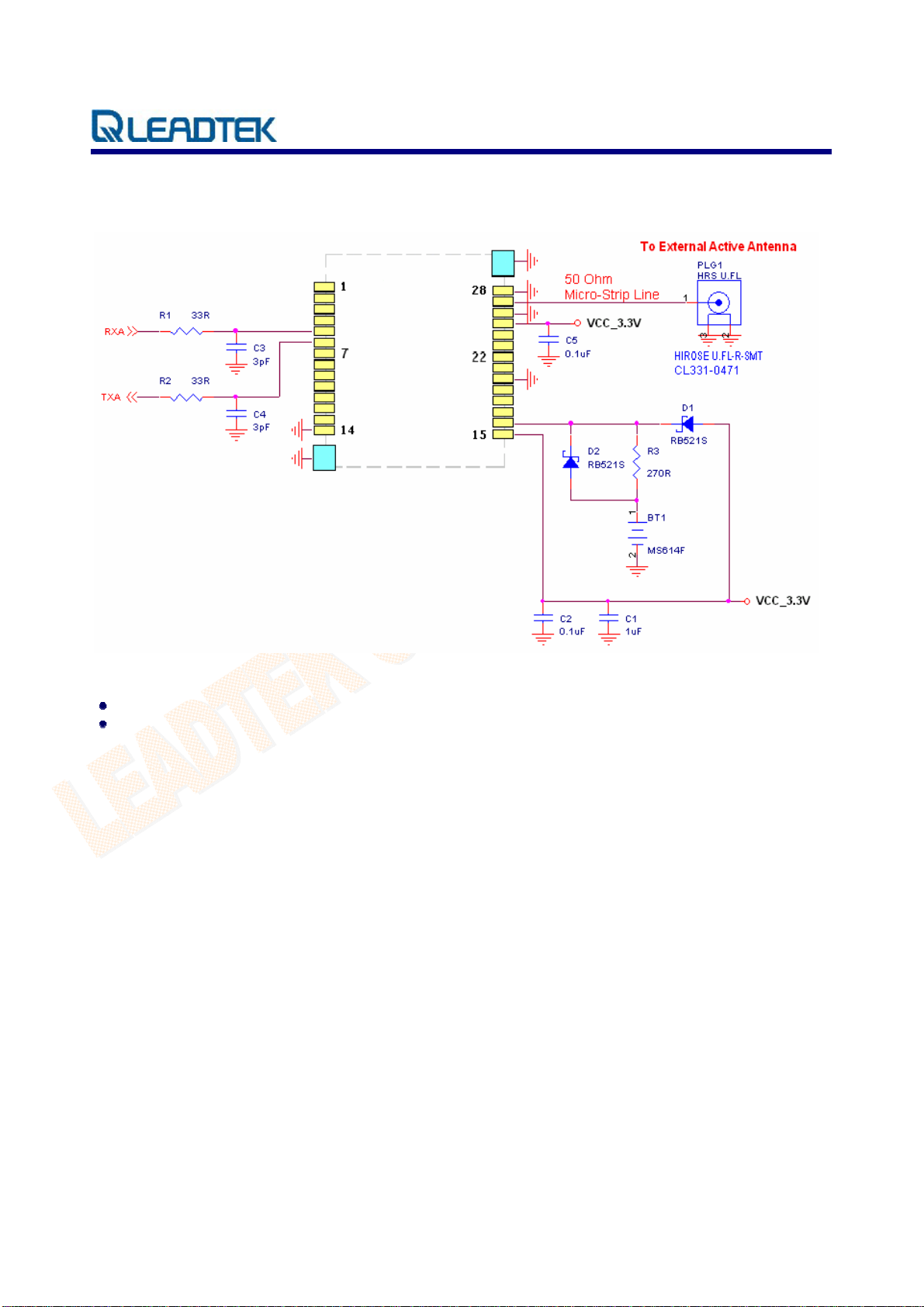
REFERENCE DESIGN ......................................................................................................................5
SOFTWARE ....................................................................................................................................6
ELECTRICAL SPECIFICATIONS.............................................................................................7
BLOCK DIAGRAM ..........................................................................................................................7
INTERFACE SPECIFICATION..................................................................................................7
PHOTOS AND PIN POSITIONS..........................................................................................................7
PIN SETTINGS ................................................................................................................................8
MECHANICAL DIMENSIONS...................................................................................................9
OUTLINE DRAWING .......................................................................................................................9
(Bottom view) .........................................................................................................................10
RECOMMENDED FOOTPRINT..............................................................................................11
AUTOMATED MANUFACTURING COMPONENTS..........................................................12
REEL TAPING SPECIFICATION......................................................................................................12
Tape Reel Drawing.................................................................................................................12
Polystyrene Alloy Taping Specifications................................................................................13
Polystyrene Alloy Taping Drawing........................................................................................13
REFLOW PROFILE ...................................................................................................................14
ROHS COMPLIANCE................................................................................................................15
ORDERING INFORMATION...................................................................................................15
ORDERING INFORMATION...................................................................................................16
GLOSSARY..................................................................................................................................17

LR9548S GPS Module Technical Manual v1.52
© 2006 Leadtek Research Inc. All rights reserved. Page 1/20
Preliminar
y
Confidential - Information is sub
j
ect
t
o chan
g
e without
p
rior notice.
Introduction
The Leadtek LR9548S GPS module is a high sensitivity, low power, Surface Mount Device (SMD).
This 20-channel global positioning system (GPS) receiver is designed for a wide range of OEM
applications and is based on the GPS signal search capabilities of the SiRFstarIII™ single chip
architecture, SiRF’s newest chipset technology. The LR9548S is also pin-to-pin compatible with the
LR9805-III (LR9548) for easier and faster transition.
The LR9548S is designed to allow quick and easy integration into GPS-related applications such as:
PDA, Pocket PC, and other computing devices
Car and Marine Navigation
Fleet Management /Asset Tracking
AVL and Location-Based Services
Hand-Held Device for Personal Positioning and Navigation
Features
Hardware and Software
Based on the high performance features of the SiRFstarIII single chip
Compact module size for easy integration: 24x20x2.9 mm (0.94x0.79x0.11 in).
Fully automatic assembly: reflow solder assembly ready
Hardware compatible with SiRF GSW3.2.0 software
Multiple I/O pins reserved for customizing special user applications
RoHS compliance

LR9548S GPS Module Technical Manual v1.52
© 2006 Leadtek Research Inc. All rights reserved. Page 2/20
Preliminar
y
Confidential - Information is sub
j
ect
t
o chan
g
e without
p
rior notice.
Performance
Cold/Warm/Hot Start Time: 42/38/1 sec. at open sky and stationary environments.
Reacquisition Time: 0.1 second
RF Metal Shield for best performance in noisy environments
Multi-path Mitigation Hardware
Interface
TTL level serial port for GPS communications interface
Protocol: NMEA-0183/SiRF Binary (default NMEA)
Baud Rate: 4800, 9600, 19200, 38400 or 57600 bps (default 4800)
Advantages
Ideal for high volume mass production(Taping reel package)
Cost saving through elimination of RF and board to board digital connectors
Flexible and cost effective hardware design for different application needs
Secure SMD PCB mounting method

LR9548S GPS Module Technical Manual v1.52
© 2006 Leadtek Research Inc. All rights reserved. Page 3/20
Preliminar
y
Confidential - Information is sub
j
ect
t
o chan
g
e without
p
rior notice.
Specifications
Technical Specifications
Feature Item Description
Chipset GSC3f SiRFstarIII single chip
Frequency L1, 1575.42 MHz
C/A code 1.023 MHz chip rate
General
Channels 20
10 meters, 2D RMS
5 meters 2D RMS, WAAS corrected
Position
<5meters(50%), DGPS corrected
Velocity 0.1 meters/second
Accuracy
Time 1 microsecond synchronized to GPS time
Default WGS-84
Datum
Other selectable for other Datum
Reacquisition 0.1 sec., average
Snap start 1 sec., average
Hot start 1 sec., average typical TTFF
Warm start 38 sec., average typical TTFF
Time to First Fix
(TTFF)
(Open Sky &
Stationary
Requirements) Cold start 42 sec., average typical TTFF
Altitude 18,000 meters (60,000 feet) max.
Velocity 515 meters/second (1000 knots) max.
Acceleration 4g, max.
Dynamic
Conditions
Jerk 20 meters/second3, max.
Main power input 3.2 ~ 5.0 VDC input
Power consumption ≈230 mW (continuous mode)
Supply Current ≈70 mA
Power
Backup Power 1.65 ~ 5.0 VDC input.
Electrical interface Two full duplex serial TTL interface.
Serial Port
Protocol messages NMEA-0183@4800 bps (Default)
Level TTL
Pulse duration 1 µs
Time reference At the pulse positive edge.
Time-1PPS
Pulse
Measurement Aligned to GPS second, ±1 microsecond

LR9548S GPS Module Technical Manual v1.52
© 2006 Leadtek Research Inc. All rights reserved. Page 4/20
Preliminar
y
Confidential - Information is sub
j
ect
t
o chan
g
e without
p
rior notice.
Environmental Characteristics
Items Description
Operating temperature range -40 deg. C to +85 deg. C
Storage temperature range -55 deg. C to +100 deg. C
Physical Characteristics
Items Description
Length 24 mm ±0.1mm (0.94in)
Width 20 mm ±0.1mm (0.79 in)
Height 2.9 mm ±0.1mm (0.11 in)
Weight 2.5g
Interface Specifications
Items Description
I/O 28 pin SMD micro package

LR9548S GPS Module Technical Manual v1.52
© 2006 Leadtek Research Inc. All rights reserved. Page 5/20
Preliminar
y
Confidential - Information is sub
j
ect
t
o chan
g
e without
p
rior notice.
Reference Design
All ground pads attach directly to ground plane by way of via.
All components are reference only.

LR9548S GPS Module Technical Manual v1.52
© 2006 Leadtek Research Inc. All rights reserved. Page 6/20
Preliminar
y
Confidential - Information is sub
j
ect
t
o chan
g
e without
p
rior notice.
Software
The firmware used on Leadtek LR9548S module is GSW3.2.0, the SiRF standard GPS software for
SiRFstarIII receivers. Features include:
Excellent sensitivity
High configurability
1 Hz position update rate
Supports use of satellite-based augmentation systems like the US WAAS or European EGNOS
system(Option)
Real-time Operating System (RTOS) friendly
Capable of outputting either NMEA(default) or SiRF proprietary binary protocols
Designed to accept custom user tasks executed on the integrated ARM7TDM1 processor(Option)
Runs in full power operation(default) or optional power saving modes
Default configuration is as follows:
Item Description
Core of firmware SiRF GSW3.2.0
Baud rate 4800, 9600, 19200, 38400 or 57600 bps (default 4800)
Code type NMEA-0183 ASCII
Datum WGS-84
Protocol message GGA(1sec), GSA(5sec), GSV(5sec), RMC(1sec),VTG(1sec)
Output frequency 1 Hz

LR9548S GPS Module Technical Manual v1.52
© 2006 Leadtek Research Inc. All rights reserved. Page 7/20
Preliminar
y
Confidential - Information is sub
j
ect
t
o chan
g
e without
p
rior notice.
Electrical Specifications
Block Diagram
bandpass
filter
LNA
SiRF GSC3f
16.369MHz
TCXO 32.768KHz
Crystal
2.85 VDC
regulator voltage
detector 1.50 VDC
regulator
serial
IO
RFIN
9548S Block Diagram
+ power in + backup battery
antenna
power
Antenna
Interface Specification
Photos and Pin Positions
Pin 15
Pin 28
Pin 1 Pin 14
Serial Number
Model Number

LR9548S GPS Module Technical Manual v1.52
© 2006 Leadtek Research Inc. All rights reserved. Page 8/20
Preliminar
y
Confidential - Information is sub
j
ect
t
o chan
g
e without
p
rior notice.
Pin Settings
PIN Name Type Description
1 FREQ_XFER I If not used, keep floating
2 NC I/O Not connected
3 NC I/O Not connected
4 RXDB I TTL UART Port B input. If not used, keep floating
5 RXDA I TTL UART Port A input
6 TXDA O TTL UART Port A output
7 GPIO5 I/O Reserved, keep floating
8 TIMEMARK I/O 1 PPS output
9 NC I/O Not connected
10 GPIO13 I/O Reserved, keep floating
11 GPIO0 I/O Reserved, keep floating
12 GPIO1 I/O Reserved, keep floating
13 GPIO14 I/O Reserved, keep floating
14 GND PWR Ground
15 VCC_IN PWR 3.2~5.0V DC supply input
16 VSTBY PWR Apply 1.65~5.0V DC for backup RTC & SRAM. If not used,
keep floating
17 BOOTSEL I Pull high for programming mode. If not used, keep floating
18 PBRESN I Reset pin, active low, If not used, keep floating
19 GPIO15 I/O Reserved, keep floating
20 GND PWR Ground
21 NC I/O Not connected
22 NC I/O Not connected
23 TXDB O TTL UART Port B output. If not used, keep floating
24 NC O Not connected
25 ANTPWR PWR Antenna power input
26 GND PWR Ground
27 RFIN I RF Signal input
28 GND PWR Ground

LR9548S GPS Module Technical Manual v1.52
© 2006 Leadtek Research Inc. All rights reserved. Page 9/20
Preliminar
y
Confidential - Information is sub
j
ect
t
o chan
g
e without
p
rior notice.
Mechanical Dimensions
Outline Drawing Tolerance:
Length 24.0 ± 0.4 mm
Width 20.0 ± 0.1 mm
Height 2.90 ± 0.1 mm

LR9548S GPS Module Technical Manual v1.52
© 2006 Leadtek Research Inc. All rights reserved. Page 10/20
Preliminar
y
Confidential - Information is sub
j
ect
t
o chan
g
e without
p
rior notice.
(Bottom view)

LR9548S GPS Module Technical Manual v1.52
© 2006 Leadtek Research Inc. All rights reserved. Page 11/20
Preliminar
y
Confidential - Information is sub
j
ect
t
o chan
g
e without
p
rior notice.
Recommended Footprint
(Unit: mm)

LR9548S GPS Module Technical Manual v1.52
© 2006 Leadtek Research Inc. All rights reserved. Page 12/20
Preliminar
y
Confidential - Information is sub
j
ect
t
o chan
g
e without
p
rior notice.
Automated Manufacturing Components
Reel Taping Specification
Material: Black Conductive High Impact Polystyrene Alloy (UP-6100)
Surface resistivity 109– 1012 Ω/□
Quantity per reel: 1000 pcs./reel
(Unit: mm)
Tape Reel Drawing

LR9548S GPS Module Technical Manual v1.52
© 2006 Leadtek Research Inc. All rights reserved. Page 13/20
Preliminar
y
Confidential - Information is sub
j
ect
t
o chan
g
e without
p
rior notice.
Polystyrene Alloy Taping Specifications
10 sprocket hole pitch cumulative tolerance ±0.20mm
Carrier camber is within 1mm in 250mm
A0 and B0 measured on a plane 0.3mm above the bottom of the pocket
K0 measured from a plane on the inside bottom of the pocket to the top surface of the carrier
Material: black anti-static polystyrene alloy
All dimensions meet EIA-481-3 requirements
Thickness: 0.50±0.05cm
Packing length per 22” reel: 50.0 Meters (1:2)
Component load per 15” reel: 1000 pcs. (SUR-56-3-XL)
Polystyrene Alloy Taping Drawing

LR9548S GPS Module Technical Manual v1.52
© 2006 Leadtek Research Inc. All rights reserved. Page 14/20
Preliminar
y
Confidential - Information is sub
j
ect
t
o chan
g
e without
p
rior notice.
Reflow Profile
High quality, low defect soldering requires identifying the optimum temperature profile for reflowing
the solder paste. To have the correct profile assures components, boards, and solder joints are not
damaged and reliable solder connection is achievable. Profiles are essential for establishing and
maintaining processes. You must be able to repeat the profile to achieve process consistency. The
heating and cooling rise rates must be compatible with the solder paste and components. The amount
of time that the assembly is exposed to certain temperatures must first be defined and then maintained.
The following is an example of a typical thermal profile.

LR9548S GPS Module Technical Manual v1.52
© 2006 Leadtek Research Inc. All rights reserved. Page 15/20
Preliminar
y
Confidential - Information is sub
j
ect
t
o chan
g
e without
p
rior notice.
RoHS Compliance

LR9548S GPS Module Technical Manual v1.52
© 2006 Leadtek Research Inc. All rights reserved. Page 16/20
Preliminar
y
Confidential - Information is sub
j
ect
t
o chan
g
e without
p
rior notice.
Ordering Information
For every order of 1000 pcs , Leadtek will ship the modules with the reel package (shown on page 12).
For order quantities less than 1000 pcs, or when ordering non-whole numbers, Leadtek will snip the
taping and ship the quantity that you request without the reel.

LR9548S GPS Module Technical Manual v1.52
© 2006 Leadtek Research Inc. All rights reserved. Page 17/20
Preliminar
y
Confidential - Information is sub
j
ect
t
o chan
g
e without
p
rior notice.
Glossary
A-GPS
Assisted GPS or AGPS is a technology that uses an assistance server to cut down the time needed to
find the location. Although GPS provides excellent position accuracy, position fixes require lines of
sight to the satellites. In regular GPS networks there are only GPS satellites and GPS receivers.
In A-GPS networks, the receiver, being limited in processing power and normally under less than ideal
locations for position fixing, communicates with the assistance server that has high processing power
and access to a reference network. Although dependent on cellular coverage, AGPS processing is
quicker and more efficient than regular GPS.
API
An application programming interface is a set of definitions of the way one piece of computer software
communicates with another. One of the primary purposes of an API is to provide a set of commonly
used functions, such as to draw windows or icons on the screen. Programmers can then take advantage
of the API by making use of its functionality, saving them the task of programming everything from
scratch.
Baud Rate
Is a measure of the signaling rate, which is the number of changes to the transmission media per
second in a modulated signal.
For Example: 250 baud means that 250 signals are transmitted in one second. If each signal carries 4
bits of information then in each second 1000 bits are transmitted. This is abbreviated as 1000 bit/s.
Dead Reckoning
The process of estimating your position by advancing a known position using course, speed, time and
distance to be traveled. It is figuring out where you will be at a certain time if you hold the speed, time
and course you plan to travel.
Table of contents
Other Leadtek GPS manuals

Leadtek
Leadtek LR9553D User manual

Leadtek
Leadtek GPS 9815 User manual

Leadtek
Leadtek 9553 Series User manual

Leadtek
Leadtek 9553 Series User manual

Leadtek
Leadtek GPS 9537 User manual

Leadtek
Leadtek EVK User manual

Leadtek
Leadtek GPS 9537 User manual

Leadtek
Leadtek 9559X Series User manual

Leadtek
Leadtek LR9580 User manual

Leadtek
Leadtek LR9101 User manual