Lean BDM-0912 User manual

Photos are for reference ONLY.
INSTALLATIONANDOPERATING
INSTRUCTIONS
!WARNING:
·Assembly by an adult.
·This toy is unsuitable for children under 3 years due to
its maximum speed.
·Protective equipment should be worn.Not to be used in
traffic. A reminder that the toy should be used with
caution since skill is required to avoid falls or collisions
causing injury to the user or third parties.
Executive standard:
En71 and En62115
ASTM F963-17
1 2
INSTALLATION INSTRUCTION
In order to improve the quality, we may change part of the structure and
appearance of the product without an advance notice.
Please read the instructions carefully before use, it will tell you the
right operation method and installation steps . Incorrect operation may
damage the product, or even hurt your child. Please keep this instruction
ready and easy to find.
The illustrations in this instruction are used for easier understanding of the
operation method of the product and the product structure. Please note there
may be differences between the pictures and the physical item.
!

34
20
37-96 months

Specification
*The above parameters contain optional features, specific parameters
please refer to our samples.
Name specification
Battery and fuse
Motor
Suitable age
Maxweight
Body size
Speed
Hours of use
Charger
(Recoverable fuse: 5A)
(6V4.5AH*1)
37-96 months
20KG
3-6KM/h
charging8-12hours,using1 to 2 hours
Input:110~240V
Mainmaterial PP(polypropylene) and iron
single drive 6V(Rotational Speed:18000r/min)
Output:DC 6V 500MA
1080*520*720MM
56
Parts List
NO. PICTURE NO. PICTURE
1
1
2
1
1
1
12
1
1
1
3
5
12
4
6
7
9
11
8
10
12
A(Car head) B(Instructions)
C(Handlebar) D(Front fender)
E(Front wheel
suspension shield) F(Music box)
G(Front wheel)
I(Right foot pedal) J(Left foot pedal)
K( Foot pedal hold-open
catch) L(Jockey pulley)
NO. PICTURE NO. PICTURE
*Photos are for reference ONLY.
O(M8 Spanner)
2
1
13 14
N(Steering rod fixed axis)
H(handlebar shield)
1
6
17
16
1
S2(self-tapping screw)
15
2
S3(M5 Screw)
2
18
S4(M5 Nut)
1
19
S1(Spanner)
S5(M5 Spanner)
Installation Steps
78
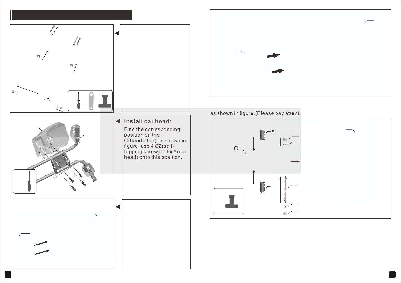
Install car head:
Find the corresponding
position on the
C(handlebar) as shown in
figure, use 4 S2(self-
tapping screw) to fix A(car
head) onto this position.
D
C
1. Install X (Front wheel axle sleeve) into the corresponding position on O
(front wheel)
2. Install O (front wheel) onto the corresponding position on C (handlebar)
as shown in figure.
3. Press R (front axle) through all the front wheel components.
4.Put two S(M8 shims) on both sides of the R (front axle), then fix the both
sides of the front axle by turning the two Q (M8 nuts) in a clockwise
direction. (NO TE: Turn Q(M8 nut) in a anticlockwise direction to
unsnatch it from front axle first).
R
Q
X
X
Q
O
C
Q
Install front fender:
Press and fix the D(front
fender) onto the
C(handlebar) as shown in
figure.
Install front wheel suspension shield:
Press and fix the E(front wheel suspension shield) onto the C(handlebar)
as shown in figure.(Please pay attention to the installing direction )
Install front wheel components:
Preparation for Installation:
1.Take out C (handlebar
components), put H
(handlebar shield) on the
corresponding position as
shown in figure, use S3
(M5 screw) and S4 (M5
nut) to fix H (handlebar
shield) and handlebar
together.(Use S5(M5
spanner)).
2.Use O (M8 spanner) to
loosen and remove Q (M8
nuts), S(M8 shims)、R
(front axle),P (front wheel
axle sleeve) from the
handlebar components.
S3
S3
S4
S4
P
S3
Q
R
H
H
Q
S4
S
S
Q
S
S
E
C
A
C
S2
S2

910
1. Press and fix J (left foot pedal) on the corresponding position as shown
in figure.
2. Press and fix I (right foot pedal) on the corresponding position as shown
in figure.
3. Use K (Foot pedal hold-open catch) to fix two foot pedal.
J
I
K
1. Use screwdriver to remove Q2(self-tapping screw).
2. Take P (music box battery cover) down from F (music box).
1. Place C (handlebar components) on the corresponding position on the
car body as shown in figure.
2. Press N (Steering rod fixed axis) into the hole as shown in figure, use
spanner in a clockwise direction to fix it.
3. Properly connect X and Y (terminals for power supply ).
X
N
NC
YY
Install foot pedal:
Install handlebar components:
Install music board Ⅰ:
1. Use Spanner in a
anticlockwise direction to
unsnatch two Q (M8 nuts)
from the rear axle.
2. Use spanner in a
anticlockwise direction to
unsnatch two R (M6 nuts)
from the jockey pulley
fixed axis.
1. Install L (right and left
jockey pulleys) on the
corresponding position as
shown in figure.
2. Use spanner in a clockwise
direction to fix two R (M6
nuts) on the jockey pulley
fixed axis .
3. Use spanner in a clockwisw
direction to fix two Q (M8
nuts) on the rear axle.
L
L
QQ
RR
Install jockey pulley Ⅰ:
Install jockey pulley Ⅱ:
QR
Q Q
R R
QR
Q2 P
F
Q2

11 12
2.Instructions of the recoverable fuse
When the current exceeds 5 amperes, the recoverable fuse will
automatically cut off the power supply for 5-10seconds, then the current
will be resupplied. (optional)
5A
M1
5A
1. Properly connect X and Y lamp line terminal.
2. Place F (music box) on the corresponding position as shown in figure.
Use two S2(self-tapping screw) to fix F.
3. Properly install two AA (No.5) 1.5V batteries.
4. Use Q2 (self-tapping screw) to fix P (music box battery cover) on the
right position.
- AA +
+ AA -
X
YY
X
F
S2
S2
Q2
Direction for use
Install music board Ⅱ:
1. Instructions for press key
After the driver seated, press the driving switch to drive the car.
relay
drive motor
electric source
charge port
recoverable fuse
drive switch
Simple circuit diagram for single-drive,no-remote-control version
(only has forward function)
S2、
Q2
P
police siren
Starting sound
Light button Horn
Music switch button
Driving switch
Starting sound
Light button Horn
Music switch button

13 14
3.Charging instructions.
When battery power is low,please charge it immediately. The charging port
is on the lower right of the seat. (Note: toys can not be operated in the
charging state. Toys should be charged under adult supervision ) ..
4
5
3
2
1
1. Low battery voltage
2. Electric protection
3. Switch is not reaching the
correct position
4. The Battery connector fell
off or loosened
5. The battery was broken
6. The appliance was
broken
7. The motor was broken
1.Recharge the battery
2.Stop using for a few
minutes
3.Use it according to
the directions
4.Re-plug
5.Go to the maintenance
point
6.Go to the maintenance
point
7.Go to the maintenance
point
1. The Battery connector
fell off or loosened
2. The charger not
connected to the socket
Reconnect
Plug the charger into the
socket
Replace the charger
Distance per
charge is too
short
1. The battery does not have
a full charge
2. The battery is too old
Recharge the battery
Replace the battery
The batteries
get warm and
make a slight
noise during
charge
1. Normal chemical reaction Normal
1. The battery is too old
2. The batteries were
wearing out
Use a new battery
Recharge the battery
lighten the load to less
than 20kg
Drive on a neat pavement
Big noise from
the gear box
Go to the maintenance
point
1.Thegearwasbroken
Shake when the
car is driving
1. Poor wire contact of the
motor
2. Dead point on the motor
To reconnect
Go to the maintenance
point
The car cannot
stop 1. The motor was broken Go to the maintenance point
Connect it follow the
instruction
was
The battery
cannot be
recharged
is
Table of contents
Other Lean Motorized Toy Car manuals

Popular Motorized Toy Car manuals by other brands


Tamiya
Tamiya TOYOTA GR YARIS 51656 Assembly instructions

Harbor Freight Tools
Harbor Freight Tools 62527 owner's manual

Aosom
Aosom 370-189V80 Assembly instruction

Kyosho
Kyosho Mini-Z Racer MR-015 RM Type instruction sheet

Sportwerks
Sportwerks E-RACERS RECOIL Getting started

Kyosho
Kyosho MINI-Z Racer MR-02 RM Type instruction sheet