CRC Battle Axe 3 User manual

8500734 01901
3254 - 2-56 Button Head
4019 - Alum Pivot ball
12772 -
4-40 Thin
Hex Nut
1429 -
4-40 x 7/16”
Flat Head
1209 - Washer
*Note - Sometimes it is helpful to over-tighten the top clamp screws,
then work the ball around by hand, and then loosen the screws so the ball
floats around very free. Do not over-tighten the screws too much or you
could warp the pivot socket.
slightly
1412 - Red Locknut
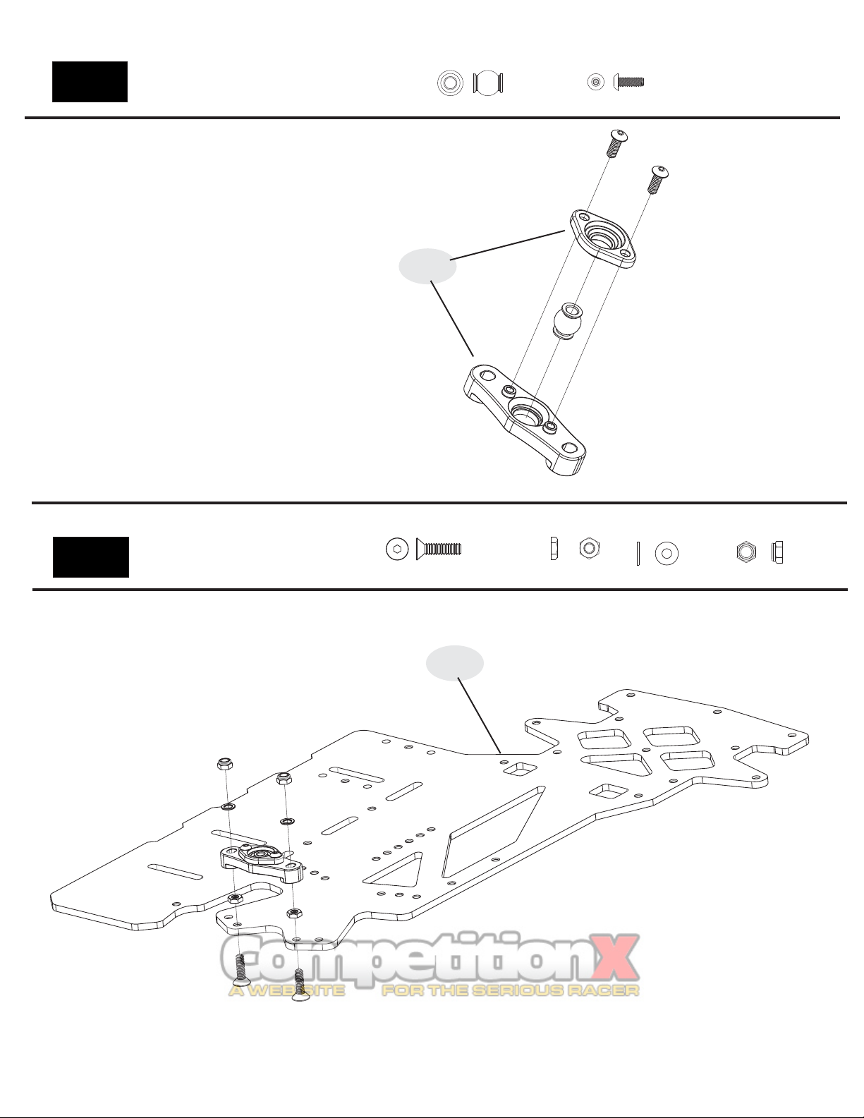
Bag 1
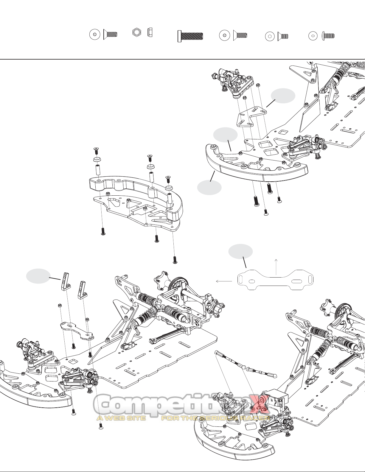
Center Pivot
1
3374 - Center Pivot Socket
Bag 1
Center Pivot
1957 - BA3.0 Chassis Plate
3374
1957

1426 - 4-40 x
5/16” Flat Head 1430 - 4-40 x ½”
Flat Head
One-Piece
Side Links
13615 -
Red Low-
Profile Ball
*NOTE - Before installing, inspect the side links
and you will notice that the screw holes on one
side of the link are larger than the holes on the
other side. Before popping the links on the balls,
be sure that the larger hole faces toward the
outside of the chassis.
Slide the 2-56 button head screws through the
large holes in the outside of the side links, and
then thread them into the small inner holes as
shown in the illustration. Do not tighten these
screws down all the way. Put just enough
tension on them so that there is no play in the
links, but so they pivot freely on the balls. The
car will NOT handle properly if the links are too
tight on the balls!
1 - Be sure the 2 aluminum locknuts on top of the center pivot are slightly loose.
There should be a washer under each alum locknut. Notice that the center pivot
“floats" or moves slightly on the 2 screws. This "floating" allows the links
to "free up". This ensures that the rear pod plate pivots freely on the links
and center pivot ball. This is a crucial step when setting up the Battle Axe.
2 - Snap the 2 links on the balls (done in previous step). They should rock freely on
the pivot balls.
3 - Place the chassis / rear bottom plate assembly on a flat surface. No tires and
no diff on the car! A smooth table or desk should do. Be
sure that the rear bottom plate and chassis are in a
straight line, flat against the table, again, no tires on the
car. Lightly “tap” the chassis and rear pod releasing any
tension in the links. Keep the chassis flat on the table for step 4.
4 - Hold the chassis at the hold point “H” by pressing
the chassis down to the table. Slowly tighten the 2 locknuts that
secure the center pivot assembly. For now, just lightly
snug one side then the other.
5 - Pick up the car and check the pivoting action of
rear lower plate. Rotate the rear plate from side-to-
side. It should move free without binding or "clicking".
If it does not, loosen the pivot locknuts and repeat steps 3+4.
If it rotates smoothly, tighten the locknuts on the center pivot more
securely. Do this by again holding the chassis down to the table at the
hold point “H”. Slowly and carefully, fully tighten the locknuts that hold the center pivot
assembly to the chassis. The handling of the Battle Axe hinges (pun intended!) on the
free movement of this rear plate. Be sure that the rear links and rear plate are free and not binding.
(not the rear pod)
Setting the One-piece links
2
Rotate
Center Pivot
H
3254 - 2-56 Button Head
3280 -
1412 - Red Locknut
Bag 2
1967 - BA3.0 Rear Bottom Plate
1967
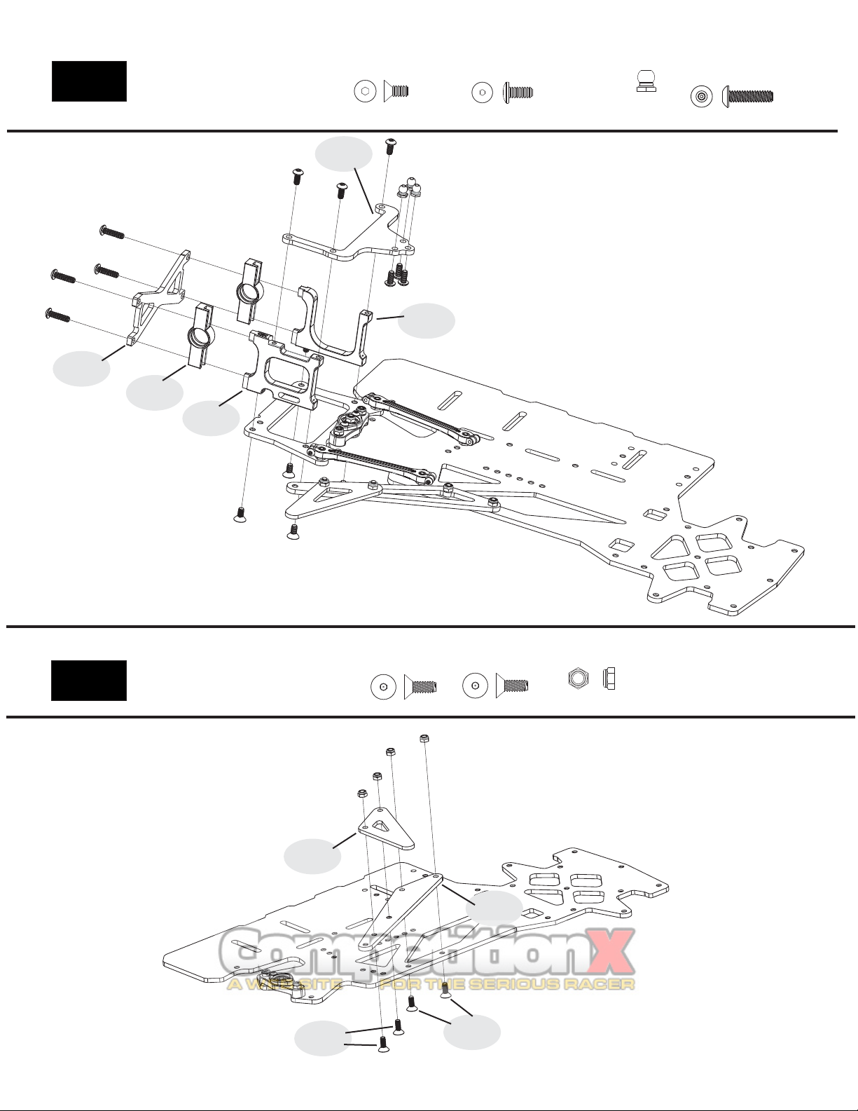
33401 - Motor Plate
3375 - Graphite X-brace
3
1424 - 4-40 x 1/4”
Flat Head
33421 - Left Side Pod Plate
Bag 3
Slider Pod
33411 - Slider Bearing Carrier
33411
33401
33421
3375
1434 - 4-40 x 1/4”
Button Head 13615 -
Red Low-
Profile Ball
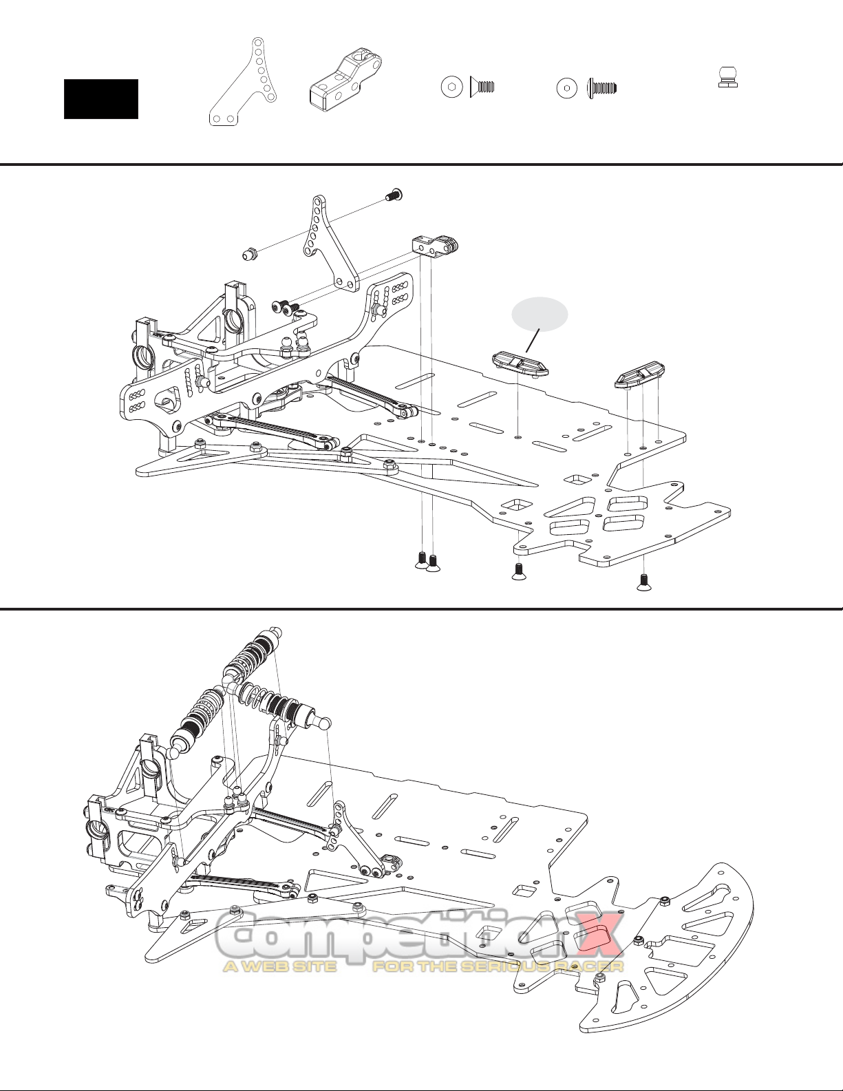
1963 - Rear Top Plate
Bag 4
Shock Tower 1426 - 4-40 x
5/16” FH
1451 - 4-40 x
5/16” FH Red 1412 - Red Locknut
1959 - Nerf Wing
1958 -Shock Tower Mount Wing
1426
1451
1959
1958
1435 - 4-40 x 7/16”
Button Head
1963

4
Bag 4
Shock Tower 1434 - 4-40 x 1/4”
Button Head
1971 - Shock Tower
3355 - Shock Tower Mounts
1424 - 4-40 x 1/4”
Flat Head
1971
3355
13615 -
Red Low-
Profile Ball

5
1 - Thread the spring adjuster nut onto the shock body as shown. *This needs to be installed first or you will not be able to get it on later after the lower endof
the shock is assembled!*
2 - Insert only 1 of the small o-rings into the lower end of the shock body. Next, install the bottom shock plug and tighten the bottom shock cap.
3 - Insert 1 of the small e-clips into the lower groove of the shock shaft. Slide the piston over the shaft until it stops against the e-clip and then secure it in place
with the other e-clip in the end groove.
4 - Put a small dab of the included shock oil on the threads of the shock shaft to lube it and then slide the shock shaft through the bottom end of the shock
carefully so you do not damage the o-ring with the threads on the shock shaft. Pull the shaft all the way through until the piston bottoms out in the shock body.
5 - Wipe off any excess oil from the threads of the shock shaft and then thread on the longer of the 2 included ballcups. *If you need to hold the shaft with pliers,
be sure to wrap a rag around the shaft first so the pliers do not damage the shaft. If there is any damage to the shaft, the sharp edges will damage the o-ring and
cause the shock to leak.
6 - Now with the shaft still fully extended, hold the shock body upright and fill with the included shock oil. Press the shaft in about half way and then return it to
full extension. Look inside the shock and you will notice small air bubbles in the oil. This is the rest of the air that was trapped below the piston. Allow enough
time for the air bubbles to work their way to the surface and pop.
7 - Once satisfied that all of the air is out of the shock, top off with oil and then insert the shock bladder by laying one side into the oil and then rolling your finger
across the top of the bladder to expel any excess air and/or oil.
8 - Insert the flanged ballcup into the upper shock cap and then tighten this down over the shock bladder, being careful to not knock the bladder off its seat and
allowing air to enter the shock. *Double check that the shock is working smoothly through its range of motion and that you can fully compress the shock. Ifit
binds up before being fully compressed, then it has too much oil and you will need to crack the top cap loose and expel a very small amount of oil and re-tighten.
9 - Slide the shock spring over the shock body and keep in place by clicking the spring retainer over the shock shaft and sliding it down over the short ballcup to
keep it in place.
1
5
2.1
2.3
2.2
4
3.1
3.2
7
(Lower groove)
(End groove)
CRC Encore Shock
Bag 5
Side Shocks
3290 -
8.1
8.2
9.2
9.1
Bag 7
Center Shock
&
1946 - Graphite Shock
Mount Plates
1745 - Alum Shock /
Antenna Mount
6
Bag 6
Center Shock
Mount
1424 - 4-40 x 1/4”
Flat Head 1434 - 4-40 x 1/4”
Button Head 13615 -
Red Low-
Profile Ball
3373
3373 - Plastic Battery Position Pieces

3242 - 2-56 x ½” SH
3233 - Plastic Ride Height
Spacers 3, 4, 5mm
3246 - Delrin
Pivot Ball
CRC Pro-Strut
Front End
3242 & 1472 -
2-56 Red Locknut
1429 - 4-40 x 7/16” FH
1 - Pop the delrin pivot ball into the lower arm. Place the arm on a strong table and push the ball in
with the back of screwdriver handle. Or preferably, you can use CRC’s 4279 Ball popper pivot ball
tool. Notice the “lip” of the delrin pivot ball is pointing upward. The diagram to the left represents a
right side lower arm. For the left side, flip the second arm over and be sure the pivot ball is installed
with the lip again facing up.
2 - Once the ball is popped in, insert the black 2-56 clamp screw through the horizontal hole in the
lower arm. Thread the 2-56 red locknut onto the black screw. Tighten the screw slowly continuously
checking the pivot ball. When it begins to bind a bit, back the 2-56 screw off a bit. The ball should
be free to pivot with just a bit of drag. There is no need to have this ball super loose and free, a
slight drag will be just the right amount of clamping force.
Check this fit after a few runs as the ball will wear and require additional clamping force.
Lip
1 - Install the upper A-arm mount with the amount of Dynamic Caster desired. The options are 0, 5 and 10
degrees. The part shown to the right in the diagram is the 5 degree version, however it is most common to use
0 degree blocks for oval racing. The 10 will angle down more toward the front of the car, and the 0 will be
parallel to the chassis. The general thought is the more Dynamic Caster, the more steering the car will have at
corner entry.
2 - Use the 5 mm thick ride height block for 1/10th scale tires. For fine front ride height adjustments, use the
CRC #4262 optional front shim set. This set contains .010, .020 and .030” plastic ride height shims. After
selecting the proper spacer, push the 4-40 x 7/16” screw through the plastic ride height spacer, then through
the lower arm, and then thread the screw into the upper A-arm mount. Be sure NOT to over tighten. Just snug,
you are threading a metal screw into the plastic upper A-arm mount.
Bag F
3247
7
1 - Break the mold tree from the upper A-arm. You can clean up the mold
gates with a hobby knife or rotary tool.
2 - Locate the upper arm hinge pin and slide it into one half of the upper
arm. Locate 3 small caster shims. Push the hinge pin through the 3 shims.
Then continue to push the hinge pin all the way into the upper arm.
3 - Now, install the arm/pin/washer assembly onto the upper arm mount. Put
the hinge pin in the channel. At this point you can set your starting caster
setting by moving these washers forward and back. The position shown to
the left will result in a competitive handling. Moving them to the rear will
increase steering from the center and exit of the corner.
If the fit of the upper arm is tight, trim the upper arm mount SLIGHTLY with a
hobby knife.
4 - Install the upper cap with 4 black 2-56 button head screws. The topper is
the “clamp” for the hinge pin. Be sure to tighten so that any gap is gone,
however, do not tighten beyond that point as damage can occur to the upper
a-arm mount holes.
3245 - Hinge Pin
1253 - Caster Shim 3243 & 3230 -
Upper Cap
3247
3243
3254 - 2-56 Button Head
3247 - CRC Front Arm set
3243 - Upper Arm mnt set-0,5,10
3233
3235 -
Dual Axle 3228 -
King Pin
3234 - Brass
Set Screw
1382 -
E-Clip
3253 -
2-56 SH
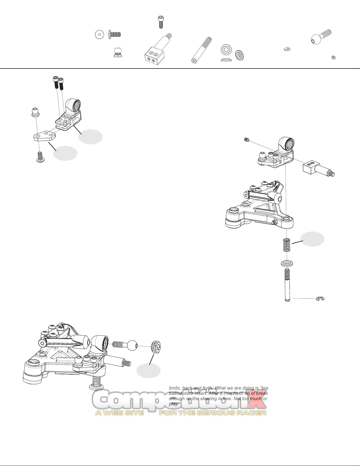
1 - Build up the left and right steering blocks as shown to the left. Start by threading the button head screw through
the steering arm and into the red low profile ball.
2 - Then, slide the steering arm assembly into the steering block, lining up the 2 mounting holes. Using the black 2-56
socket head screws, fasten the arm to the steering block. DO NOT OVER tighten. You will drive the screw through
the steering block, deforming the part.
1 - Push the Dual aluminum axle into the plastic steering block. Push it all the way in firmly.
Notice you can install the axle inline or trailing. Typically, this is installed inline for oval
racing. (as shown to the right) This will increase the steering response as compared to
trailing.
2 - Insert the e-clip into the groove on the end of the King pin. Next, slide the nylon spring
cup all the way down until it rests against the e-clip. Make sure the larger diameter of the
spring cup is against the e-clip and the smaller diameter side faces up. Now slide the spring
down against the spring cup.
3 - Now put your king pin / spring assembly on the end of the Allen key and slide it through
the lower arm pivot ball, & then thread it into the steering block (with the steering block all
the way down against the pivot ball). Thread the king pin in until the spring just touches the
lower arm pivot ball. The preload on the spring can be adjusted with the king pin length.
4 - Once happy with the preload position, lock the king pin with the 4-40 brass set screw
through the back of the steering block.
CRC Pro-Strut
Front End - cont.
3235 - Upper
Pivot Ball
1751 - Steering Arm
8
3287 - Nylon
Spring Cup
1 - Take the upper pivot ball and push it through the steering block and thread
into the upper arm. Thread it in so there are no threads showing.
2 - Take the slotted capture insert and thread it into the steering block. THIS
IS A BIT TRICKY .... as the insert must be fitted at a down angle as shown to
the left. DO NOT try to insert it horizontally into the steering block. It is
actually threaded in at a down angle toward the center of the car.
3 - Tighten this capture insert so that the steering movement is bound and
slow. Yes, we are actually slightly over tightening this piece FOR NOW. With
the steering movement bound from over tightening, move the steering to it’s
limits, back and forth. What we are doing is “breaking in” the upper
ball/capture insert. After a minute or so of break in, loosen the insert just
enough so the steering is free. Not too much or you will induce excessive free
play.
1434 - 4-40 x 1/4”
Button Head
13615 -
Red Low-
Profile Ball
3251
3393
3251
1751
3251 - Steering Block Set
3393 - .50mm
Front Spring
1757
1740
1760
9
Installing the Lower arm to the Chassis
1 - Insert three 4-40 x 5/16” FH screws through the chassis, then through the Front End
Mounting Plate. Secure this with three red locknuts. We recommend starting in the
middle hole of the plates as shown in the pic. This will give you the option to go either
wider or narrower if need be.
2 - Now, secure the front end assembly to the plate using the 8-32 x 5/8” low head front
end screws. Again, we recommend starting in the middle hole, giving you the option to
go longer or shorter.
3 - Repeat these steps for the other side.
4 - For fine ride height adjustments, you can use CRC’s 4262 plastic shim kit (optional).
CRC Pro-Strut
Front End - cont.
17394 - 8-32 x 5/8”
Low Head Screw
1412 - Red Locknut
1426 - 4-40 x
5/16” FH 1451 - 4-40 x
5/16” FH Red
1434 - 4-40 x 1/4”
Button Head
1424 - 4-40 x 1/4”
Flat Head
1715
Front of Car
Left
1753
1740 - Fr. End Mnt Plates 1757 - Graphite Bumper 1760 - Foam Bumper 1753 - Adj Servo Mnt Plate 1715 - Servo Mounts

4201 - Diff Ring 1387 - 1/4” x 3/8”
Plain Bearing Lip
4121 - Diff Spacer 4123 -
Spring Washer 4126 -
Nylon Diff Nut
4732 - 1/4” Shim
1-INSTALL AND GREASE THE DIFF BALLS
Place the spur gear flat on the table in front of you with the side that says “CRC”
facing down. The diff balls will fall into each of the outer ring of holes in the diff
gear, but won’t fall out the other side. Place a small dab of silicone diff grease on
each ball to lube the ball and prevent the balls from falling back out of the holes
during assembly. Use very little!
*(Holding the car on it’s side, with the rear axle pointing upright will ease assembly
of the diff.) Place 1 diff ring, and then a 1/4” x 3/8” plain bearing over the end of
the axle. Align the diff ring so that it notches into the axle flange. Place the
assembled gear with the greased diff balls over the axle and push it down over the
plain bearing. Next, insert the other plain bearing into the back of the diff hub.
Then, align the second diff ring with the notch on the back of the diff hub. *(place a
small dab of the diff grease on the hub first to hold the ring in place.)* Now, slide
the hub, bearing, & diff ring down over the axle. Next, slide a flanged bearing over
the axle and into the front of the diff hub.
2-DIFF ASSEMBLY
Small lip
toward bearing
1
** Balls in outer ring of holes in gear **
1386 - 1/4” x 3/8”
Flanged Bearing
DIFF ASSEMBLY -CONTINUED...
The diff spacer has a small machined lip on one
side, point that lip toward the bearing. Now,
place the spring washer so that the cone points
away from the gear. The outside of the washer
should be against the diff spacer, and the inside
of the washer should be against the diff nut,
which now goes on last. *Be sure the 2 “D” rings
have settled into their notches. Just snug the nut
so the parts stay together on the diff axle.
DON’T over-tighten so the outer diff hub bearing
gets crushed! Correct diff tension needs to be
set with tires on the car.
1376 - 4-40 x 3/8”
Steel Socket Cap
10
3 - Setting the Diff
Once the tires are on: Adjust the diff nut so that the tires spin back and forth freely when holding the
spur gear, but it is very difficult to slip the spur gear with your thumb when holding both tires. Again -
DON’T over-tighten so the outer diff hub bearing gets crushed! Re-check diff tension after the first run.
Bag 8
Differential Axle
Bag 9
Differential
1728
1933
*NOTE -THE 1/4” SHIMS ARE FOR FINE TUNING THE WIDTH OF
THE REAR END.THEY ARE NOT NECESSARY LIKE THE TWO RED
SPACERS SHOWN IN THE DIAGRAM BELOW.
4720 - Axle Spacer-
Xti-2 + 5mm
64072
64080
64088
64096
1228
1925
Dot of
grease
1728 - 1/10 Graphite Axle
1933 - Narrow Left Clamp Hub
1925 - Long Diff Hub
1228 - 3/32 Diff Balls (100)

13783 - 4-40 x 1/8”
Set Screw
11
1462 - 4-40 x 3/8”
Red Socket Cap
4745 -
3/16” Shim
3248 - 3/16” x 5/16”
Flanged Bearing
1 - Use the 4-40 x 3/8” red cap head screws to bolt the rear
wheels to the hubs.
2 - Insert the flanged bearings into the front wheels. Place a
3/16” shim over the axle, then the front wheel, & then a red
locknut last. The front wheels should spin very free. Do not
over-tighten the front wheel nuts so that the bearings are
pinched.
(Tires not included)
1436 - 4-40 x 3/8”
Button Head
1264
Bag 10
Bag 11
1412 - Red Locknut
1264 - Long Body Posts
w/ collars (3 in.)
This manual suits for next models
1
Table of contents
Other CRC Motorized Toy Car manuals


