Leda BIEN-ETRE User manual

BNT0461 - Mars 2015
DOCUMENT A CONSERVER - DOCUMENT TE BEWAREN - DOCUMENT TO BE KEPT
Notice de montage / Montagehandleiding / Instruction manual
BIEN-ÊTRE
DOUCHE FERMEE / GESLOTEN DOUCHERUIMTE / CLOSED SHOWER
NOTICE A CONSERVER PAR L’UTILISATEUR DU PRODUIT
DOCUMENT TO BE KEPT BY THE USER
LEDA : Z.A. Du Bois Gasseau - CS 40252 SAMOREAU - 77215 AVON CEDEX
TEL : 01 60 71 65 65 - FAX : 01 60 71 66 81
INSTRUCTIES TE BEWAREN DOOR DE CONSUMENT
BV DE SPHINX MAASTRICHT - Postbus 1019
NL - 6201 BA Maastricht
Tel. : 00.31.43.35.11.206 - Fax. : 00.31.43.35.11.291
e-mail : [email protected] - www.sphinx.be
Version Angle
Corner version
Versie Hoek

8
61
85
10 x TCL Ø3,5 x 15,9
13 x TCL Ø3,5 x 15,9
2 x TCL Ø4,2 x 15,9
18 x rondelle
sluitring
washer M4
4 x rondelle
sluitring
washer M5
4 x rondelle
sluitring
washer LL5
1 x rondelle
sluitring
washer M4
14
72
16
10
56
3 x TFB Ø3,5 x 12,7
23 x TFB Ø3,5 x 12,7
13
66
8 x cache-vis
schroefafdekkapje
screw cover
24 x cache-vis
schroefafdekkapje
screw cover
17 8 x cheville
plug
screw anchor Ø6
18
3 x Equerre
haak
bracket
11
8 x TF Ø 4,8 x 31,7
12
6 x TCL Ø3,5 x 25,4
31 6 x Joint caoutchouc
rubber afdichting
rubber seal
34
46 1 x foret
boor
drill bit Ø 2,5
2 x joint fibre
vezel dichting
fiber seal 1/2
9
73
10 x TFB Ø3,5 x 15,9
1 x TFB Ø3,5 x 15,9
Le logo de la marque de votre
produit à placer de préférence
sur une partie plane et vitrée.
The logo of the brand of your
product to be rather placed on
a flat and glazed part.
Het zelfklevend logo van het merk
van uw product, bij voorkeur
te kleven op een glasoppervlak.
39
74
2 x écrou
moet
nut Hm4
4ou6 x écrou
moet
nut Hm4
4 x écrou
moet
nut m5
42
57
4 x entretoise
dwarsverbinding
glass protection
1 x entretoise
dwarsverbinding
glass protection
2 x entretoise
dwarsverbinding
glass protection
2 x entretoise
dwarsverbinding
glass protection
4 x entretoise Ø5,2
dwarsverbinding
protection
38
2 x TCL Ø 4 x 25
CONFORT
CONFORT
CONFORT
10 x rondelle canon épaulée
Onderlegring
canon washer
44
62
8 x TCL Ø3,5 x 31,7
81
2 x cache vis
schroef afdekkapje
screw cover
2 x rondelle
sluitring
washer
59
58
2 x rondelle Z4
sluitring
washer
60
4ou6 x Tchc M4x16
2 x Tchc M5x25
4 x Tchc M5x40
75
48c
41a 41b 41d
41e
41c
83
2 x bouchon
dop
cap
82 8 x obturateur
sluiter
shutter
86 Guide-vis
Schroefgeleider
Screw guide

1040
1090
Sol
Vloer
Ground
1320
Douchette main /
Handdouche /
Handshower
Barre de douche /
Douchestang /
Raiser rail
Porte savon /
Zeepschaal /
Soap holder
Mitigeur /
Kraan /
Mixer
Flexible /
Doucheslang /
Hose
Eau chaude/eau froide
Alimentations verticales
dans cette zone (1/2 gaz male)
Vertikale aanvoeren in
deze zone (1/2" mannelijk)
Hot water/Cold water
Vertical water inflow in this
zone (1/2" male)
Warm water/koud water
1990
Sol
Vloer
Ground
Douchette main /
Handdouche /
Handshower
Barre de douche /
Douchestang /
Raiser rail
Mitigeur /
Kraan /
Mixer
Flexible /
Doucheslang /
Hose
1990
AVANTAGECONFORT
BB
DD
AA
CC
OU
OF
OR
G(Passage)
(Instap)
(Door way)
G(Passage)
(Instap)
(Door way)
E (Partie fixe)
(Vast gedeelte)
(fixed part)
E (Partie fixe)
(Vast gedeelte)
(fixed part)
H
J
125
3
Option tablier aluminium laqué blanc /
Optie voorpaneel aluminium wit gelakt /
White aluminium carter option
30 à 50 selon modèle /
Volgens model /
Depending of the model
Sol/Vloer/Ground
Version AVANTAGE maxi 2370
80mm
80mm
GÒÖ ÑŌŒÒŎŌŒA (mm) B (mm) C (mm) D (mm) E (mm) G (mm) H (mm) J (mm)
120x90cm 1210 910 600 185 630 500 450 700
140x90cm 1410 910 700 185 730 600 450 700
160x90cm 1610 910 800 185 830 700 450 700

OUTILS / GEREEDSCHAP / TOOLS
Niveau/Waterpas/Level
Chiffon/Doek/Cloth
Pince multiprises/Combinatietang/Adjustable pliers
Perceuse/Boormachine/Drill
Tournevis cruciforme pozidrive/
Platte kruiskopschroevendraaier/
Cross-head screwdriver
Foret/Boortjes/Drill bit Ø2 - Ø4 - Ø5 - Ø6 (Ø2,5 fourni/meegeleverd/provided)
Cutter
Mètre à ruban/Meetlint/Tape measure
Clé mâle de 2,5mm/Stiftsleutel van 2,5mm/2,5mm male wrench
Clé mâle de 3mm/Stiftsleutel van 3mm/3mm male wrench
Clé mâle de 10mm/Stiftsleutel van 10mm/10mm male wrench
Scie
Maillet/Houten hamer/Mallet
Pince coupante/Kniptang/Cutting plier
INSTALLATION HYDRAULIQUE / HYDRAULISCHE INSTALLATIE / HYDRAULIC SYSTEM
- La robinetterie est prévue pour fonctionner sur toutes sortes d’installation.
Pression maximale : 5 bars. Au-dessus, poser un réducteur de pression.
Consommation en douchage normal : 19 litres à 3 bars (sans joint limiteur de débit).
Dans le cas où l’eau contient des impuretés, nous vous conseillons d’installer un
filtre.
Vidage : utilisation d’un tube ø40 mm.
L’espace douche est équipé d’une bonde.
- Het kraanwerk is ontworpen om te functioneren op alle soorten installaties.
Maximum druk : 5 bar. Wanneer de druk meer bedraagt, moet u een drukregelaar plaatsen.
Verbruik bij normaal douchegebruik : 19 liter bij 3 bar (zonder debietbegrenzer).
Als het water onzuiverheden bevat, raden wij u aan om een filter te installeren.
Afvoer : gebruik van een flexibele buis Ø 40.
De doucheruimte is uitgerust met een afvoerstop.
- The faucets are made to work on any kind of system.
Maximal pressure: 5 bars. Above, put a pressure reducer.
Consumption when normal showering: 19 liters at 3 bars (without flow limiter seal).
In case the water contains impurities, we recommend you to install a filter.
Outlet: use a ø40 mm tube.
The shower is equipped with a drain trap.
Cet espace douche doit obligatoirement être installé par du personnel qualifié.
- Le receveur doit obligatoirement être posé sur une surface plane et horizontale.
- Pour la pose de la bonde ne pas utiliser de mastic ou de colle.
- Suivre attentivement la notice de montage.
- Prévoir si possible des robinets d’arrêt sur les alimentations d’eau chaude et
d’eau froide.
- Avant la mise en service définitive, vérifier l’étanchéité du circuit d’eau
(éventuellement resserrer modérément tous les raccords).
Deze doucheruimte moet geplaatst worden door een vakman.
- De douchebak moet op een vlak en horizontaal oppervlak geplaatst worden.
- Geen mastiek of lijm gebruiken voor de plaatsing van de sifon.
- De montage-instructies nauwgezet volgen.
- Plaats indien mogelijk stopkranen op warm en koud watertoevoer.
- Vóór definitieve ingebruikname, watercircuit controleren op lekkage
(eventueel alle aansluitingen licht aandraaien).
This shower cabin must necessarily be installed by a specialized person.
- The shower tray must necessarily be put on a flat and horizontal surface.
- For the installation of the drain trap, do not use mastic or glue.
- Follow attentively the assembly notes.
- If possible, plan a stop valve on warm and cold water inflows.
- Before the taking into use, check the waterproofness of the water circuit (eventually tight up moderately all the connectors).
CONSEILS DE POSE / TIPS VOOR MONTAGE / INSTALLATION ADVICES

1) Version posée avec tablier / Opbouwversie / Lay-on version
2) Version posée sur socle / Opbouwversie / Lay-on version
3) Version encastrée / Inbouwversie / Semi-recessed version
MONTAGE DES PIEDS / PLAATSING VAN DE POTEN / FEET SET-UP
Pose du receveur / installatie van de douchebak / Shower tray installation
CHOIX : 3 VERSIONS / KEUZE : 3 VERSIES / CHOICE : 3 VERSIONS
Bonde encastrée /
ingebouwde sifon /
Built-in plug
Bonde et cuve encastrées /
Ingebouwde sifon en douchebak /
Built-in plug and tank
A

DISPOSITION DES PIEDS / SCHIKKING VAN DE POTEN / FEET LAYOUT
1)Version posée avec tablier / Opbouwversie / Lay-on version
a b
Ø M4X12
Nettoyer et passer un coup
de papier de verre avant
l’adhésivage du plot
Reinigen en met glaspapier
licht afschuren alvorens
contactblokje te kleven
Clean and use sandpaper before
sticking the pot up.
125
3
125
II
I
L32AC001
(jeu de pieds /
set poten /
feet set)
a
b

2)Version posée sur socle / Opbouwversie / Lay-on version
Prévoir l ’encastrement de la bonde
dans le sol, ainsi que l ’évacuation. /
Inbouw van sifon in de grond voorzien,
alsook de afvoer. /
Plan to build the plug and drainage
in the ground
300
300
Axe receveur
As douchebak
Tray’s axis
Raccorder la bonde
Sifon aansluiten
Fit the drain trap in.
Axe du receveur
As van de douchebak
Tray axis
Ø40
MUR FINI
AFGEWERKTE MUUR
FINISHED WALL
mortier maigre / dunne mortel / thin mortar
Calage env. 10x10cm, (brique,
parpaing, béton cellulaire,..)
Steun ong. 10x10cm,
(baksteen, bindsteen, gasbeton,...)
Welding about 10x10cm (brick, breeze-
block, cellular concrete,...)
5585
SOL
VLOER
FLOOR
140
Cadre /
Kader /
Frame
NOTA: Le contact de plâtre ou de colle pour plaques ou carreaux de plâtre avec la sous-face du
receveur est à proscrire.
NOTA: Het contact tussen gips of lijm voor gipstegels met de douchebak moet vermeden worden.
NOTE: The contact between the plaster or glue for sheetrock and the underneath surface of the
tray has to be absolutely avoided.
Maçonnerie / Metselwerk / Masonery
8 x TFB Ø3,5 x 12,7
Rep Qté Désignation 120 x 90 140 x 90 code 160 x 90
1 2 Traverse 900 L12AB5R0401 L12AB5R0501 L12AB5R0601
2 2 Traverse 120, 140 ou 160 L12AB5R0401 L12AB5R0501 L12AB5R0601
3 4 Pièce d'Angle
4 8 Vis TFB Ø3,5 x 12,7 T0SA081
T0SA099BL

VERSION RECEVEUR SUR SOCLE OU ENCASTRÉ
INBOUWVERSIE
INSTRUCTIONS DE POSE DES RECEVEURS ENCASTRES
MONTAGEHANDLEIDING VOOR INBOUWDOUCHEBAKKEN
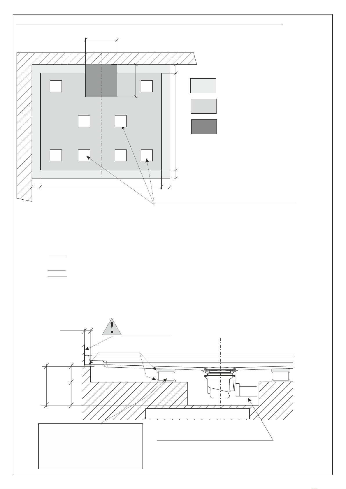
- Dans tous les cas d’installation, il est nécessaire de supporter le receveur sous le fond
et sous sa périphérie.
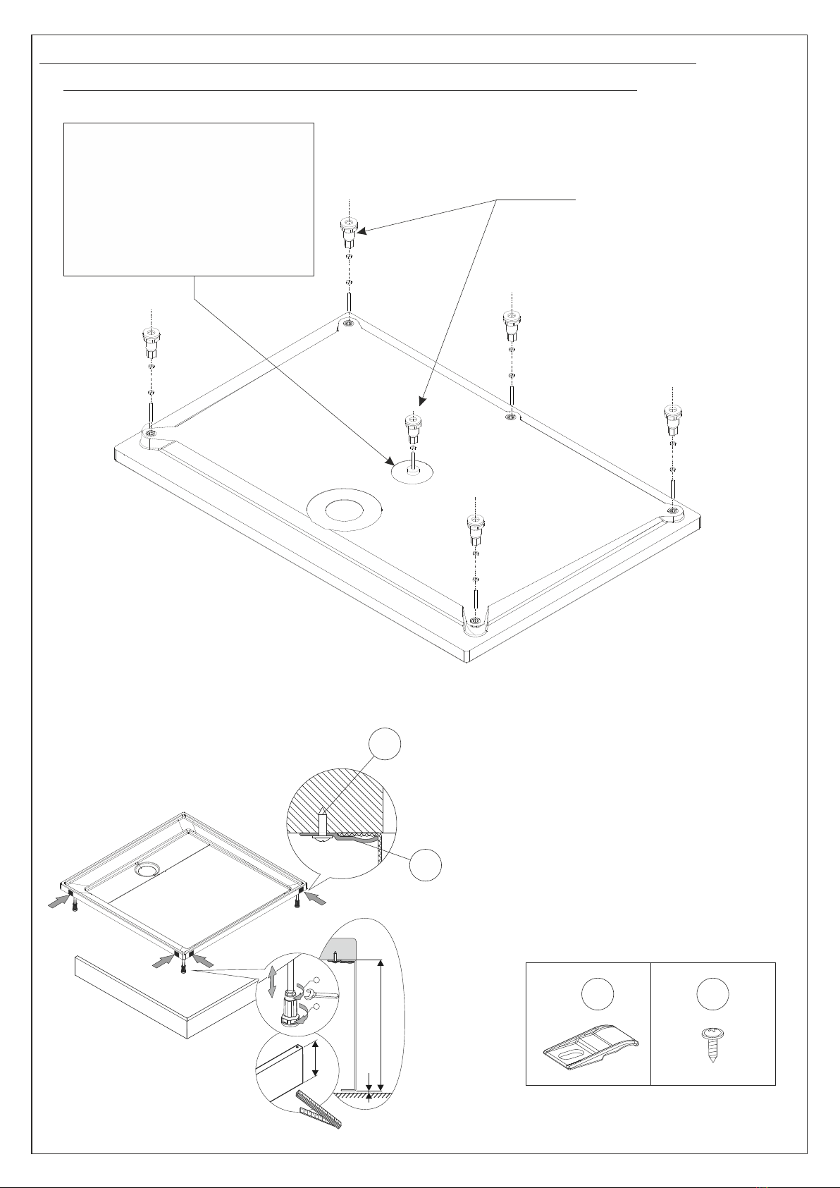
- Régler la hauteur et le niveau de la périphérie du receveur.
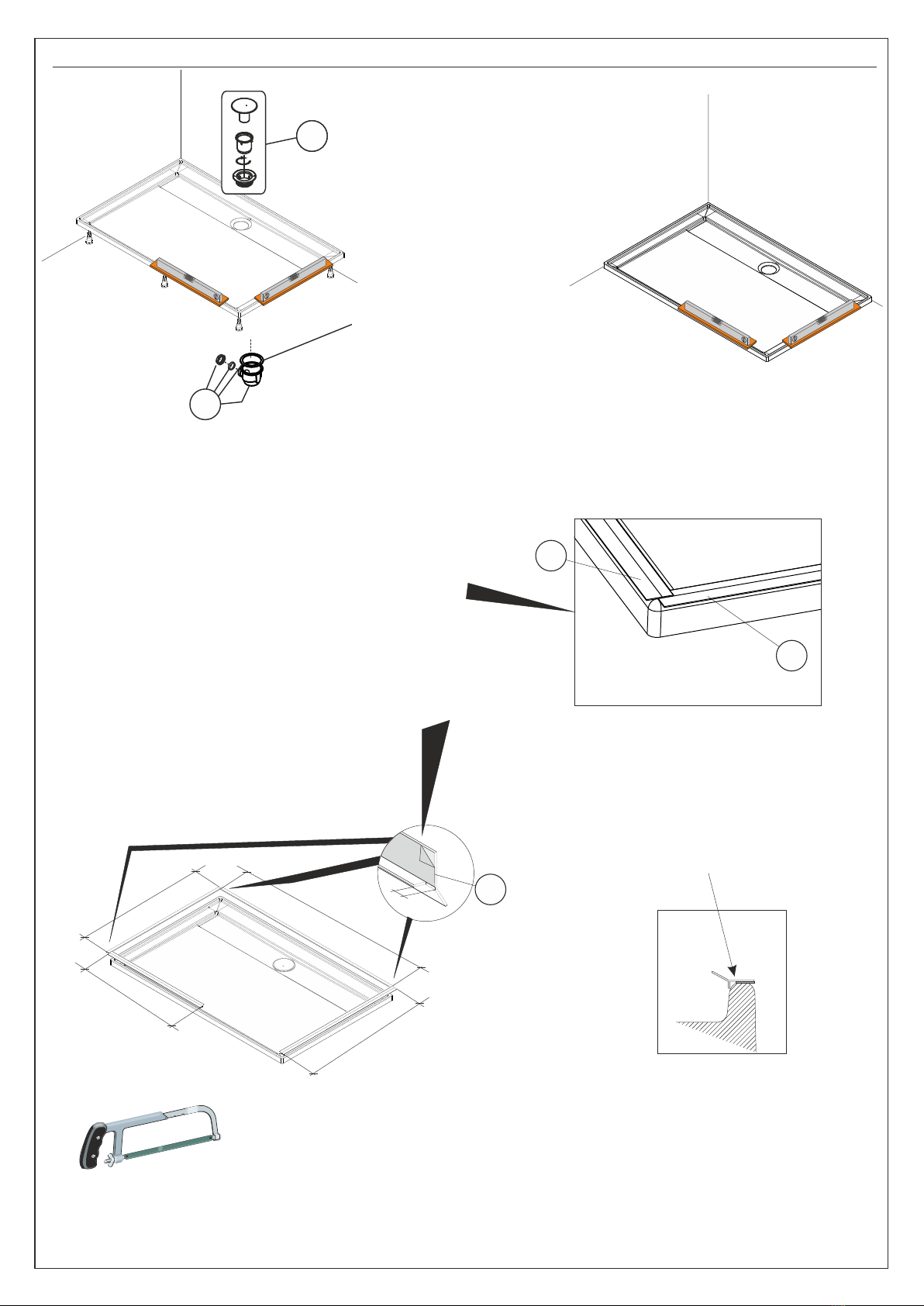
- En aucun cas, le receveur ne doit subir de modification (sciage, découpe de renfort...)
- Protéger le receveur pendant toute la durée des travaux contre toute agression (brûlure,
choc, rayure, peinture, décapant...)
SUPPORTAGE DU FOND
- Le supportage du fond doit être assuré :
au minimum, par 4 supports rigides (brique, parpaing, béton cellulaire...) pour
un receveur de 90x90 et plus pour un receveur de dimension supérieure, ayant chacun
une surface d’appui d’environ 10x10cm à répartir uniformément, solidarisés au receveur
et scellés sur la chape / dalle.
- Le contact direct de produits à prise hydraulique avec la sous face du receveur autres que
du mortier maigre est à proscrire.
LE SUPPORTAGE PERIPHERIQUE EST OBLIGATOIRE
- In alle gevallen dient bij installatie de bodem en de randen van de douchebak
ondersteund te worden.
- Hoogte van de douchebak regelen en waterpas maken.
- In geen enkel geval mogen wijzigingen aan de douchebak aangebracht
worden (afzagen, uitsnijden,...).
- Bescherm de douchebak gedurende de hele periode van de werken tegen elke vorm
van agressie (verbranding, schokken, krassen, verf, bijtmiddelen,...).
ONDERSTEUNING VAN DE BODEM VAN DE DOUCHEBAK
- De ondersteuning van de bodem van de douchebak moet gebeuren door :
minimum 4 harde steunpunten (bakstenen, blokken, gasbeton,...)
voor een douchebak van 90x90 en meer steunpunten voor grotere douchebakken.
Elk steunpunt moet ongeveer een steunoppervlak van 10x10 cm bedragen, gelijkmatig
verdeeld worden, aansluiten onder de douchebak en vastgemetseld worden
aan de deklaag/vloerstenen.
- Het direct contact van de bodem van de douchebak met waterhoudende producten
ander dan dunne mortel, is verboden.
DE ONDERSTEUNING VAN DE RANDEN IS VERPLICHT
SEMI-RECESSED VERSION
INSTALLATION INSTRUCTIONS FOR SEMI-RECESSED SHOWER TRAYS
- For any installation typology it is necessary a support at the bottom of the shower tray
and on all the perimeter.
- Regulate the height and the planarity of the shower tray rim.
- It is absolutely forbidden to modify the shower tray (to saw, to cut the reinforces, …)
- Protect the shower tray against the aggressions during all the installation phase
(burning, shocks, paints, scale removers, ..)
SUPPORT OF THE SHOWER TRAY BOTTOM
- Shower tray bottom must be supported by:
at least, 4 rigid supports (bricks or blocks of cement, cellular concrete, ..)
for a 90x90 shower tray, or in greater quantity for bigger shower trays, each one with a
surface of about 10x10cm, uniformly distributed, integrated to the shower tray and inserted
in the slab.
- Hydraulic setting products direct contact other than light mortar has to be avoided.
A PERIPHERAL SUPPORT IS COMPULSORY

20
20
MUR / MUUR / WALL
300
Axe du receveur
300
20
20
20
6080
140
Calage env. 10x10cm, (brique,
parpaing, béton cellulaire,..)
Steun ong. 10x10cm,
(baksteen, bindsteen, gasbeton,...)
Wedging:bricks or blocks of cement,
cellular concrete,...
Ø40
Raccorder la bonde
Sifon aansluiten
Fit the drain trap in.
Position des calages à effectuer
Positie van de aan te brengen steuntjes
Wedges position
Epargne receveur Profondeur = 60
Uitsparing douchebak Diepte = 60
Shower tray housing depth = 60
Epargne bonde Profondeur = 140
Uitsparing afvoer Diepte = 140
Drain trap housing depth = 140
Supportage périphérique
Ondersteuning randen
Peripheral support
Dimension receveur -40mm
Afmeting douchebak -40mm
Shower tray dimension -40mm
Dimension receveur -40mm
Afmeting douchebak -40mm
Shower tray dimension -40mm
Sol
Vloer
Floor
3) Version encastrée / Inbouwversie / Semi-recessed version
mortier maigre / dunne mortel / thin mortar
Axe du receveur
As van de douchebak
Tray axis
Maçonnerie / Metselwerk / Masonery
NOTA: Le contact de plâtre ou de colle pour plaques ou carreaux de plâtre avec la sous-face du
receveur est à proscrire.
NOTA: Het contact tussen gips of lijm voor gipstegels met de douchebak moet vermeden worden.
NOTE: The contact between the plaster or glue for sheetrock and the underneath surface of the
tray has to be absolutely avoided.
MUR FINI
AFGEWERKTE MUUR
FINISHED WALL

Mise en place du receveur / Plaatsing van de douchebak / Tray set-up
21
Faire une encoche de 10mm à la pince coupante
pour permettre le recouvrement des joints
Maak met de kniptang een inkeping van 10mm
om de overlapping van de afdichtingen toe te laten.
Using a pair of sharp pliers, cut a 10mm notch making
the seal to fit
21
10mm
21
Pour un bon adhésivage,
nettoyer le bord du receveur
Voor een goede hechting,
boord van de douchebak reinigen.
To ensure proper adhesion, clean
the edge of the showertray plateform.
A
X
120x90 : X=1170 Y=870 A=560
140x90 : X=1370 Y=870 A=660
160x90 : X=1570 Y=870 A=760
Vérifier les niveaux, affiner
les réglages si nécessaire.
Niveau controleren, regeling
afstellen indien nodig.
Check the levels and do the
necessary adjustments.
Y
Y
2
2
Joint en dessous
du receveur
Afdichting onder
de douchebak
Shower platform
under seal
- Ne pas utiliser de
mastic ou de colle
- Geen mastiek of
lijm gebruiken
- Do not use putty
or adhesive
Protéger la cuve du receveur lors du montage /
Bescherm de douchebak tijdens de montage /
Protect the tray ’s tank during assembly

A
B
C
B
C
E
14
39
44
38
4 x rondelle M4
sluitring
washer
2 x écrou Ø4
moer
nut
2 x TCL Ø 4 x 25
36
38
37
35
23 25
26
39
14
44
14
27
2 x entretoise
dwarsverbinding
glass protection
EQUIPEMENT DU PANNEAU ROBINETTERIE CONFORT
UITRUSTING WAND MET KRAANWERK CONFORT
CONFORT SPROUTS PANEL EQUIPMENT
Positionner les accessoires (A-B-C) sur la barre (E) en respectant le croquis ci-contre.
Positionner l’ensemble sur le vitrage et fixer en respectant le croquis ci-dessous.
Cliper les cabochons (B) sur les embases (C)
Accessoires (A-B-C) op de stang (E)plaatsen zoals op de tekening hiernaast.
Op glaswand plaatsen volgens de tekening hieronder.
Beschermingskapjes (B) op steun (C) vastclippen.
Set up accessories (A-B-C) on the bar (E) following opposite draw
Set up the whole on the panel following here below draw
Clip the covers (B) on the spuds (C)
2 x rondelle canon épaulée
onderlegring
canon washer
28
30
29
43
31
31
32
34
45
33
27
24
B-1

36
35
EQUIPEMENT DU PANNEAU ROBINETTERIE AVANTAGE
UITRUISTING WAND MET KRAANWERK AVANTAGE
AVANTAGE SPROUTS PANEL EQUIPMENT
23
24
25
27
38
37
39
39
44
34
45
30
43
31
31
32
26
33
Clé de 4
Sleutel van 4
Key of 4
Clé de 10
Sleutel van 10
Key of 10
B-2
28

Assemblage des panneaux du module (suite)
Assemblage van de achterwanden (vervolg)
Unit panels set up
C
1
40
7
a
a
b
48a
48b
48b
48c
2 x TCL Ø4,2 x 15,9
85
86 Guide-vis
Schroefgeleider
Screw guide
85

Abaisser le siège, pousser la clavette p o ur le verrouiller
Lower the seat, push the lockin g pin to lock it
De stoel naar beneden brengen, duwen de
spie om de stoel blokkeren
1
Oter la platine murale du siège
Remove the wall mount from the seat
Het muurafsluiplaatje van de stoel wegnemen
Visser afin de rendre le système indémontable sans outils
Screw in so the system cannot be d i s mantled without tools
Vastschroeven om het systeem niet demonteerbaar
te maken zonder gereedschap
2 3
4
5
2
3
41a 41b 41d
41e
41c

10 x Rondelle M4
sluitring
washer
14 16
8
6
10 x rondelle canon épaulée
onderlegring
canon washer
6
7 8
Fixer provisoirement le panneau
démontable à l’aide de 4 vis
Afneembaar paneel voorlopig
bevestigen met behulp van
4 schroeven
Emporally fasten the removable
panel using 4 screw
9
4 x TFB Ø3,5 x 15,9
4
14
16 4 3
3
OU
8
6
10 x TCL Ø3,5 x 15,9
40 40
3
9
5

9
755
778
Longueur
Longueur
160x90
160x90
140x90
140x90
120x90
120x90
65
51
68
58 60 61
59
62
61
61
61 82 61
80
12 x TCL Ø3,5 x 15,9
8 x TCL Ø3,5 x 31,7
61
80
81
76
66
56
71
79
77
70
87
78
83
50
69
81
73
1 x TFB Ø3,5 x 15,9
66 56
IMPERATIF :
UTILISER L’ENTRETOISE (62)
LORS DU CONTRE PERCAGE
DU VERRE
NOODZAKELIJK :
GEBRUIK DE
DWARSVERBINDING (62)
BIJ HET TEGENBOREN
VAN HET GLAS
IMPRATIVE :
USE THE GLASS PROTECTION
WHEN DRILLING
Ø2,5
62
1 x rondelle
sluitring
washer M4
72
66 5 x cache-vis
schroefafdekkapje
screw cover
1 x entretoise
dwarsverbinding
glass protection
57
83
2 x bouchon
dop
cap
Positionnement du joint
56
4 x TFB Ø3,5 x 12,7
82 8 x obturateur
sluiter
shutter
2 x obturateur
sluiter
shutter
2 x cache vis
schroef afdekkapje
screw cover
2 x rondelle
sluitring
washer
59
58
2 x rondelle Z4
sluitring
washer
60
A monter
en dernier
84
2
2
1
1

3 x TFB Ø3,5 x 12,7
10 x TFB Ø3,5 x 12,7
3 x cache-vis
schroefafdekkapje
screw cover
10 x cache-vis
schroefafdekkapje
screw cover
13
66
10
56
56
66
Ø2,5
Ø2,5
13
10
x3
x3
x5
56
66
10
48a
48b
48b

a
11
4 x cheville Ø6
plug Ø6
screw anchor
17
17
14
14
12
12 42
42
4 x TF Ø4,8 x 31,7
11
350
1600
4 x entretoise
dwarsverbinding
glass protection
Fixer l’équerre de
fixation de la colonne.
Bedieningskolom
bevestigen met de
haak.
Fasten the column
fixing bracket
Retirer le panneau démontable
Afneembaar paneel verwijderen
Take out removable panel
Eventuellement recouper
les équerres.
Haken eventueel afzagen
Eventually cut the brackets
for adjustment.
Ø5 Ø4
4 x rondelle
sluitring
washer M4
4 x TCL Ø3,5 x 25,4
Ø2,5
Mur
Muur
Ø6
c
b
b19
11

Effectuer le raccordement
des arrivées d’eau.
Watertoevoer aansluiten
Connect water intakes
Remettre le panneau démontable en
place et le fixer entièrement.
Het afneembaar paneel terugplaatsen
en volledig vastschroeven.
Put back in place the removable panel
and permanently fasten it.
Couper et Clipper les fileurs
Afwerkingsprofielen vastclippen
Cut and Fit the spacer in
a
b
b c
c
1205
1205
1205
735
735
735
a
9
9
9
10 x TFB Ø3,5 x 15,9
12
13
20
20
Ø4
Percer
Boren
Drill
18
4 x TF Ø4,8 x 31,7
2 x TCL Ø3,5 x 25,4
4 x cheville Ø6
plug Ø6
17
11
12
18
11
MUR
MUUR
WALL
+
Ø6
12
screw anchor Ø6

74
4 x écrou
moet
nut Hm4
4 x Tchc M4x16
75
Ø2,5
50
14
1 x rondelle
sluitring
washer M4
72
73
1 x TFB Ø3,5 x 15,9
57 1 x entretoise
dwarsverbinding
glass protection
67
55
63
1
2
3
53
Tête de la vis de réglage vers le bas.
Kop van de regelschroef naar beneden
Adjust screw head down
54
1
35
64
75
74
73
66
72
57
1
2
This manual suits for next models
2
Table of contents
Popular Bathroom Fixture manuals by other brands

Jacob Delafon
Jacob Delafon PANOLUX user manual

Geberit
Geberit IDO Glow 600 Operating and maintenance instruction

Hans Grohe
Hans Grohe Showerpipe Puro Instructions for use/assembly instructions

Whalen
Whalen LWS60HBVW Assembly instructions

Santec
Santec HANA 4164TR Series quick start guide

Pegasus
Pegasus 873-9004 Use and care guide

Roltechnik
Roltechnik INTEGRO installation instructions

AQUALUX
AQUALUX Aqua 3 quick start guide

Stella
Stella ROMA Installation & user guide

Pulse Shower Spas
Pulse Shower Spas 1089-BN owner's manual

Axor
Axor Starck 10929007 Instructions for use/assembly instructions

Schell
Schell COMPACT VERONA 01 122 06 99 Mounting and installation instructions