Page 18
Worldwide Sales Offices.
UK and Europe.
Ledion Ltd,
Westfield, Rear Of 24-26 Leicester Road,
Blaby,
Leicester.
LE8 4GQ.
TEL: +44 (0) 1162 788078 Fax +44 (0) 1162 771286
USA / Canada.
Ledion Inc,
1930-1 North Commerce Parkway,
Weston,
Florida.
FL 33326.
TEL: +1 954-389-8866 Fax +1 954-389-5747
Asia.
Ledion Asia,
Hua An Building Suite 17D
Chang Qing West Road
Chang An Town, Dong Guan City
Guang Dong, China 523423
Tel: +86 769 553 5337 Fax: +86 769 553 5465
Page 3
Welcome
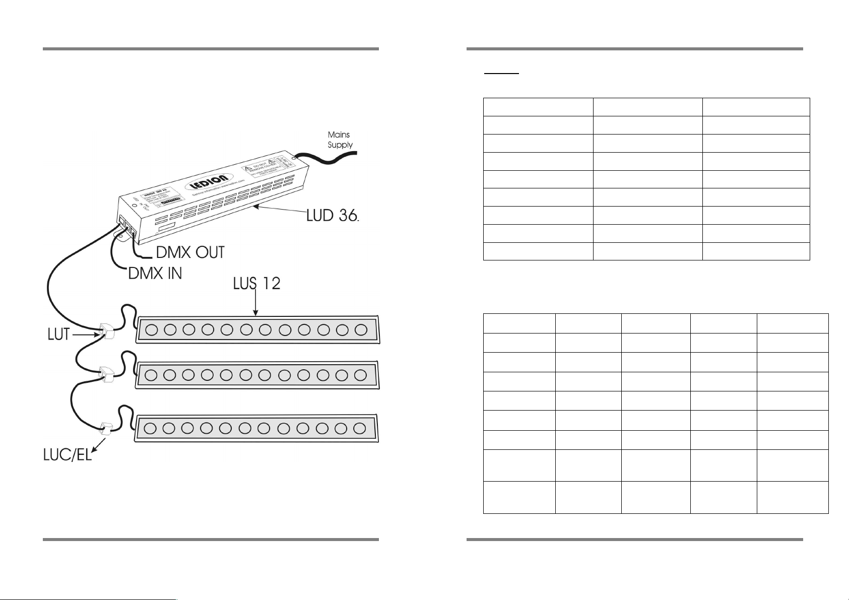
Congratulations on your purchase of the LUD 36 power supply. Your
new product offers many exciting features and can work in harmony
with all other products in the Ledion Ultra range to produce a versatile
architectural colour-changing tool. You can integrate the LUD 36 power
supply with an existing DMX system to give more sophisticated control
or use the built in colour changing features.(see pages 7-9.)This manual
contains important information to help you to achieve the best results
from this product. Please read through the manual before operating
the product.
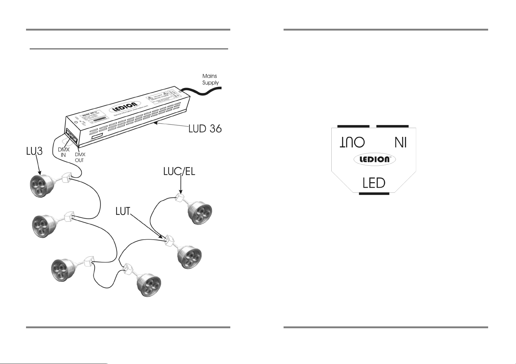
This power supply is designed for the Ledion Ultra LED products, and
will not operate LED units from any other manufacturers.
Instant features
•
If you are using the LUD 36 as the main controller for the lights,
go to pages 7-9
•
If you are integrating the LUD 36 with DMX512 as a system, go to
pages 5-6
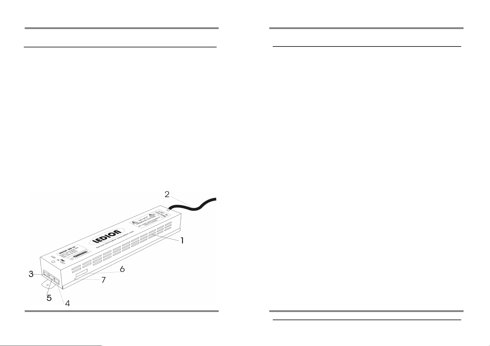
Specification
Power supply: AC 90V – 250V @ 60W
LED output: 36 LED Max Load 6 LED Min Load.
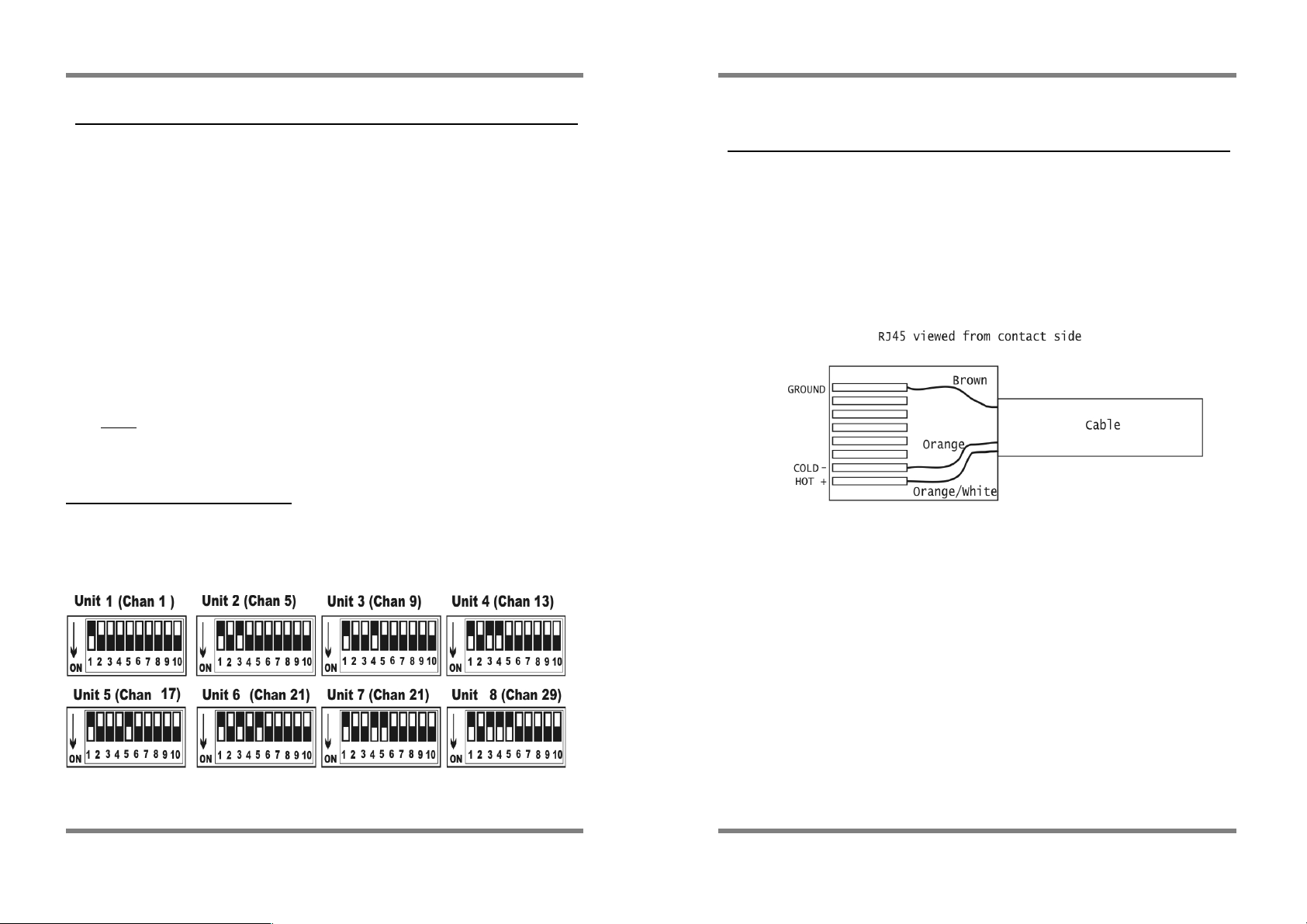
DMX input/thru: RJ45 Pin 1 Hot, Pin 2 Cold, Pin 8 Ground.
DMX Addressing
: 1 - 508
External Dimensions: Metric. 320mm x 63mm x 50mm.
Imperial. 12.6” x 2.5” x 2”
Weight: Metric 1 Kg. Imperial 2.2 lb
THIS POWER SUPPLY WILL ONLY RUN 36 LED’s.