Page 4
© 2021 ABB. All rights reserved.
Quick Start Guide
Connect Batteries (continued)
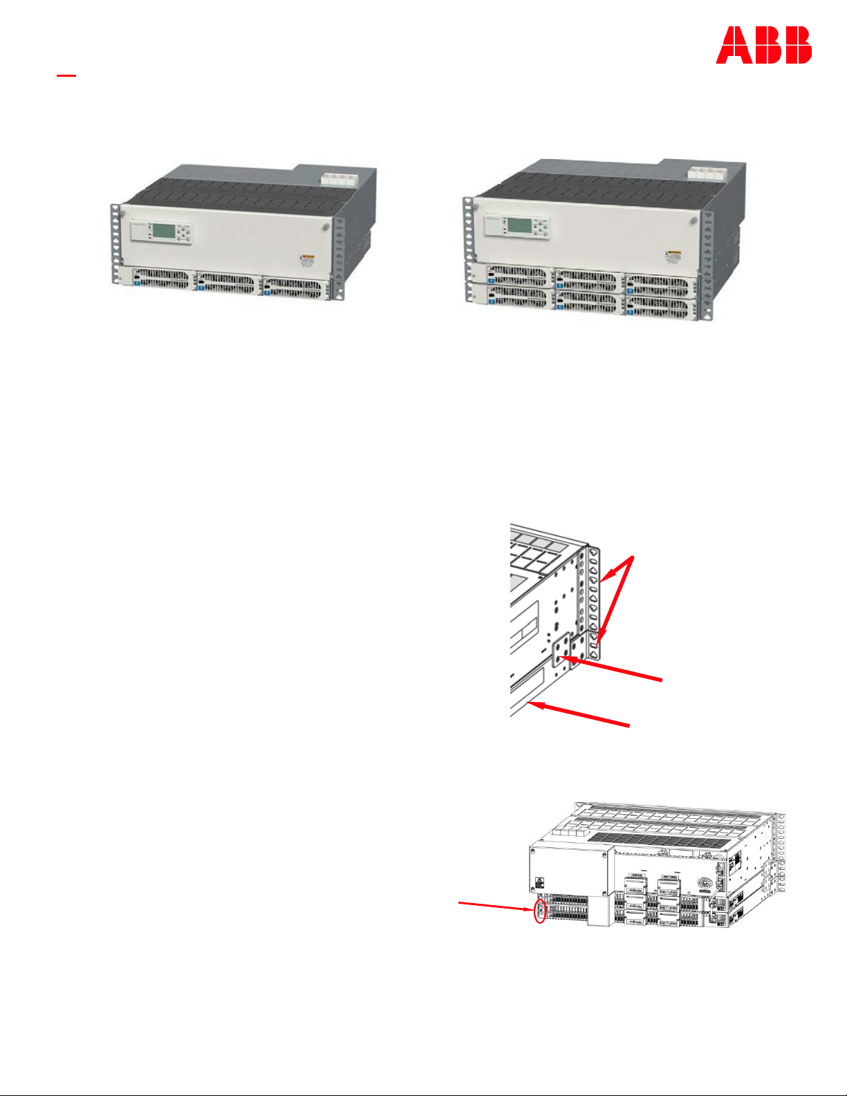
1. Connect Battery Return Cable to Return Bus. Battery Return Lug Landings - M8 bolts (lug not provided). Torque to 14 Nm
(120 in-lb) - 1/2” (13 mm) socket.
2. Verify that breaker is OFF (handle down).
CAUTION: Verify battery voltage and polarity with a voltmeter before proceeding.
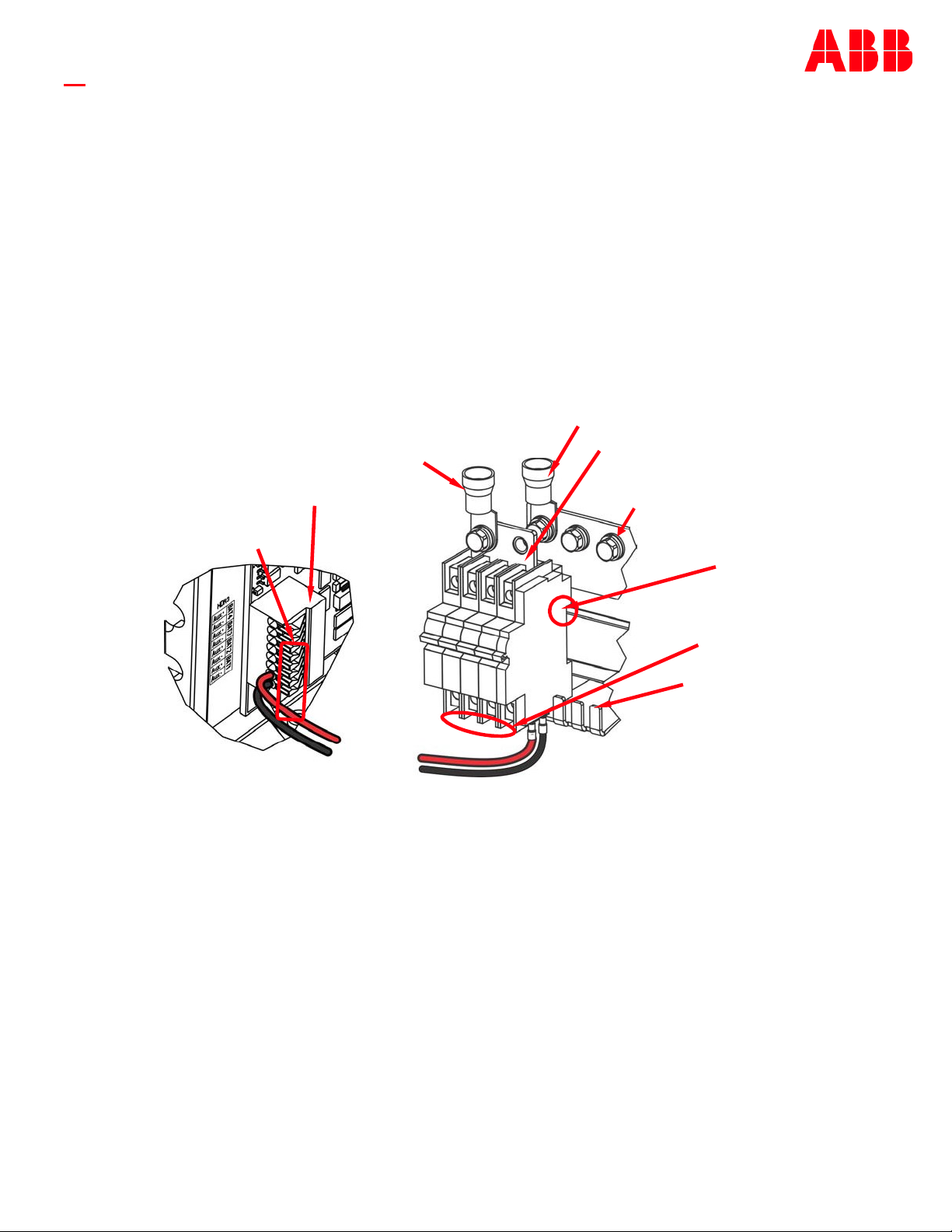
3. Connect Battery Cable to lug adapter (factory assembled to breaker). Battery Lug Landings - M8 bolts (lug not provided).
Torque to 14 Nm (120 in-lb) - 1/2” (13 mm) socket.
Note: Larger battery breaker may include adaptor bus for two connections.
4. Verify torque of adaptor and bus connection to circuit breaker. Torque to 2-2.3 Nm (20 in-lb) - #2 Phillips.
5. Repeat for additional Battery connections.
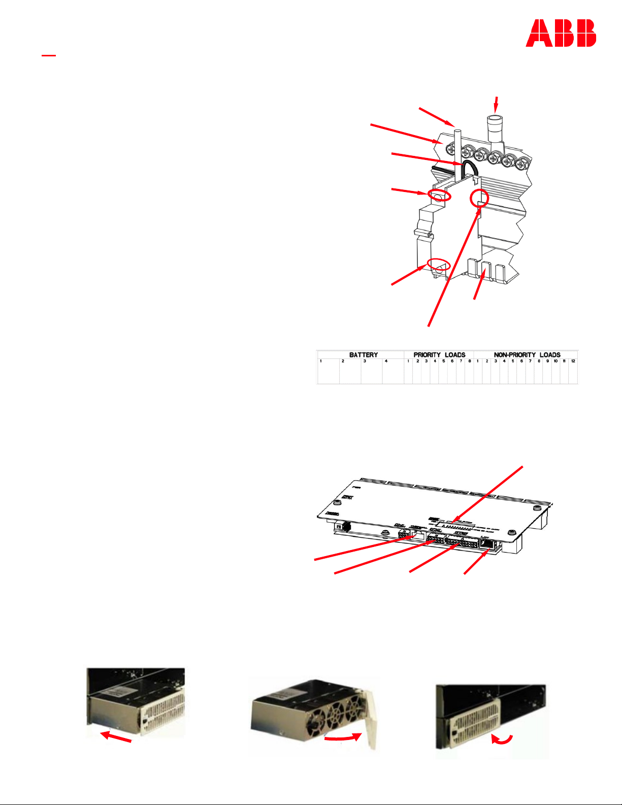
Step 6 - Connect Loads (Outputs)
For system with LVLD (two shelf system only), note positions of priority (critical) versus non-priority (non-critical)
loads. There can be up to 6 priority and 9 non-priority loads.
1. Verify that breaker is OFF (handle down).
2. Mount breaker to DIN rail.
a. Fully open the connection at breaker bottom - #2 Phillips.
b. Slide breaker over bus tab and fully engage top DIN rail.
IMPORTANT—Verify top DIN rail engagement.
a. Tighten the breaker bottom connection - #2 Phillips. Hold firmly downward and torque to 2-2.3 Nm (20 inlb).
3. Connect alarm wire to load breaker.
Note: This wire will be secured to the breaker along side the load wire.
a. Fully open the screw connection at breaker top - #2 Phillips.
b. Choose any wire from the bundle of black wires behind the breakers. Cut wire. Strip 10 mm (3/8”). Insert wire into
breaker load connection. Do not tighten the breaker connection.
Release Levers
Push to release
Lug Adapter
Alarm Card HDR3
Battery Connection
Battery Return Connection
DIN Rail Engagement
Return Bus
Bus Tabs
Breaker Bus
Connection
11 12
Alarm
Wires