Forgeon Bolt 650 User manual
Bolt
INSTRUCTIONS MANUAL
MANUAL DE INSTRUCCIONES

EN
Table of Contents
Introduction What’s in the box
Introduction.....................................................................................................
What’s in the box.............................................................................................
Safety and Protection......................................................................................
Bolt 650/ 750/ 850 Specications...................................................................
Installation.......................................................................................................
Important user information.............................................................................
02
02
03
04
07
00
Bolt is a modular 80+ GOLD certied power supply
tailored for those looking for efciency without
compromising on quality.
High quality Japanese capacitors, a 140mm fan with silent
PWM capability to keep all components well cooled and a
unique design.
Bolt comes with all standard protections (OVP, SPC, UVP,
OPP, OCP, OTP) for the safety and protection of the
components as well as different accessories for ease of
use and installation.
Included with your Forgeon Bolt 650/ 750/ 850 power
supply are the following ítems:
• Bolt Power Supply (1)
• Bolt QR Manual (1)
• Power Cord Cable (1)
• Installation Screws (4)
• Protection bag (1)
• Function test (1)
• 90° motherboard adapter (1)

EN
Safety and Protection
WARNING: This unit unit has no user-serviceable parts inside. Opening the casing
presents a risk of electrocution and will void the product’s warranty. Forgeon will not be
responsible for any result of improper use, including but not limited to, any use of the
product outside of its intended purpose or use inconsistent with the warranty terms
available online. (Warranty information is available at https://forgeon.es/garantia and this
manual is avaliable at https://forgeon.es/bolt/bolt_manual.pdf
Short-circuit protection (SCP)
Over current protection (OCP)
Over-voltage protection (OVP)
Over Power Protection (OPP)
Under Voltage Protection (UVP)
Over temperature protection (OTP)
Over-voltage protection for the 12V, 5V and 3.3V DC
outputs is required to comply with the ATX specication.
OVP shuts down the PSU in the event that the DC outputs
exceed a set level, determined by the PSU manufacturer.
The minimum voltage levels required for compliance are
13.4V for the +12V rail(s), 5.74V for the +5V rail and 3.76V
for the 3.3V rail.
The over-power protection (OPP) kicks in when the
power we pull from a PSU exceeds its maximum rated
capacity. Usually, the manufacturers give a little room for
overpowering the PSU, so the OPP threshold is set to 50 to
100W (in some cases even more) above the maximum rated
wattage of the PSU. In single +12V rail PSUs, where OCP
is meaningless in most cases, OPP takes over its role and
shuts down the PSU in case the +12V rail is overloaded.
A short-circuit is dened as any output impedance of less
than 0.1 ohms. Amongst other things, SCP ensures that the
PSU shuts down should the 3.3V, 5V and 12V rails short to
any other rail, or to ground. It also ensures that no damage
should occur to the unit, or your PC’s components in the
event of a short.
is an electronic overload protection circuit that is often
specied in data sheets as OCP (= Overcurrent Protection)
.The power supply as well as the connected loads are
electronically protected against overload by limiting the output
current to a maximum value. OCP is a feature that uses one or
more circuits to prevent a power supply from delivering more
current than its circuits and cables can handle.
Under-voltage protection for the 12V, 5V and 3.3V DC
outputs. UVP shuts down the PSU in the event that the
DC outputs exceed a set level, determined by the PSU
manufacturer.
Continuous high temperatures are undesirable and can
lead to malfunctioning or more damage to the supply,
connected circuits or downstream equipment. The over
temperature protection (OTP) therefore ensures that the
supply operates within the safe design temperature and
shuts the supply down whenever this is exceeded.

EN
MAIN-BOARD
CPU
PCI-E
x1
20+4Pin
4+4 CPU
SATA (2 cables)
Floppy adapter (4 pin)
MOLEX
x2
x3
x1
x8
600mm
700mm
550mm
SATA SATA SATA
6+2 PCIE
x3
550mm
IDE/SATA
550mm1 50mm
150mm
150mm1 50mm
150mm
SATA
IDE/SATA
550mm
MOLEX MOLEX MOLEX
150mm
FDD
AC INPUT AC100-240V 47-63HZ
DC OUTPUT +V5 +3.3V +12VMBPH +12VCPU +12VVGA1 +12VVGA2 -12V +5VSB
MAX OUTPUT 20A 20A 25A 25A 30A 30A 0.3A 2.5A
MAX
COMBINED
POWER
100W
300W 300W 360W 360W
650W
MAX POWER 650W
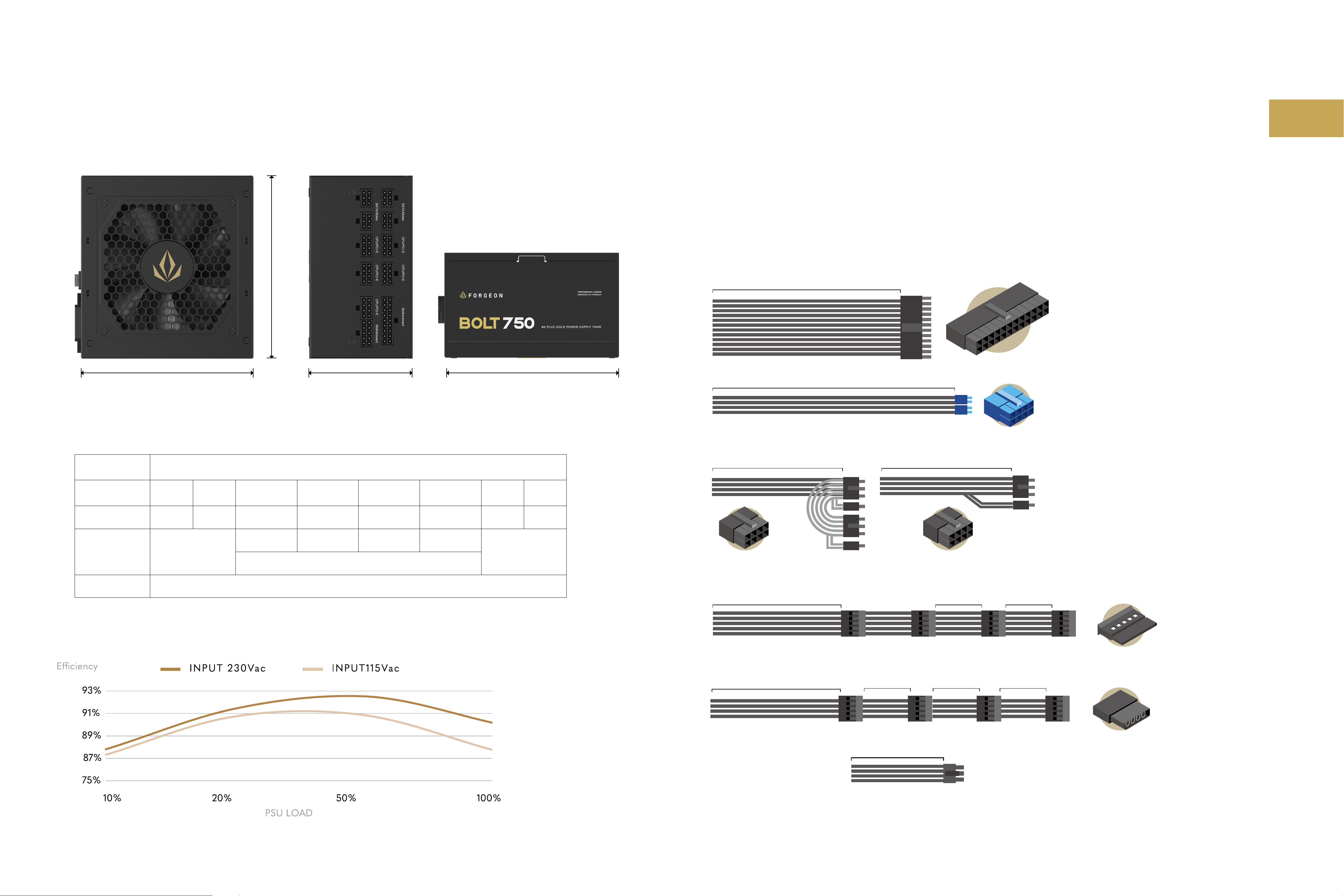
Cable Listing
Power table
Power efciency
Bolt 650W
160mm 160mm86mm
150mm

EN
AC INPUT AC100-240V 47-63HZ
DC OUTPUT +V5 +3.3V +12VMBPH +12VCPU +12VVGA1 +12VVGA2 -12V +5VSB
MAX OUTPUT 22A 22A 25A 25A 35A 35A 0.5A 2.5A
MAX
COMBINED
POWER
120W
300W 300W 420W 420W
750W
MAX POWER 750W
Cable Listing
Power table
Power efciency
Bolt 750W
MAIN-BOARD
CPU
PCI-E
x1
20+4Pin
4+4 CPU (2 cables)
SATA (2 cables)
Floppy adapter (
4 pin)
MOLEX
x2
x3
x1
x9
600mm
700mm
550mm
SATA SATA SATA
6+2 PCIE
x2
6+2 PCIE (2 cables)
x2
550mm
IDE/SATA
550mm 150mm
150mm
150mm 150mm
150mm
SATA
IDE/SATA
550mm 150mm
150mm
FDD
MOLEX MOLEX MOLEX SATA
160mm 160mm86mm
150mm

EN
AC INPUT AC100-240V 47-63HZ
DC OUTPUT +V5 +3.3V +12VMBPH +12VCPU +12VVGA1 +12VVGA2 -12V +5VSB
MAX OUTPUT 22A 22A 25A 25A 40A 40A 0.5A 2.5A
MAX
COMBINED
POWER
120W
300W 300W 480W 480W
850W
MAX POWER 850W
Cable Listing
Power table
Power efciency
Bolt 850W
MAIN-BOARD
CPU
PCI-E
x1
20+4Pin
4+4 CPU (2 cables)
SATA (2 cables)
Floppy adapter (
4 pin)
MOLEX
x2
x3
x1
x9
600mm
700mm
550mm
SATA SATA SATA
6+2 PCIE
x2
6+2 PCIE (2 cables)
x2
550mm
IDE/SATA
550mm 150mm
150mm
150mm 150mm
150mm
SATA
IDE/SATA
550mm 150mm
150mm
FDD
MOLEX MOLEX MOLEX SATA
160mm 160mm86mm
150mm
EN
Installation
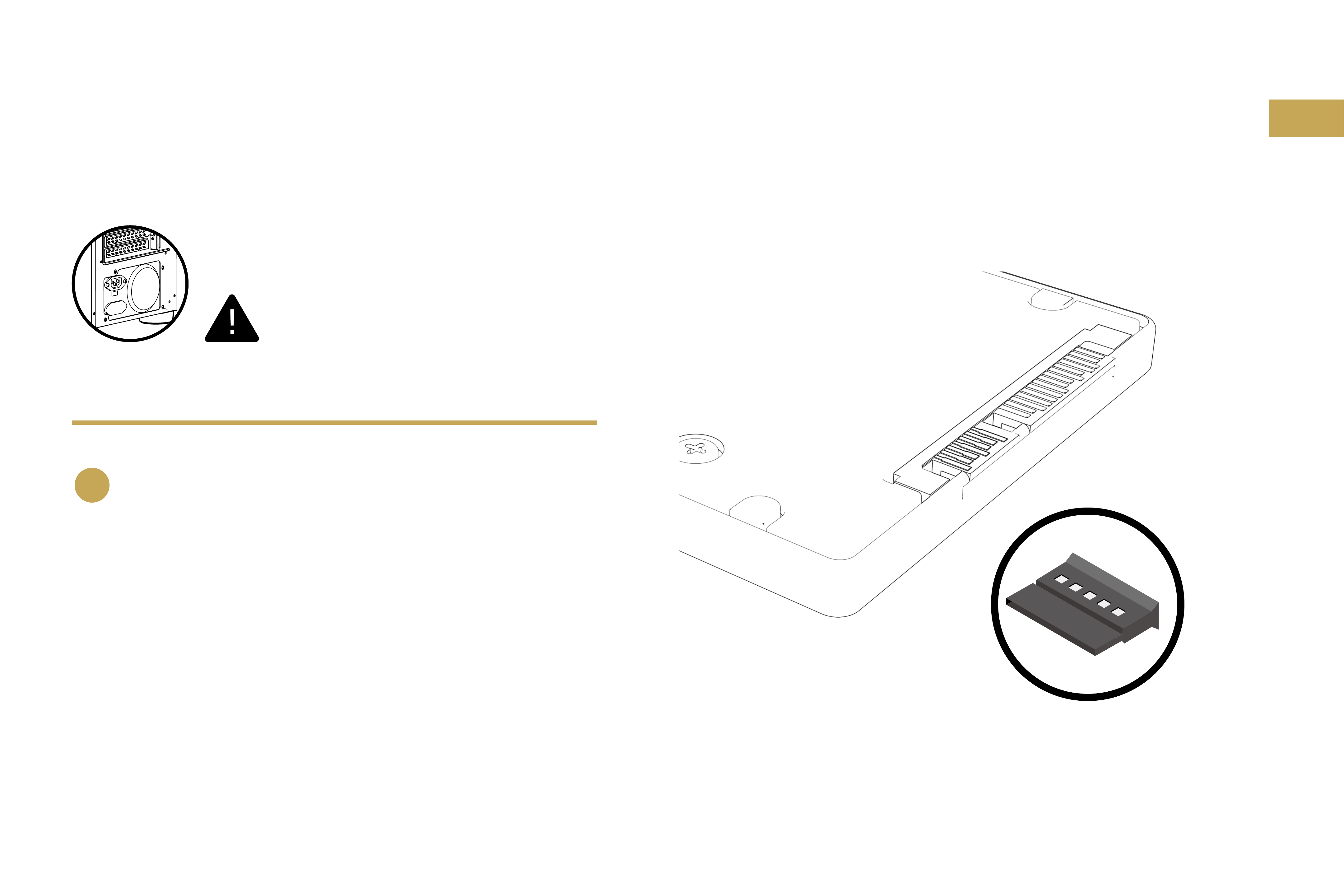
Removing your existing power supply If you are
building a new system, skip to Step B.
A
1. Disconnect the AC power cord from your wall outlet or UPS and
from the existing power supply.
2. Disconnect all the power cables from your video card, motherboard
and all other peripherals (SATA & MOLEX)
3. Follow the directions in your chassis manual and uninstall your
existing power supply.
4. Proceed to Step B.
SATA connector Reference
Disconnect the AC power
before installation

EN
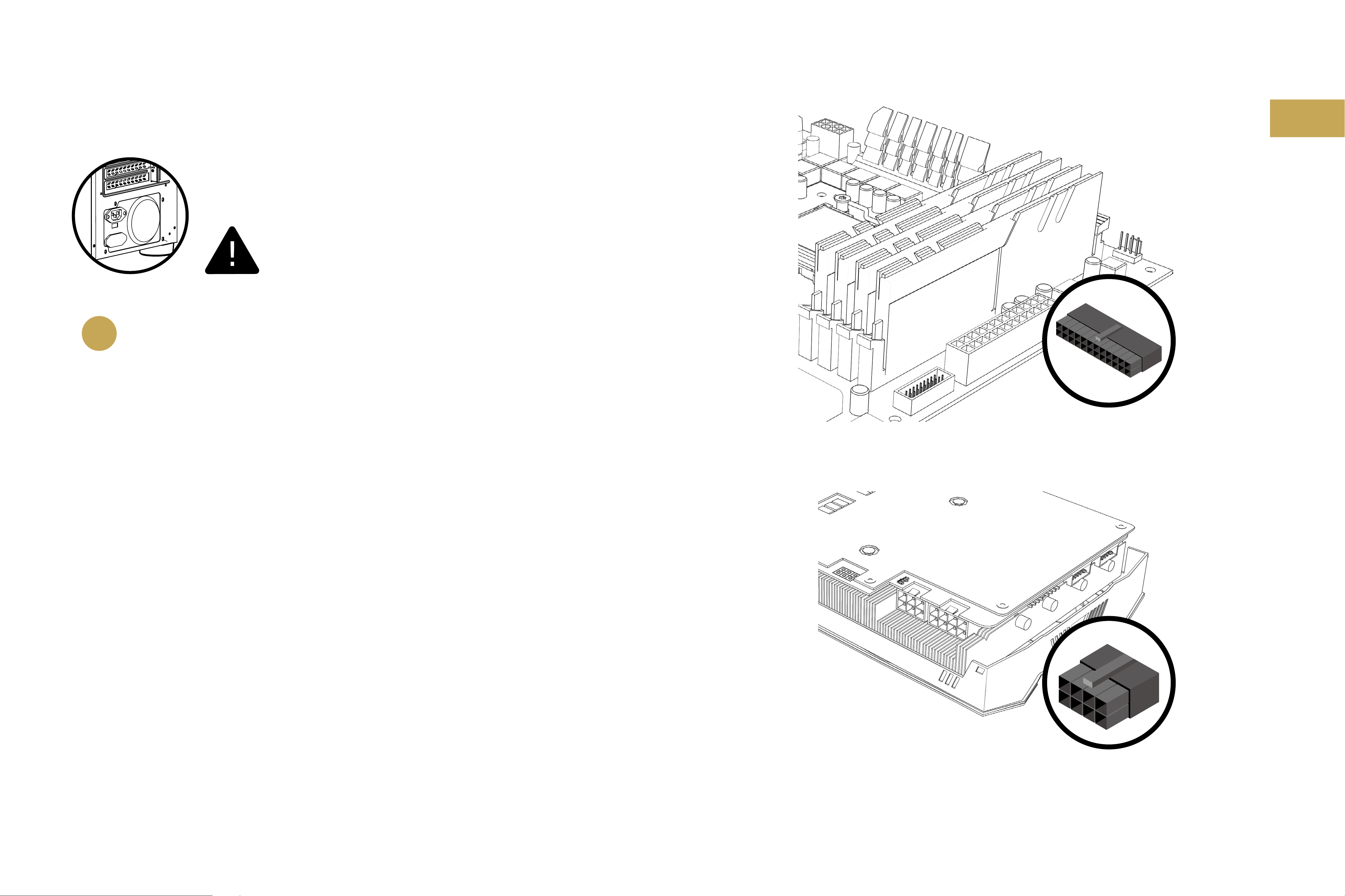
Installing Bolt power supply
B
1. Make sure the power supply’s AC power cable is not connected.
2. Follow the directions in your chassis manual and install the power supply with the screws
provided.
3. The main 24-pin power cable has a detachable 4-pin mechanism in order to support either a
24-pin or a 20-pin socket on the motherboard.
A.If your motherboard has a 24-pin socket, you may connect the 24-pin main power cable from
the power supply directly to your motherboard.
B. If your motherboard has a 20-pin socket, you must detach the four-pin cable from the 24-pin
connector, and then plug the 20-pin cable onto your motherboard without connecting the
four-pin connector.
4. Connect the eight-pin +12V (EPS12V) cable to the motherboard.
A.If your motherboard has an eight-pin +12V socket, connect the eight-pin cable directly to
your motherboard.
B. If your motherboard has a four-pin socket, detach the four-pin from the eight-pin cable, and
then plug this four-pin cable directly to your motherboard.
24-pin main power cable
Eight-pin +12V (EPS12V) cable
Disconnect the AC power
before installation

EN
Description and use of included accessories
1. Functional test "Tester" or power supply jumper:
This accessory allows you to turn on the power supply without having to connect it
to a motherboard, so you can check the proper functioning of it, or to check other
components such as cooling, fans etc..
2. 90° or "L" connector for the motherboard
This connector for the 24-pin motherboard cable is mainly used to facilitate cable
management and also to reduce the strain on the cables for better aesthetics and
longevity.
Additional Important user information
1. Install in accordance with all manufacturer instructions and safety warnings. Failure
to do so may result in damage to your power supply or system, and may cause
serious injury or death.
2. High voltages are present in the power supply. Do not open the power supply case
or attempt to repair the power supply; there are no user-serviceable components.
3. This product is designed for indoor use only.
4. Do not use the power supply near water, or in high temperature or high humidity
environments.
5. Do not install near any heat sources such as radiators, heat registers, stoves, or other
apparatus that produce heat.
6. Do not insert any objects into the open ventilation or fan grill area of the power
supply.
7. Do not modify the cables and/or connectors included with this power supply.
8. The 24-pin main power connector has a detachable 4-pin connector. This 4-pin
connector is not a P4 or ATX 12V connector. Do not force this cable in the P4 or
ATX +12V socket on the motherboard.
9. Failure to comply with any manufacturer instructions and/or any of these safety
instructions will immediately void all warranties and guarantees.

EN
Tabla de contenidos
Introducción Contenido de la caja
Introducción....................................................................................................
Contenido de la caja .......................................................................................
Seguridad y protección....................................................................................
Bolt 650/ 750/ 850 Características.................................................................
Instalación.......................................................................................................
Información importante de uso.......................................................................
10
10
11
12
15
18
Bolt una fuente de alimentación con certicación 80+
GOLD modular adaptada para quienes buscan eciencia
sin renunciar a la calidad.
Capacitadores japoneses de alta calidad, un ventilador
de 140mm con capacidad PWM silencioso para mantener
todos los componentes bien refrigerados y un diseño
único.
Bolt incluye con todas las protecciones estándar
(OVP, SPC, UVP, OPP, OCP, OTP) para la seguridad y
protección de los componentes además de diferentes
accesorios para facilitar su uso e instalación.
Forgeon Bolt 650/ 750/ 850 incluye los siguientes
elementos:
• Fuente de alimentación Bolt (1)
• Tarjeta manual QR Bolt (1)
• Cable de alimentación (1)
• Tornillos para instalación (4)
• Bolsa de protección (1)
• Test de funcionamiento (1)
• Adaptador de 90º para placa base (1)

EN
Seguridad y protección
ADVERTENCIA: Esta unidad no tiene partes reparables por el usuario en su interior. La apertura de la carcasa presenta un
riesgo de electrocución y anulará la garantía del producto. Forgeon no se hará responsable de un uso inadecuado, incluyendo,
pero sin limitarse a ello, cualquier uso del producto fuera de su nalidad o uso inconsistente con los términos de garantía
disponibles en línea. (La información sobre la garantía está disponible en https://forgeon.es/garantia y este manual está
disponible en https://forgeon.es/bolt/bolt_manual.pdf)
Protección contra cortocircuito (SCP)
Protección contra exceso de
corriente (OCP)
Protección contra sobrevoltaje (OVP)
Protección contra exceso de
energía (OPP)
Protección contra bajo-voltaje (UVP)
Protección contra exceso de
temperatura (OTP)
La protección contra sobretensiones para las salidas de 12V,
5V y 3.3V DC es necesaria para cumplir con la especicación
ATX. La OVP apaga la fuente de alimentación en caso de que las
salidas de CC excedan un nivel establecido, determinado por
el fabricante de la fuente de alimentación. Los niveles mínimos
de tensión requeridos para el cumplimiento son 13,4V para los
carriles de +12V, 5,74V para los carriles de +5V y 3,76V para los
carriles de 3,3V.
La protección contra el exceso de energía (OPP) se activa cuando
la energía que extraemos de una fuente de alimentación excede su
máxima capacidad nominal. Por lo general, los fabricantes dan un
poco de espacio para sobrealimentar la fuente de alimentación, por
lo que el umbral de OPP se establece en 50 a 100W (en algunos casos
incluso más) por encima de la potencia nominal máxima de la fuente
de alimentación. En las fuentes de alimentación de un solo carril de
+12V, donde el OCP no tiene sentido en la mayoría de los casos, el
OPP asume su papel y apaga la fuente de alimentación en caso de que
el carril de +12V se sobrecargue
Un cortocircuito se dene como cualquier impedancia de salida
de menos de 0,1 ohmios. Entre otras cosas, el SCP asegura que la
PSU se apaga si los rieles de 3,3V, 5V y 12V se cortocircuitan con
cualquier otro riel, o con la tierra. También asegura que no se
produzca ningún daño a la unidad, o a los componentes de su PC
en caso de un cortocircuito.
Es un circuito electrónico de protección contra la sobrecarga que a
menudo se especica en las hojas de datos como OCP (Overcurrent
Protection). La fuente de alimentación, así como las cargas
conectadas, están protegidas electrónicamente contra la sobrecarga
limitando la corriente de salida a un valor máximo. El OCP es una
función que utiliza uno o más circuitos para evitar que una fuente de
alimentación suministre más corriente de la que pueden soportar sus
circuitos y cables.
Protección de bajo voltaje para las salidas de 12V, 5V y 3.3V
DC. La UVP apaga la fuente de alimentación en caso de que las
salidas de CC excedan un nivel establecido, determinado por el
fabricante de la fuente.
Las altas temperaturas continuas no son deseables y pueden
provocar un mal funcionamiento o más daños en la alimentación,
en los circuitos conectados o en los equipos posteriores. Por ello,
la protección contra sobretemperatura (OTP) garantiza que el
suministro funcione dentro de la temperatura de diseño segura y lo
desconecta cuando se supera.

EN
MAIN-BOARD
CPU
PCI-E
x1
20+4Pin
4+4 CPU
SATA (2 cables)
Floppy adapter (4 pin)
MOLEX
x2
x3
x1
x8
600mm
700mm
550mm
SATA SATA SATA
6+2 PCIE
x3
550mm
IDE/SATA
550mm1 50mm
150mm
150mm1 50mm
150mm
SATA
IDE/SATA
550mm
MOLEX MOLEX MOLEX
150mm
FDD
Potencia
nominal (AC) AC100-240V 47-63HZ
Corriente de
salida (DC) +V5 +3.3V +12VMBPH +12VCPU +12VVGA1 +12VVGA2 -12V +5VSB
Carga máxima 20A 20A 25A 25A 30A 30A 0.3A 2.5A
Carga máxima
combinada 100W
300W 300W 360W 360W
650W
Potencia Total 650W
Litado de cables y conexiones
Tabla de alimentación
Eciencia de la fuente de alimentación
Bolt 650W
160mm 160mm86mm
150mm
EN
160mm 160mm86mm
150mm
Potencia
nominal (AC) AC100-240V 47-63HZ
Corriente de
salida (DC) +V5 +3.3V +12VMBPH +12VCPU +12VVGA1 +12VVGA2 -12V +5VSB
Carga máxima 22A 22A 25A 25A 35A 35A 0.5A 2.5A
Carga máxima
combinada 120W
300W 300W 420W 420W
750W
Potencia Total 750W
Listado de cables y conexiones
Tabla de alimentación
Eciencia de la fuente de alimentación
Bolt 750W
MAIN-BOARD
CPU
PCI-E
x1
20+4Pin
4+4 CPU (2 cables)
SATA (2 cables)
Floppy adapter (
4 pin)
MOLEX
x2
x3
x1
x9
600mm
700mm
550mm
SATA SATA SATA
6+2 PCIE
x2
6+2 PCIE (2 cables)
x2
550mm
IDE/SATA
550mm 150mm
150mm
150mm 150mm
150mm
SATA
IDE/SATA
550mm 150mm
150mm
FDD
MOLEX MOLEX MOLEX SATA

EN
160mm 160mm86mm
150mm
Potencia
nominal (AC) AC100-240V 47-63HZ
Corriente de
salida (DC) +V5 +3.3V +12VMBPH +12VCPU +12VVGA1 +12VVGA2 -12V +5VSB
Carga máxima 22A 22A 25A 25A 40A 40A 0.5A 2.5A
Carga máxima
combinada 120W
300W 300W 480W 480W
850W
Potencia Total 850W
Listado de cables y conexiones
Tabla de alimentación
Eciencia de la fuente de alimentación
Bolt 850W
MAIN-BOARD
CPU
PCI-E
x1
20+4Pin
4+4 CPU (2 cables)
SATA (2 cables)
Floppy adapter (
4 pin)
MOLEX
x2
x3
x1
x9
600mm
700mm
550mm
SATA SATA SATA
6+2 PCIE
x2
6+2 PCIE (2 cables)
x2
550mm
IDE/SATA
550mm 150mm
150mm
150mm 150mm
150mm
SATA
IDE/SATA
550mm 150mm
150mm
FDD
MOLEX MOLEX MOLEX SATA

EN
Instalación
Quitar la fuente de alimentación existente.
Si está montando un nuevo sistema,
proceda al Paso B.
A
1. Desconecte el cable de alimentación de CA de su toma de corriente
y de la fuente de alimentación existente.
2. Desconecte todos los cables de alimentación de su tarjeta de vídeo,
placa base y todos los demás periféricos (SATA y MOLEX)
3. Siga las instrucciones del manual del chasis y desinstale la fuente de
alimentación existente.
4. Proceda al paso B. SATA connector Reference
Disconnect the AC power
before installation
EN
Instalación de la fuente de alimentación Bolt
B
1. Asegúrese de que el cable de alimentación de CA de la fuente de alimentación no esté
conectado.
2. Siga las instrucciones del manual del chasis e instale la fuente de alimentación con los tornillos
suministrados.
3. El cable de alimentación principal de 24 clavijas tiene un mecanismo desmontable de 4 clavijas
para soportar una toma de 24 clavijas o de 20 clavijas en la placa base.
A.Si su placa base tiene un enchufe de 24 pines, puede conectar el cable de alimentación
principal de 24 pines de la fuente de alimentación directamente a su placa base.
B. Si la placa base tiene una toma de 20 clavijas, debe separar el cable de cuatro clavijas del
conector de 24 clavijas y luego conectar el cable de 20 clavijas a la placa base sin conectar
el conector de cuatro clavijas.
4. Conecte el cable de ocho clavijas +12V (EPS12V) a la placa base.
A.Si su placa base tiene un conector de ocho pines +12V, conecte el cable de ocho pines
directamente a su placa madre.
B. Si su placa base tiene un enchufe de cuatro clavijas, separe las cuatro clavijas del cable de
ocho clavijas y luego conecte este cable de cuatro clavijas directamente a su placa madre.
24-pin main power cable
Eight-pin +12V (EPS12V) cable
Disconnect the AC power
before installation

EN
Descripción y uso de los accesorios incluidos
1. Test de funcionamiento “Tester” o puente de alimentación:
Este accesorio permite encender la fuente de alimentación sin necesidad de
conectarla previamente a una placa base, por lo que se puede así comprobar el
buen funcionamiento de la misma, o para comprobar otros componentes como por
ejemplo una refrigeración, ventiladores etc.
2. Conector 90ºo en “L” para la placa base Este conector para el cable de 24 pin de
la placa base se usa principalmente para facilitar la gestión del cableado y además
reducir la tensión de los mismos proporcionando una mejor estética y longevidad.
Adicional Información importante de uso
1. Instálela de acuerdo con las instrucciones del fabricante y las advertencias de
seguridad. El no hacerlo así puede provocar daños en la fuente de alimentación o en
su sistema y eventuales lesiones graves o incluso la muerte.
2. En la fuente de alimentación están presentes altos voltajes. No abra la carcasa de la
fuente de alimentación ni intente reparar la fuente de alimentación, pues carece de
componentes que pueda reparar el usuario.
3. Este producto está diseñado únicamente para uso en interiores.
4. No utilice la fuente de alimentación cerca de agua, con altas temperaturas ni en
entornos con niveles de humedad altos.
5. No la instale cerca de fuentes de calor como radiadores, convectores, estufas u
otros aparatos que produzcan calor.
6. No introduzca objetos en la abertura de ventilación o en la zona de la rejilla del
ventilador de la fuente de alimentación.
7. No modique los cables o conectores incluidos con esta fuente de alimentación.
8. El conector de alimentación principal de 24 pines tiene un conector desmontable
de cuatro pines. Este conector de 4 pines no es un conector P4 o ATX de 12 V. No
introduzca a la fuerza este cable en el socket P4 o ATX +12 V de la placa base.
9. El incumplimiento de las instrucciones de seguridad del fabricante o cualquiera
de estas instrucciones de seguridad dejarán inmediatamente sin efecto cualquier
garantía.
Bolt
This manual suits for next models
2
Table of contents
Languages:


