Ledvance PHASE EV User manual

Page 1of 22
LEDVANCE PHASE EV
Installation Guide
Level 2 Commercial Charging Station
Perfect for facility managers of office, multi-residential,
retail, education, hospitality, and other business
locations. LEDVANCE PHASE EV Level 2 Commercial
Charging Station is offered in wall mounted units or a
free-standing pedestal where two units can be
mounted side-by-side or back-to-back. With powerful
software integration from AmpUp, LEDVANCE PHASE
EV combines performance and value to deliver fast
charging at an affordable price.
WARNING
−WARNING: TO AVOID FIRE, SHOCK OR DEATH, TURN OFF POWER at the circuit breaker or fuse and test
that the power is off before wiring! Do not remove circuit protective devices or any other component until power
is turned off.
−WARNING: TO AVOID FIRE, SHOCK OR DEATH, carefully read the charging instructions in your vehicle’s
manual before charging and heed the following warnings:
−DO NOT put your fingers into the vehicle connector.
−DO NOT use this product if the flexible power cord is frayed, has broken insulation or any other signs of damage.
−DO NOT use this product if the enclosure or the EV connector is broken, cracked, open, or shows any other
indication of damage.
−WHEN USING THIS DEVICE AROUND CHILDREN, supervise closely.
−TO REDUCE THE RISK OF FIRE, CONNECT ONLY TO A CIRCUIT PROVIDED WITH BELOW AMPERES
maximum branch circuit over-current protection in accordance with the National Electrical Code NFPA 70®, and
the Canadian Electrical Code, Part I, C22.1.
Models
Circuit Breaker Rating
EVC48ALVL2C1, EVC48ALVL2C1WH,
EVC48ALVL2C1GY
60A
−DO NOT operate charger in temperatures outside its operating range of -22°F to 122°F (-30°C to 50°C)
Please Read All Instructions Before Attempting Installation

Page 2of 22
Contents
INTRODUCTION
Safety Precautions
3
Compliance
3
What’s Included
4
Tools You Will Need
4
Specifications
5
Unit Parts
6
INSTALLATION
Get Started
7
Installing the Mounting Plate
8
Preparing the Charger
9
Mounting the Charger
10
Electrical Wiring
11
Current Adjustment
11
Closing the Charger
12
Installing the Holster and Cable Hanger
13
How to Setup WiFi Connection
14
OPERATION
Status Light Bar
16
Charger Screens
16
Charging
19
Troubleshooting
19
Warranty
21

Page 3of 22
Safety Precautions
IMPORTANT:
READ CAREFULLY BEFORE INSTALLING THE CHARGER. RETAIN FOR FUTURE REFERENCE.
GENERAL:
Upon receipt of the charger, thoroughly inspect for any freight damage which should be brought to the
attention of the delivery carrier.
Compliance
FCC Statement:
This equipment has been tested and found to comply with the limits for a Class B digital device, pursuant
to part 15 of the FCC Rules. These limits are designed to provide reasonable protection against harmful
interference in a residential installation. This equipment generates uses and can radiate radio frequency
energy and, if not installed and used in accordance with the instructions, may cause harmful interference
to radio communications. However, there is no guarantee that interference will not occur in a particular
installation. If this equipment does cause harmful interference to radio or television reception, which can
be determined by turning the equipment off and on, the user is encouraged to try to correct the
interference by one or more of the following measures:
•Reorient or relocate the receiving antenna.
•Increase the separation between the equipment and receiver.
•Connect the equipment into an outlet on a circuit different from that to which the receiver is
connected.
•Consult the dealer or an experienced radio/TV technician for help.
Industry Canada (IC) Statement:
This device complies with Industry Canada licence-exempt RSS standard(s). Operation is subject to the
following two conditions: (1) this device may not cause harmful interference, and (2) this device must
accept any interference received, including interference that may cause undesired operation.
Le présent appareil est conforme aux CNR d'Industrie Canada applicables aux appareils radio exempts
de licence. L'exploitation est autorisée aux deux conditions suivantes : (1) l'appareil ne doit pas produire
de brouillage, et (2) l'utilisateur de l'appareil doit accepter tout brouillage radioélectrique subi, même si le
brouillage est susceptible d'en compromettre le fonctionnement.

Page 4of 22
MPE (Maximum Permissible Exposure) Requirements
To satisfy FCC / IC RF exposure requirements, a separation distance of 20 cm or more should be
maintained between the antenna of this device and persons during device operation.
To ensure compliance, operations at closer than this distance is not recommended.
Les antennes installées doivent être situées de façon à ce que la population ne puisse y être exposée à
une distance de moins de 20 cm. Installer les antennes de façon à ce que le personnel ne puisse
approcher à 20 cm ou moins de la position centrale de l’ antenne.
La FCC des États-Unis stipule que cet appareil doit être en tout temps éloigné d’au moins 20 cm des
personnes pendant son fonctionnement.
Changes or modifications not expressly approved by the party responsible for compliance could void the
user's authority to operate the equipment.
What’s Included
- 1 x charger
- 1 x cable hanger
- 1 x charge coupler holster
- 1 x M25 cable strain relief (cable gland)
- 1 x M32 cable strain relief (cable gland)
- 8 x M5 wall anchors w/screws (for holster & hanger)
- 3 x M6 wall anchors w/screws (for charger wall mount)
- 1 x T20 25mm tamper-proof Torx® bit, 1/4in hex
Tools You Will Need
- 1/4 in hex bit driver
- Phillips screwdriver (#2)
- Wire cutter & stripper
- Crimping pliers
- Drill or hammer drill

Page 5of 22
Specifications
FEATURES AND FUNCTIONS
Charging mode
Level 2
Vehicle connection
SAE J1772 (Type 1 connector)
Cable length
25ft
Display
4.3in LCD w/charging status light bar
COMMUNICATION
Interfaces
4G, WiFi, Ethernet
SIM card
Super SIM card (shipped installed)
User authentication
RFID, QR Code, App
Back-end protocol
OCPP 1.6, upgradeable to OCPP 2.0.1
Software upgrade
Over-the-air (OTA)
Software provider
AmpUp
ELECTRICAL DESIGN
Power supply voltage
AC level 2, 208/240V
Rated frequency
60Hz
Rated current
Up to 48A –16/32/40/48 amp selectable
Power output
Max 11.5kW
Input connection
Hardwired –terminal lug screws
Primary wire gauge
8AWG
Power requirements
208V (single phase), 240V (single or split phase)
Metering
Revenue grade embedded metering ± 1% accuracy
Ground fault protection
Standard
Over voltage protection
Standard –6kV surge suppression
Over current protection
Standard
GENERAL DESIGN
Environmental rating
NEMA 4 enclosure (UL50E), IK08 impact protection
Ingress protection
IP66
Dimensions (H x W x D)
16.34” x 9.45” x 5.59” (415mm x 240mm x 117mm)
Weight
19.8-22 lbs. (9-10kg)
Operating temp
-22°F to 122°F (-30°C to 50°C)
Storage temp
-40°F to 167°F (-40°C to 75°C)
Cooling
Natural cooling –fanless
Paint
UV protection
CERTIFICATIONS AND STANDARDS
Standards
ETL (UL2594, UL2231, UL1998, UL991)
EMC
FCC Part 15 Class B
ENERGY STAR (EVSE v1.1)
Yes
California Type Evaluation Program (CTEP)
In progress
Warranty
5-Year warranty

Page 6of 22
Unit Parts
1. Fuse
2. Debug serial port
3. Download interface
4. 485 interface
5. CAN interface
6. USB interface
7. Coin cell battery
8. Dip switch control
9. TF card holder
10. Ethernet interface (RJ45)
11. PF pulse interface
12. SIM card interface
13. Power switch
14. Input L1
15. Input L2
16. Input Ground
17. Cable Ground
18. Reserved interface
19. CP interface
20. RS485 interface A
21. RS485 interface B
22. Cable L2
23. Cable L1

Page 7of 22
Get Started
Step 1: Subscribe to a Software Charging Plan
The site host, property manager, or the owner must go to https://payments.ampup.io to subscribe to a
software charging plan. A software charging plan is required to access the Community Manager portal
where you will be able to customize various features that are included with your plan. We recommend
completing this step before or on installation day, prior to activation for a smooth progression. You will
receive login credentials via email for AmpUp Community Manager (https://community.ampup.io/login)
after the charger is installed and activated.
Step 2: Site & Charger Registration
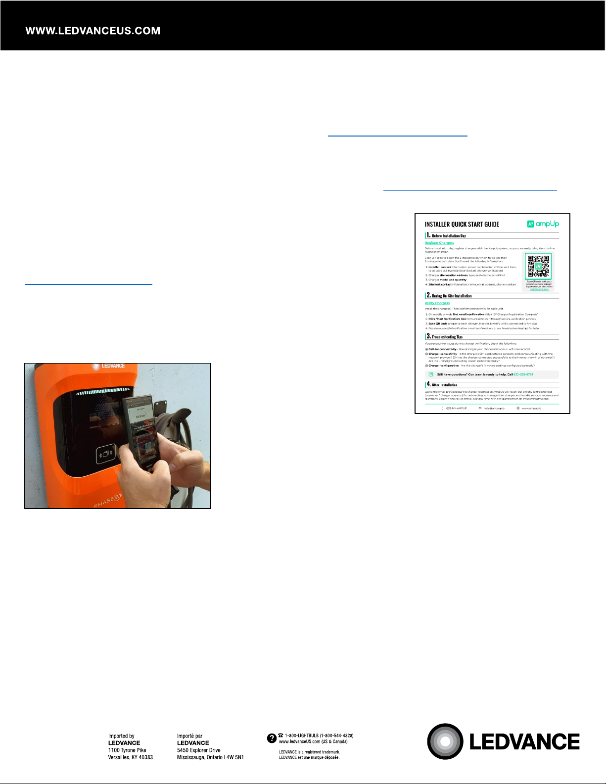
Before or on installation day, register chargers with the AmpUp system,
so you can easily bring them online during installation. Scan the QR
code on the Installer Quick Start Guide or go to
https://register.ampup.io.
Step 3: Install the Charger
Follow the steps below to install and power up your charger(s). Then
confirm connectivity for each unit.
Step 4: Activate the Charger
This charger has a pre-installed super SIM card that will
automatically detect and connect to the nearest cellular network
once it is connected to power. On mobile or web, simply open the
registration email that you received from AmpUp titled “EV Charger
Registration Complete” and tap on “Start Verification”. Scan the
“Scan to Charge” QR code on the charger to complete the verification process. Call AmpUp at 833-692-
6787 to confirm activation.
AmpUp will reach out to the site-host (customer / charger operator) for onboarding to manage their
charger and handle support requests and questions within the next 30 minutes to an hour. You will also
get login credentials for the AmpUp Community Manager.
Your charger(s) can be installed and operational within the same day if you follow the steps above. The
site-host must subscribe to a charging plan before or on installation day.
Still have questions? The AmpUp team is ready to help. Call 833-692-6787.

Page 8of 22
Installing the Mounting Plate
1. Remove the 2 screws –one on each side of the charger to detach the wall mounting plate from the
charger.
2. Place the wall mounting plate against the wall as a template as shown in the diagram below and mark
the 3 mounting holes. (Suggested height from the ground to the bottom holes is approximately 45.28
inches.)
3. Drill the 3 holes with an appropriate sized bit and secure the wall mounting plate using the included
M6 wall anchors and screws.
If installing with a pedestal, please
see separate Pedestal
Installation Instructions.
MIN
MAX

Page 9of 22
Preparing the Charger
1. Remove the cover frame from the front of the charger by unscrewing the 2 screws on top and 1 screw
from the bottom of the charger.
2. Once the 3 screws are removed, carefully lift the cover outward and up to detach the cover frame.
3. Remove the 6 screws to take off the access panel cover.
For Rear Wiring
Remove the rear plug(s) by loosening the hex nut in a counterclockwise direction. Then use the same plug to
cover the hole at the bottom of the charger. Use the included cable strain relief to run the wiring to the charger.
For Bottom Wiring
Use the included cable strain relief to run your wiring up from the bottom of the charger.

Page 10 of 22
Mounting the Charger
1. Align the charger to the wall mounting plate and hang it as shown in the illustration below.
2. Secure the charger to the wall mounting plate with the 2 original screws.
For rear wiring installation, use the
included cable strain relief and feed the
power supply wires through the rear port
with enough length to connect the wires to
the terminals.
Strain relief must be installed for IP
rating.

Page 11 of 22
Electrical Wiring
1. For bottom wiring installation, use the included cable strain relief and feed the power supply wires
through the bottom port with enough length to easily connect the wires to the terminals.
2. Connect the electrical wires L1, L2, and Ground to the appropriate terminals. See diagram below or
refer to the Unit Parts.
Current Adjustment
The default current setting is 48A but this charger can be adjusted down to 40A, 32A, or 16A using the dip
switches. See illustration below.

Page 12 of 22
Closing the Charger
1. Before closing the charger, check to make sure that all power supply wires are connected to the
appropriate terminals.
2. If you plan to use an Ethernet cable (LAN cable) for your network, make sure that it is properly seated
in the RJ45 port.
3. Check the pre-installed super SIM card to make sure it is properly seated in the SIM card slot.
4. Confirm the dip switches position for the desired Amperage.
5. Make sure the power switch is in the ON position.
6. Reinstall the wiring cover as shown below with the original 6 screws.
7. Reinstall the cover frame with the original 3 screws.

Page 13 of 22
Installing the Holster and Cable Hanger
You may place the holster and cable hanger wherever it is most convenient, being sure that the location
does not place any tension on the charging cable.
1. Place the holster against the wall and mark the mounting holes.
2. Drill the 4 holes with an appropriate sized bit and secure the holster with the included M5 wall
anchors and screws. (Suggested height from the ground is 33.5 inches)
3. Repeat the process for the cable hanger.
Cable Hanger
Suggested Mounting

Page 14 of 22
How to setup WiFi Connection
If you need to use WiFi instead of the cellular connection, please follow the steps below:
1. Power on the charger.
2. Use a smart phone, tablet, or laptop and open the WiFi settings. You will see a network name
starting with “LHxxxxxxx-xxx75342”(see example below). The last 5 digits of the network should
match the last 5 digits of your charger Serial Number. Select the network to establish a connection
from your device to the charger.
3. Open a web browser (Google Chrome or Microsoft Edge if using a laptop) and key in “192.168.4.1”
into the URL address field. Press <enter> and it will take you to the EVSE CONFIGURATION
page.
4. Fill in the default password “12345” to access the EVSE CONFIGUATION tool. We recommend
that you change this password under the Advanced Options to prevent unauthorized access in
the future.
Note: As a security measure, you have approximately 3 minutes from the time the charger is
powered up to connect via this method to access the EVSE CONFIGURATION. If session has
expired, cycle power to the charger and repeat.

Page 15 of 22
5. Under User Options, enter your WiFi SSID and Password that you would like to use.
6. Click <SAVE> and wait for the popup confirmation. Then click <RESET> to restart the charging
station with the new settings. Once the new settings have been uploaded, the charger light bar will
blink green a few times.
Enter your network WiFI SSID and
Password here.
Aside from the WiFi SSID, WiFi Password, and New
password fields, DO NOT make changes to the other
fields.

Page 16 of 22
Status Light Bar
Charger Screens
Power On Standby / Ready to Charge

Page 17 of 22
Preparing –Not connected to a vehicle Preparing –Connected to a vehicle
Charging Settlement / End of Session
Abnormal Status Fault

Page 18 of 22
Out of Service Update Status
Update Successful Update Failed
Vehicle is not ready to receive charge System Fault Settlement / End of Session

Page 19 of 22
Charging
There are multiple ways to start a charging session:
- Scan “Scan to Charge” QR code with your smart mobile device.
- Scan the appropriate (iOS or Android) QR code to download the AmpUp App for your smart mobile
device. Then use the AmpUp App to start charging.
- Scan RFID card (card must be connected to your AmpUp account or registered in the Community
Manager)
- Call AmpUp Customer Service 833-692-6787.
- Site-host can manually remote-start a charging session.
Troubleshooting
Note that some errors will initiate an automatic reset after 15 seconds if the detected fault is resolved. In
addition, the site host can use the Community Manager to initiate soft reset and hard reset.
Disconnecting the charge coupler from the vehicle will clear the display screen and return it to the
Standby Screen.
If the error does not automatically reset, make sure that the charge coupler is not connected to a vehicle.
Then power cycle the unit by switching the circuit breaker off and on.
If the error persists, contact AmpUp Customer Service at 833-692-6787.
For more information about LEDVANCE PHASE EV™, visit https://phaseev.ledvance.com/

Page 20 of 22
Fault Code
Solution
11 –CP voltage anomaly
Check the connection of charging connector and EV inlet.
Disconnect and reconnect the charging connector.
13 –Undervoltage input
Measure the input voltage to see if it is abnormal.
14 –Overvoltage input
Measure the input voltage to see if it is abnormal.
15 –Over temperature
protection
Turn off the charger power to cool down the machine before powering
it on again. Make sure that the charger is not covered or installed in
a high temperature environment. If the situation recurs, please power
off and stop using the machine immediately, then contact Customer
Service.
16 –Metering fault
Power off and restart the device. Turn circuit breaker off and then on.
17 –Leakage protection
Check whether the charging connector, charging cable, and EV inlet
are damaged or wet. Power off, disconnect and reconnect the
charging connector and restart.
18 –Output shortage
Check whether the charging connector and its cable are damaged or
wet.
19 –Output over current
Check whether the charging connector is correctly inserted to the EV
inlet. Check whether the OBC is normal. Check the maximum
current settings of the charger.
21 –EV response timeout
Battery of EV is full. Check if the charging connector is properly
inserted to the EV inlet. Disconnect and reconnect the charging
connector.
22 –EV not supported
This EV does not meet the SAE J1772 and cannot be charged.
23 –Relay sticking
The device is damaged and needs to be returned to the manufacturer
for repair. Contact Customer Service.
24 –CCID sensor fault
The sensor is damaged and needs to be returned to the manufacturer
for repair. Contact Customer Service.
25 –Ground fault
Charger is not grounded; check input power and all connections.
Table of contents
Other Ledvance Batteries Charger manuals