LEGRAND Evolution ATCFF User manual

1
Wiremold l ctrical syst ms conform to and should b prop rly
ground d in complianc with r quir m nts of th curr nt National
El ctrical Cod or cod s administ r d by local authoriti s.
All l ctrical products may pr s nt a possibl shock or fir
hazard if improp rly install d or us d. Wir mold l ctrical products may
b ar th mark as UL List d and/or Classifi d and should
b install d in conformanc with curr nt local and/or th National
El ctrical Cod .
Products Covered: 6ATCFF, 6STC, 6CFFTC, 15FFHA, 152CHA, CE6ATCFF
CAUTION DO NOT operate tile stripper, cleaning, or resur acing equipment over top o covers. This may result in
damage to the sur ace inish o the product.
Suitable or use in air handling spaces in accordance with Sec. 300-22 (C) o the National Electrical Code.
Evolution™Series
6" Furniture Feed Poke-Thru Devices
I N S T A L L A T I O N I N S T R U C T I O N S
Installation Instruction No.: 1 007 155 R2 – Updated May 2010
24" [610mm] Min
Center – Center
7 1/4"
[166mm]
CAUTION: Be certain to locate hole at least 6" [152mm] rom any wall or
pillar to leave enough room or Poke-Thru cover assembly.
IMPORTANT: Please read all instructions
be ore beginning.
CAUTION: Minimum spacing o 2 t on center and not more than
one device per each 65 square eet o loor area in
each span.
Step 2 R mov 7 1/4" dia. [166mm] s ction from
carp t or til . Us t mplat provid d.
Step 1 Layout and locat position of hol (s).
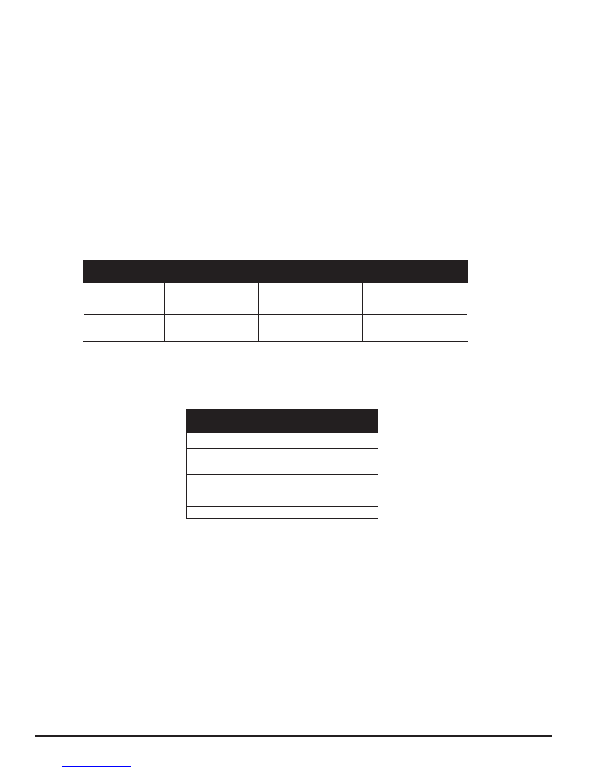
FLOOR PREPARATIONS
Covered Floors 6" [152mm] 6 1/8" [156mm]
(Carpet, Tile or
Wood)
Bare Concrete 6 1/16" [154mm] 6 1/8" [156mm]
or Terrazzo
FLOOR CORE CORE
TYPE SIZE (Min.) SIZE (Max.)
Step 3 Cr at cor hol according to th
dim nsions provid d in th chart.
2
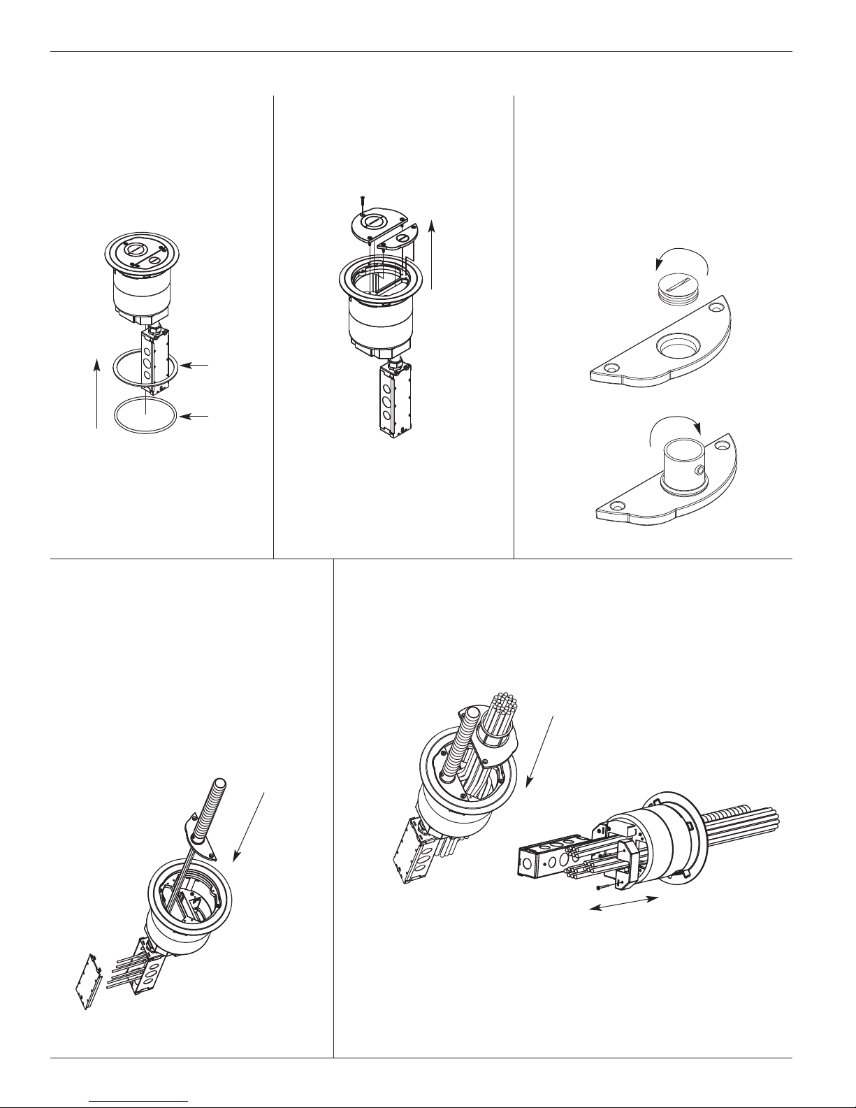
Step 2 R mov cov r plat s by
r moving (5) 8-32 scr ws.
Step 3 R mov 3/4" plug from small
cov r plat by rotating count r-
clockwis using a larg straight
blad scr wdriv r. Install 3/4"
conduit fitting (provid d) into
op ning on larg cov r. R p at
proc dur for 2" conduit fitting,
on larg cov r plat . (provid d)
NOTE: I necessary remove Feed Plates to pull communications wires through
Poke-Thru device. Replace Feed Plates when inished pulling wires.
Step 4 F d 3/4" inch fl xibl conduit
into 3/4" conduit fitting on cov r
plat . F d pow r wir s through
small compartm nt and into th
junction box. Mak wiring con-
n ctions in th junction box.
R f r to copp r cross s ction
chart to d t rmin quantity of
wir s to pass through ach op n-
ing. Attach cov r to th flang
using (2) 8-32 x 3/8" scr ws.
Step 5 F d data wir s through larg r compartm nt and through
2" conduit fitting on cov r plat . R f r to copp r cross
s ction chart to d t rmin quantity of cabl s to pass
through ach op ning. Attach cov r to th flang using
(3) 8-32 x 3/8" scr ws.
Step 1 Plac appropriat gask t
around Pok Thru and
slid und r flang . Us
flat foam gask t for til
applications or us round
n opr n gask t for
carp t applications.
Tile Gasket
Carpet
Gasket
INSTALLING COMPLETE ASSEMBLY
CAUTION: To maintain ire classi ication, Feed Plates must be installed.
NOTE: Splices must be made in junction box.
3
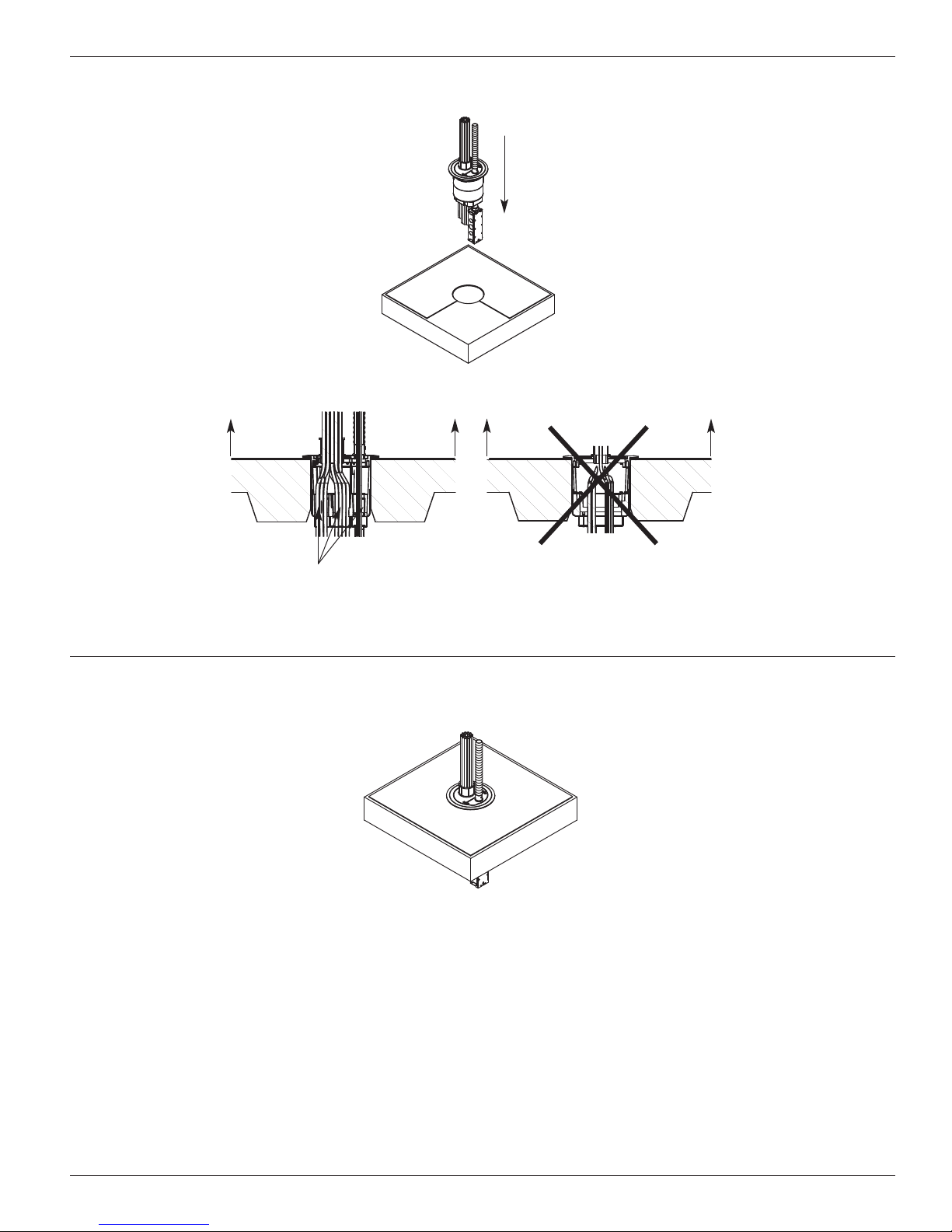
CAUTION: Cover must be removed to rotate Poke Thru once it has been installed in the loor.
Step 6 Ori nt Pok Thru so that th thr chann ls span across th corrugations of th d ck.
Push Pok -Thru into floor.
Device openings must
span across deck
Step 7 Installation compl t .
B BA A
4
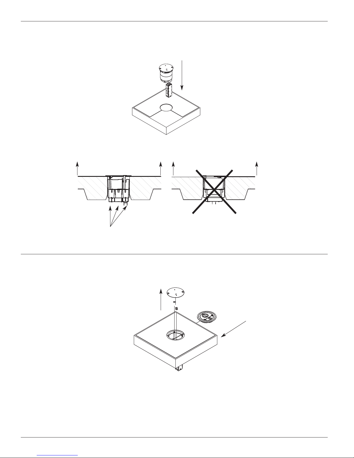
Device openings must
span across deck
CAUTION: Cover must be removed to rotate Poke Thru once it has been installed in the loor.
Step 1 Ori nt St m Ass mbly such that th thr chann ls span across th corrugations of th d ck.
Ins rt St m Ass mbly into cor hol .
Step 2 R mov disposabl plat and (2) plat clips by r moving th 8-32 scr ws. Install Flang using th
(2) 8-32 x 1/2" Cap H ad scr ws provid d with th cov r ass mbly.
INSTALLING STEM ASSEMBLY AND SEPARATE COVER
A A B B
5
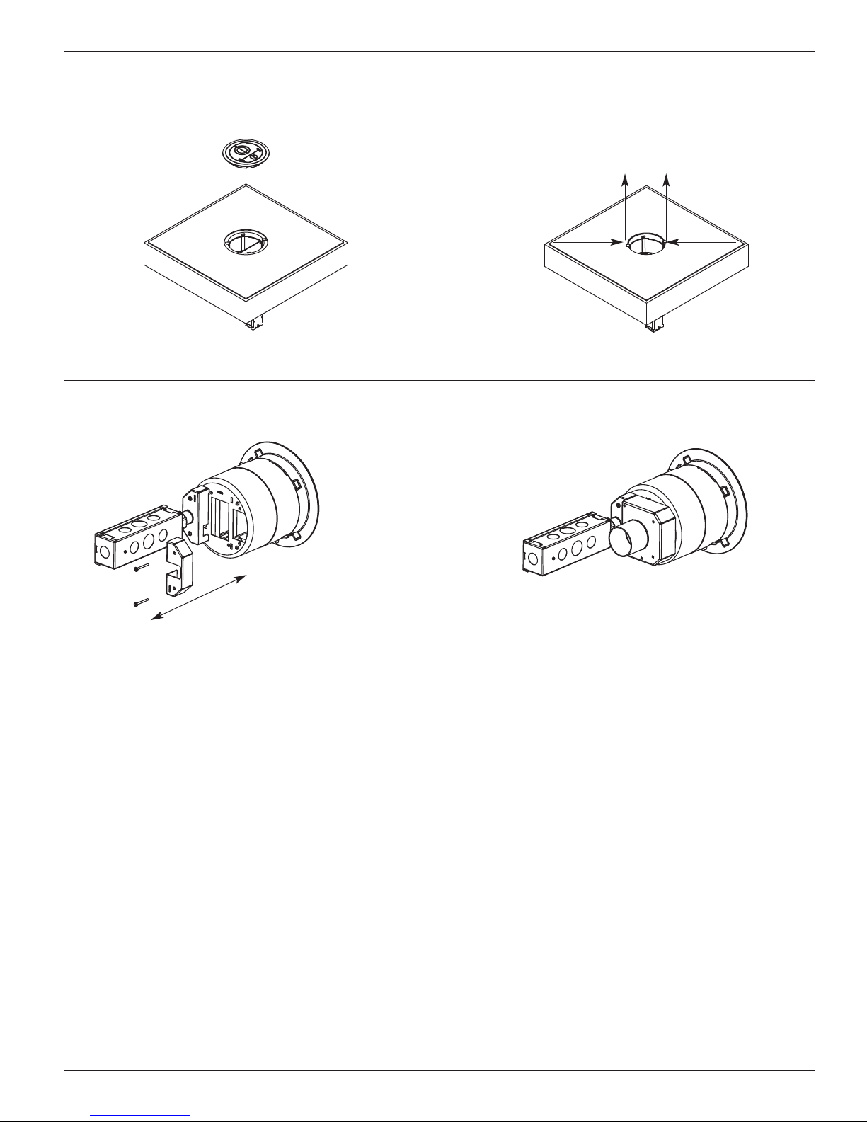
Step 2 R mov Pok Thru from floor by b nding
tabs inward and pulling unit up.
Step 1 R mov cov r ass mbly from Pok Thru by
rmoving (2) 8-32 scr ws and lifting cov r off.
CONFIGURING FEED PLATES
Step 4 Us (4) 8-32 scr ws to install n w f d plat
or housing.
Step 3 R mov (4) 8-32 scr ws and pull off
f d housings.
CAUTION: To maintain ire classi ication, Feed Plates
must be installed.
Evolution Series Poke-Thru Devices are UL Listed and Classi ied to U.S. and Canadian sa ety standards to the
ollowing conditions:
Th 6STC Pok -Thru St m with th 6CFFTC S rvic H ad Fitting, and th 6ATCFF factory ass mbl d Pok -Thru d vic ar
for us with 1-, 1 1/2 -, or 2- hour rat d unprot ct d r inforc d concr t floors and 1-, 1 1/2 -, or 2- hour rat d floors mploying
unprot ct d st l floor units and concr t topping (D900 S ri s D signs), or concr t floors with susp nd d c ilings. (Fir r sistiv
dsigns with susp nd d c ilings should hav provisions for acc ssibility in th c iling ar a b low th Pok -Thru fittings).
Th ass mbl d Pok -Thru st m and s rvic fitting will not r duc th ratings of th floor ass mbly wh n th thickn ss and typ
of concr t (r quir d for th sp cific rating) ar within th sp cifi d limits and th fittings ar install d as sp cifi d:
1. Spacing – Minimum of 2' [610mm] OC and not mor than on unit p r 65 sq. ft. [6 m2] of floor ar a in ach span.
2. Concrete – Minimum thickn ss of structural concr t topping of 2 1/4" [57mm] ov r m tal d ck or a minimum 3" [76mm]
thick r inforc d concr t slab. Unit w ight of concr t to b 110 to 155 pcf.
3. Installation – Mount d in a 6" [152mm] diam t r hol in concr t p r installation instructions accompanying
th fittings. For us with pow r circuits, data and/or audio/visual cabl s as tabulat d b low:
Th “TC” suffix l tt rs indicat that th d vic may b install d on til or carp t cov r d concr t floors.
6
Max Copp r .0815 sq. in. .0686 sq. in. .0187 sq. in.
X-S ction [52.6mm2] [44.3mm2] [12.1mm2]
Max # (10) 10 AWG (176) 23 AWG (48) 23 AWG
Conductors
POWER DATA CHANNEL DATA CHANNEL
CHANNEL (CENTER) (OUTSIDE)
COPPER CROSS-SECTION
Size Solid
#24 .00032 sq. in. [.20645mm2]
#22 .00050 sq. in. [.32258mm2]
#14 .00323 sq. in. [2.08386mm2]
#12 .00512 sq. in. [3.30321mm2]
#10 .00815 sq. in. [5.25805mm2]
#8 .01296 sq. in. [8.36127mm2]
Copper Cross Sectional Area
o Commonly Used Conductors
NOTE: When using conductor sizes other than listed above, the aggregate cross-sectional area o
the copper conductors shall not exceed the cross-sectional areas listed.
NOTE: Use above values or solid or stranded conductors.

7

WIREMOLD
U.S. and International:
60 Woodlawn Str t • W st Hartford, CT 06110
1-800-621-0049 • FAX 860-232-2062 • Outsid U.S.: 860-233-6251
Canada:
570 Appl wood Cr sc nt • Vaughan, Ontario L4K 4B4
1-800-723-5175 • FAX 905-738-9721
1 007 155 R1 0709
© Copyright 2009 Wir mold All Rights R s rv d
CAUTION: When printing copies o this
template please be sure template
is scaled correctly and is the
correct size once it is printed. Covered Floors 6" [152mm] 6 1/8" [156mm]
(Carpet, Tile or
Wood)
Bare Concrete 6 1/16" [154mm] 6 1/8" [156mm]
or Terrazzo
FLOOR CORE CORE
TYPE SIZE (Min.) SIZE (Max.)
Carpet Cutout
6 1/2" [166mm]
Carpet Cutout Template
Core Hole
(See chart below or
Core Hole dimensions.)
This manual suits for next models
6
Other LEGRAND Adapter manuals


