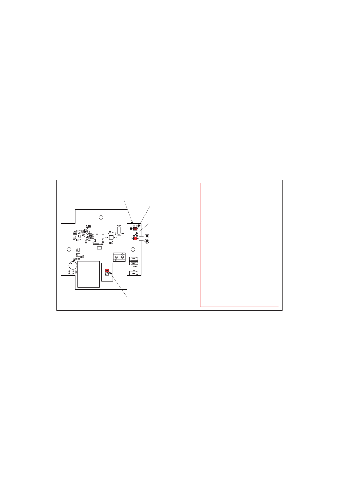
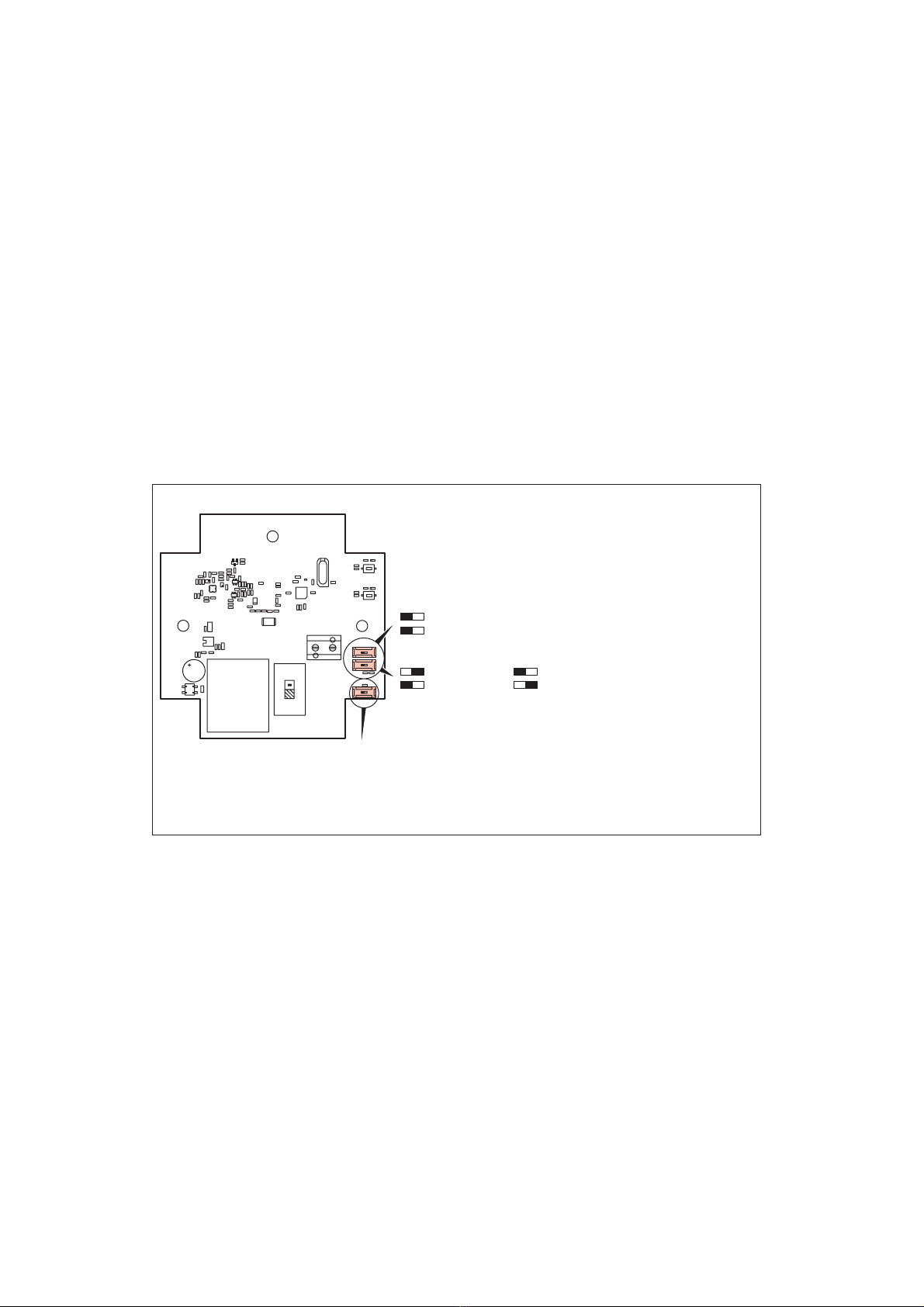
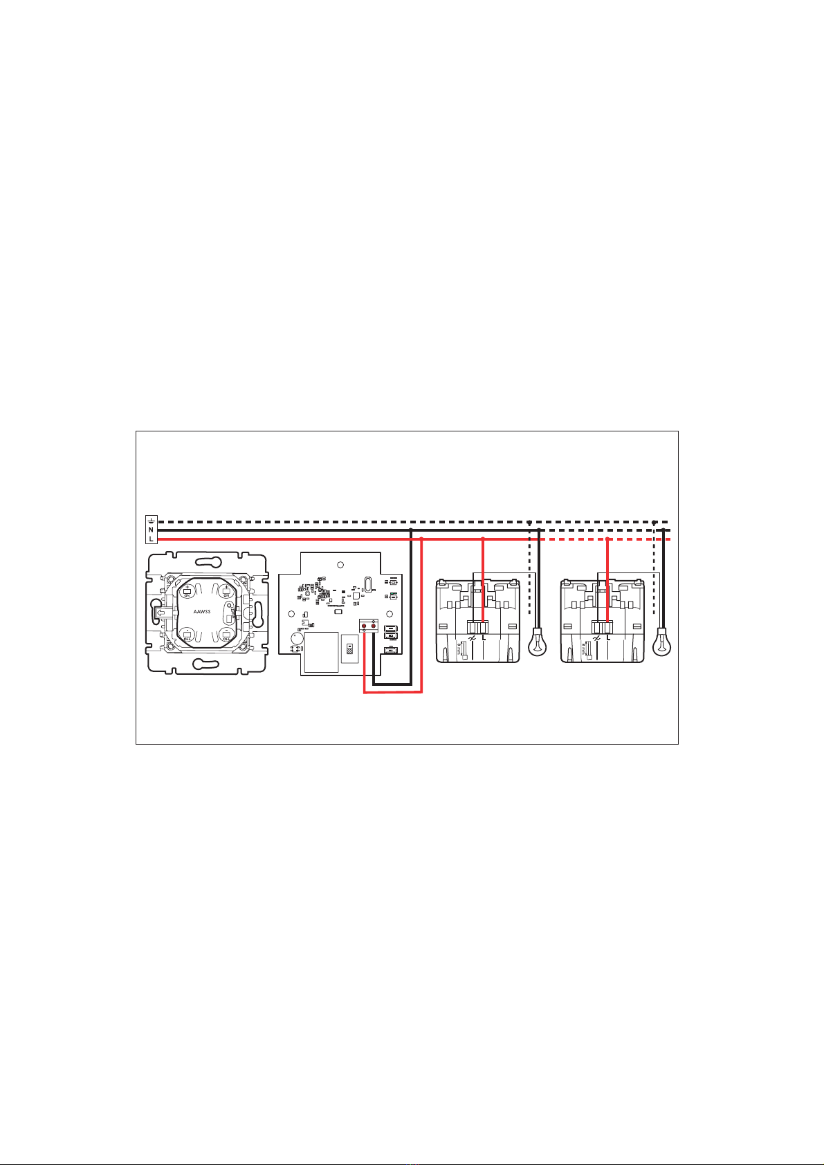
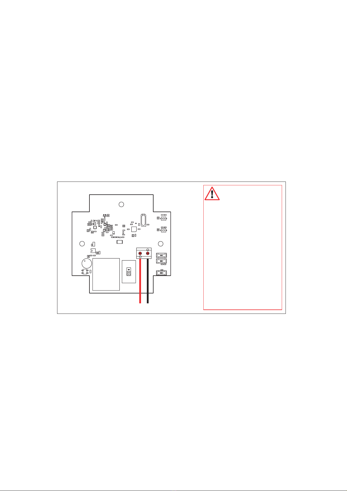
LEGRAND 916 50 User manual

RF repeater
916 50
Characteristics
N0064KR1/01
Supply 110 - 240 VA
50/60 Hz
2 x 1.5 mm²
approximately 200 m
in free field
- 20°C to + 65°C
Frequency
868.3 MHz
Radio
Range

2
LN
LN
Wiring
Safety instructions
This product should be installed in
line with installation rules, preferably
by a qualified electrician. Incorrect
installation and use can lead to risk of
electric shock or fire.
Before carrying out the installation, read
the instructions and take account of the
product’s specific mounting location.
Do not open up, dismantle, alter or mo-
dify the device except where specifically
required to do so by the instructions. All
Legrand products must be opened and
repaired exclusively by personnel trained
and approved by Legrand. Any unautho-
rised opening or repair completely can-
cels all liabilities and the rights to repla-
cement and guarantees.
Use only Legrand brand accessories.

3
Description
LN
Installation indicator light (blue: lit steadily
when the product is unlocked)
Learn indicator light
(green)
Learn key when first
pressed
100 - 230 V voltage selector
It acts as a control key
when pressed a second
time
Installation key (locking/
unlocking the repeater)
Factory set configuration
Once connected to the mains the
repeater only retransmits messages
received from transmitters in factory
mode.
Before installation:
To ensure that a transmitter is within
repeater range:
- unlock the repeater by pressing the
installation key,
- press one of the transmitter keys.
The installation indicator light (blue) blinks
if the repeater is at the correct distance

LN
4
Operation of the installation with one repeater
Choice of the position of the RF/ RF// switch:
It is advisable to leave the switch on RF// by default; this means that the radio messages are transmitted to the product’s
two aerials and improves the radiofrequency range between the repeater and the associated receivers.
However, in installations with numerous transmitters (>20), where a large number of radio messages can be transmitted at
the same time, it is advisable to reduce the number of these messages by moving the switch to RF/. This means that the
radio messages will only be sent to one of the two aerials.
Operation of the installation with two repeaters
Repeater 1 Repeater 2
Operation
The “In One by Legrand” RF repeater is used when the transmitter and
the radio receiver are too far apart for them to be able to communicate
with each other.

LN
5
Transmitter
Radio lighting scenario switch.
Receiver
300 W radio switch without neutral
Example of scenario creation.
Control switching on a switch without neutral with a scenario switch via a repeater.
Creation of a scenario in an installation with repeater
1) Unlock the repeater
2) Just like the other receivers, the repeater will be associated with transmitters by following the scenario learning, modi-
fication or deletion procedures. The correct operation (sufficient range, etc.) is checked by the state of the «LEARN”
indicator lights during this learning phase.
3) Lock the repeater (no action means that the product will be locked automatically after twenty minutes).
L1
RF repeater
E.g. 916 50

6
Operation (cont.)
Transmitter Receiver
LEARN
indicator
light
LEARN
indicator
light
L1
Legend
The indicator light
goes out
The indicator light
blinks slowly
The indicator light
blinks rapidly
The indicator
light flashes
Install./
LEARN
indicator
lights
Repeater
The indicator lamp
is lit

7
Operation (cont.)
Transmitter Receiver
LEARN
indicator
light L1
Repeater LEARN
indicator
light
Install./
LEARN
indicator
lights

8
Operation (cont.)
Check that the LEARN indicator light is
switched off, otherwise the receiver and
the repeater are too far apart.
Transmitter Receiver
LEARN
indicator
light L1
Repeater LEARN
indicator
light
Install./
LEARN
indicator
lights

9
Operation (cont.)
Example of scenario modification:
Run two switches without neutral
LN
Transmitter
RF lighting scenario switch
Receiver
RF switch without
neutral
300 W
L1
RF repeater
E.g. 916 50
L2
Receiver
RF switch without
neutral
300 W

10
Operation (cont.)
Open the
scenario
Receiver 1
Receiver 2
Transmitter Receiver
LEARN
indicator
light L1
Repeater LEARN
indicator
light
LEARN
indicator
light L2
Install./
LEARN
indicator
lights

11
Operation (cont.)
Receiver 1
Receiver 2
Receiver 2
Receiver 2
Transmitter Receiver
LEARN
indicator
light L1
Repeater LEARN
indicator
light L2
LEARN
indicator
light
Install./
LEARN
indicator
lights

12
Operation (cont.)
Transmitter Receiver
LEARN
indicator
light L1
Repeater LEARN
indicator
light L2
LEARN
indicator
light
Install./
LEARN
indicator
lights
Receiver 1
Receiver 2

Operation (cont.)
13
Return of the product to
factory configuration.
5 s
10 s
Return to factory mode
Erasing a transmitter known by the repeater.

14
PROBLEM CAUSE SOLUTION
The Learn indicator light comes on for
5 seconds.
Learning is impossible. Install compatible products.
The Learn indicator light comes on for
10 seconds.
The number of memorised transmitters
is greater than 32.
Delete unused scenarios.
The Learn indicator light no longer
blinks during learning.
The learning mode closes after 10
minutes (with no action).
Start learning again.
During learning, pressing the
programmed control key does not make
the Learn indicator light blink rapidly.
After pressing the Learn button once,
function key learning must be done
within the following minute.
Start learning again.
When the scenario is saved, the Learn
indicator lights of certain receivers do
not go out.
Poor communication between prod-
ucts.produits.
Reduce the distance between the
transmitter and the receivers(s), then
start learning again or add a repeater.
Operation (cont.)
To make sure that the repeater learns a control correctly, the blinking of the installation LED is noted for each RF message.

15
Funkverstärker
916 50
Technische Daten
Stromversorgung 110 - 240 VA
50/60 Hz
2 x 1,5 mm2
ca. 200 m im Freifeld
-20°C bis +65°C
Frequenz
868,3 MHz
Funksignal
Reichweite

1616
LN
LN
Verdrahtung
Sicherheitshinweise
Dieses Produkt darf nur durch eine
Elektro-Fachkraft eingebaut werden.
Bei falschem Einbau bzw. Umgang
besteht das Risiko eines elektrischen
Schlages oder Brandes.
Vor der Installation die Anleitung lesen,
den produktspezifischen Montageort
beachten.
Das Gerät vorbehaltlich besonderer,
in der Betriebsanleitung angegebener
Hinweise nicht öffnen, zerlegen, bes-
chädigen oder abändern. Alle Produkte
von Legrand dürfen ausschließlich von
durch Legrand geschultes und aner-
kanntes Personal geöffnet und repariert
werden. Durch unbefugte Öffnung oder
Reparatur erlöschen alle Haftungs-, Er-
satz- und Gewährleistungsansprüche.
Ausschliesslich Zubehör der Marke Le-
grand benutzen.

17
Beschreibung
LN
Installations-Leuchtdiode (blau / leuchtet
ständig, wenn das Gerät entsperrt ist)
Learn-Leuchtdiode (grün)
Learn-Taste beim ersten
Drücken
Spannungswahlschalter 100 - 230 V
Beim zweiten Drücken
hat sie die Funktion einer
Bedientaste.
Installations-Taste
(Sperrung/Entsperrung
des Verstärkers)
Werkseinstellung
Ab dem Anschluss an das Stromnetz
sendet der Verstärker nur die von den
Sendern im Werksmodus empfangenen
Funkmeldungen weiter.
Vor der Installation:
Um zu prüfen, ob ein Sender in der
Reichweite des Verstärkers liegt, ist
folgendermaßen vorzugehen:
- den Verstärker durch Drücken der
Installations-Taste entsperren,
- eine der Tasten des Senders drücken.
Liegt der Verstärker in der richtigen
Entfernung, blinkt die Installations-
Leuchtdiode (blau).

18
LN
Funktionsweise der Installation mit einem Verstärker
Wahl der Position des RF/ RF// Schalters:
Es wird empfohlen, den Schalter defaultmäßig auf RF// zu lassen, d.h. die Funkmeldungen werden über die beiden Antennen
am Gerät übertragen, was die Funkreichweite zwischen dem Verstärker und den dazugehörigen Empfängern erhöht.
In Installationen mit einer großen Anzahl von Sendern (>20), in denen gleichzeitig eine große Zahl von Funkmeldungen
gesendet werden können, ist es wünschenswert, die Zahl dieser Meldungen durch Positionieren des Schalters auf RF/ zu
reduzieren. D.h. die Funkmeldungen werden nur über eine der beiden Antennen gesendet.commutateur sur RF/.
Funktionsweise der Installation mit zwei Verstärkern
1. Verstärker 2. Verstärker
Funktionsweise
Der „In One by Legrand“ Funkverstärker wird benutzt, wenn die
Entfernung zwischen dem Funksender und -empfänger für die
Funkverbindung zu groß ist.

19
LN
Sender
Funk-Beleuchtungsszenarioschalter.
Empfänger
300 W Funkschalter ohne Nullleiter
Beispiel für die Erstellung eines Szenarios
Einschaltsteuerung eines Funkschalters ohne Nullleiter mit einem Funk-Szenarioschalter über einen Verstärker.
Erstellung eines Szenarios in einer Installation mit Verstärker
1) Den Verstärker entsperren.
2) Der Verstärker wird genau wie die anderen Empfänger durch Abwicklung der Abläufe zum Einlernen, Ändern oder
Löschen eines Szenarios mit den Sendern verknüpft. Die Kontrolle der ordnungsgemäßen Funktion (ausreichende
Reichweite, usw.) wird durch den Status der LEARN-Leuchtdioden während dieser Einlernphase gewährleistet.
3) Den Verstärker sperren (bei Nichtbetätigung erfolgt die Sperrung des Geräts automatisch nach 20 Minuten).
L1
Funkverstärker
z.B.: 916 50

20
Funktionsweise (Fortsetzung)
Sender Empfänger L1
Zeichenerklärung
Die Leuchtdiode
erlischt.
Die Leuchtdiode
blinkt langsam.
Die Leuchtdiode
blinkt schnell.
Die Leuchtdiode
leuchtet auf.
Verstärker
Die Leuchtdiode
leuchtet.
LEARN-
Leucht -
- diode
LEARN-
Leucht -
- diode
Inst./
LEARN-
Leucht -
- dioden
Other manuals for 916 50
1
Table of contents
Other LEGRAND Repeater manuals