Leine & Linde 800 Series User manual

Programmable Overspeed
Monitor
FOR 800 SERIES, 1000 SERIES AND GATEWAY
MANUAL / USERS GUIDE

Leine &Linde AB
T +46-(0)152-265 00
F +46-(0)152-265 05
www.leinelinde.com
Version: 1.0
Publication date: 2016-07-19

Programmable Overspeed Monitor
USER MANUAL www.leinelinde.com
3
Contents
1 INTRODUCTION ______________________________________________________________ 4
1.1 ABOUT PROGRAMMABLE OVERSPEED MONITOR ______________________________________________________ 4
1.2 ABOUT 800 SERIES __________________________________________________________________________________ 4
1.3 ABOUT 1000 SERIES _________________________________________________________________________________ 4
1.4 ABOUT ENCODER GATEWAY _________________________________________________________________________ 5
1.5 TECHNICAL AND COMMERCIAL SUPPORT ____________________________________________________________ 5
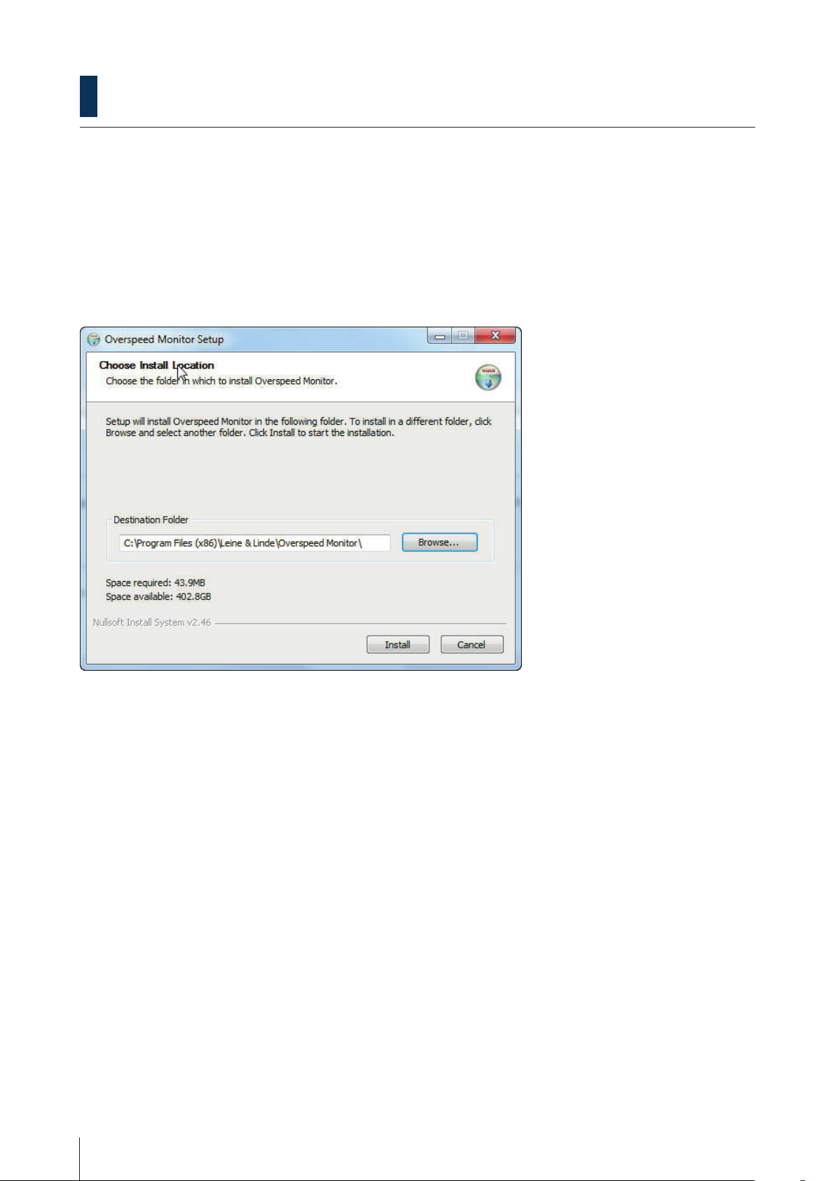
2 INSTALLING THE SOFTWARE _________________________________________________ 6
2.1 DOWNLOAD AND INSTALL THE SOFTWARE __________________________________________________________ 6
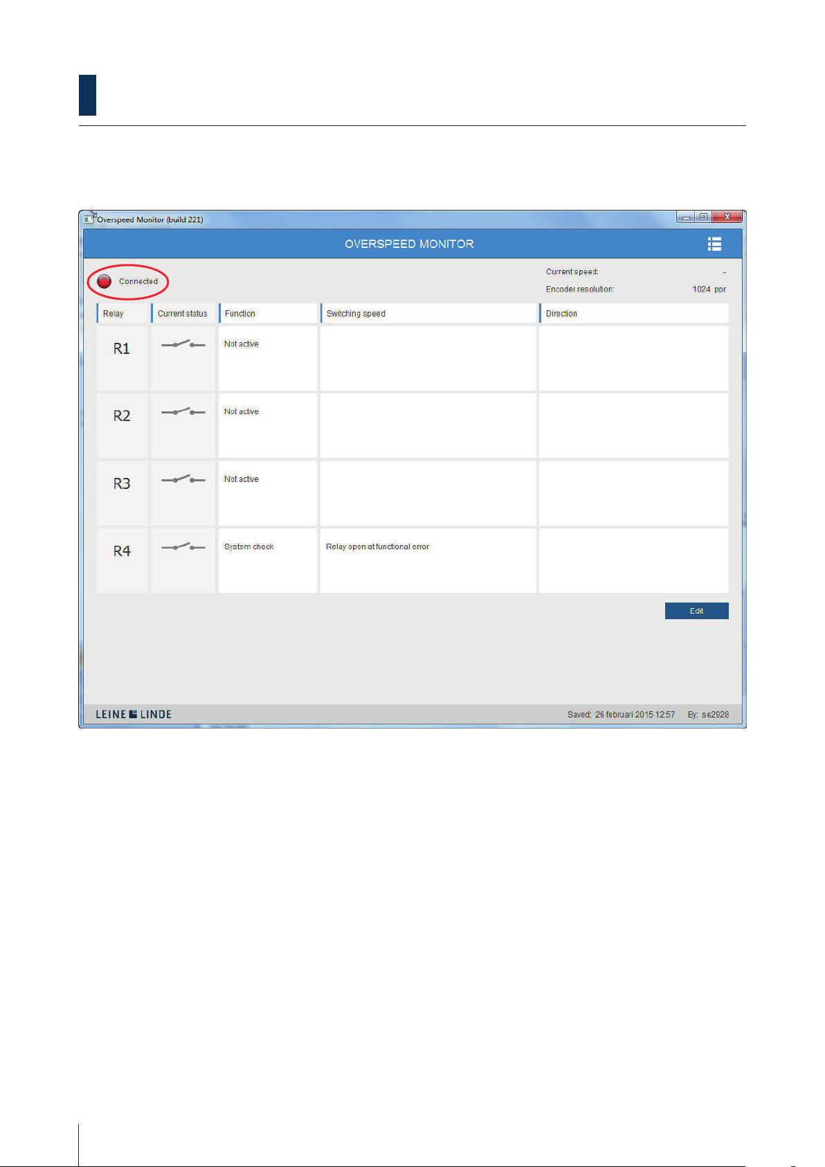
3 FUNCTIONAL DESCRIPTION __________________________________________________ 7
3.1 DIGITAL LED ________________________________________________________________________________________ 7
3.2 CURRENT SPEED ____________________________________________________________________________________ 9
3.3 RELAYS ____________________________________________________________________________________________ 10
3.4 CURRENT STATUS__________________________________________________________________________________ 11
3.5 FUNCTION ________________________________________________________________________________________ 12
3.6 SWITCHING SPEED_________________________________________________________________________________ 14
3.7 DIRECTION ________________________________________________________________________________________ 17
3.8 RESOLUTION ______________________________________________________________________________________ 18
3.9 EDIT, SAVE, CANCEL________________________________________________________________________________ 19
3.10 TOOL MENU ______________________________________________________________________________________ 20
3.11 CONFIGURATION _________________________________________________________________________________ 21
3.12 MANUAL _________________________________________________________________________________________ 22
3.13 HELP _____________________________________________________________________________________________ 22
4 APPENDIX __________________________________________________________________ 23
4.1 CONNECTING THE DEVICES FOR PROGRAMMING THE OVERSPEED SETTINGS__________________________ 23
4.2 ACCESSORIES ______________________________________________________________________________________ 23
5 REVISION HISTORY _________________________________________________________ 24
Leine&Linde AB claims copyright on this documentation. This documentation may not be modified,
extended or passed onto to a third party and/or copied without written approval from Leine&Linde AB.
Specifications and content in this document are subject to change without prior notice due to our
continuous efforts to improve the functionality and performance of our products.

Programmable Overspeed Monitor
USER MANUAL www.leinelinde.com
4
1 Introduction
1.1 About Programmable Overspeed Monitor
Leine& Linde’s Programmable Overspeed Monitor is a speed detection system that can be integrated in an en-
coder or a gateway together with a separate input from an incremental encoder. It features four different relay
switches which can be manually programmed for optional switching speeds. One of the relays can be set to
detect any functional error in the overspeed unit.
The overspeed unit is programmed with the help of a PC-software. Connection for programming is made via a
cable with USB to Mini USB connector.
The relays may be connected to maximum 30 Vdc and 2 A.
1.2 About 800 series
The 800 is an extreme robust encoder series which
comes in various mechanical solutions, hollow shaft
or solid shaft.
With the programmable overspeed integrated into
the encoder and accessed by a mini-USB through an
opening in the rear cover, it is easy configurable when
installed or before installation.
1.3 About 1000 series
The 1000-series is designed to meet exceptional re-
quirements in real heavy duty application.
With sturdy bearings and enclosure the 1000-series
encoders achieve extraordinary durability towards
mechanical stress, shock and vibrations as well as
dusty environments with high temperatures.

Programmable Overspeed Monitor
USER MANUAL www.leinelinde.com
5
1.4 About encoder gateway
The advantages of the gateway concept is that it
allows the use of small and very robust incremental
encoders, which make the encoder gateway solution
suitable in applications where there are space or
mechanic limitations.
The programmable overspeed encoder gateway is
compatible with 6 channels HTL or HCHTL encoders
within the 500, 700 and 800 series (except for FSI 800)
but is typically combined with an encoder with two
separate outputs, one for feedback to the motor drive
system, and the other connected to the gateway itself
to control wether speed reaches the critical levels.
1. Dual encoder with two galvanically insulated
outputs.
2. Incremental signal for drive system
3. CRG Overspeed
4. Relay output for overspeed or function alarm
5. Power supply
1.5 Technical and commercial support
Leine& Linde are represented by subsidiaries in many countries around the world. In addition, there are many
services agencies and distributors located worldwide ready to reply to commercial enquires or technical support.
For more contact information, please visit our web site or contact Leine &Linde in Strängnäs, Sweden.
Leine& Linde AB
Box 8
SE-645 21 Strängnäs, Sweden
Tel: +46-(0)152-265 00
Fax: +46-(0)152-265 05
E-mail: [email protected]
Web: www.leinelinde.com
5
4
2
1
3

Programmable Overspeed Monitor
USER MANUAL www.leinelinde.com
6
2 Installing the software
2.1 Download and install the software
System requirements: Windows Vista, XP, 7 or 8.
Download the programmable overspeed PC-software from the website: www.leinelinde.com.
Follow the instructions given to install the PC-software.
To be able to identify the encoder on the PC-software an FTDI driver might need to be installed. This can be
found in the Leine & Linde folder: Program files/leine & Linde/Overspeed Monitor (CDM21216_setup).

Programmable Overspeed Monitor
USER MANUAL www.leinelinde.com
7
3 Functional description
A description of each available feature in the overspeed unit is made in this chapter. The title of each section in
the text below refers to a graphical element in the PC software.
3.1 Digital LED
In the top left corner of the PC software a digital LED indicates the status of the overspeed unit. A green LED
indicates that the overspeed unit is powered and fully operational. A red LED indicates an error or that only the
programming mode is active. If the LED is grey, the unit is not connected to the PC or no serial port has been
chosen.
For the overspeed function to be operational (green LED) the unit needs to be powered via an external power
source of 9-30 Vdc.

Programmable Overspeed Monitor
USER MANUAL www.leinelinde.com
8
For using the device in programming mode (red LED) only, it is enough to power the unit via the USB connection.
Note that in the programming mode the unit is not able to detect the current speed or operate the switches.
A red LED may also indicate that a functional error is detected in the overspeed unit. If R4 is set to alarm mode
the relay will open and an error description will be given on the R4 row.

Programmable Overspeed Monitor
USER MANUAL www.leinelinde.com
9
3.2 Current speed
The value in the top right corner indicates the current speed and direction of rotation of the shaft. This can be
used as a help to test settings when configuring the unit. The shaft speed is expressed in revolutions per minute
(rpm) and the direction of rotation as clockwise (CW) or counter-clockwise (CCW) seen from encoder shaft end.
The encoder resolution is shown below the current speed. In case of use of a separate overspeed gateway, this
field is empty by default. Enter the encoder resolution value by using edit mode (see chapter 3.8-3.9).

Programmable Overspeed Monitor
USER MANUAL www.leinelinde.com
10
3.3 Relays
The overspeed unit has four output relays R1-R4, each configurable with its own separate settings. By clicking
Edit the switching speed can be manually programmed to switch state at a desired rotational speed and direc-
tion of rotation.
The relay R4 is by default set to alarm mode and will then open in case of functional error. To use R4 as relay
for switching speed, fill in the desired values and settings and press save. To again use the R4 as alarm relay,
press deactivate button and press save.

Programmable Overspeed Monitor
USER MANUAL www.leinelinde.com
11
3.4 Current status
The Current status column shows the current state, open or closed, for each of the four relays. The symbols
will switch state when the relays do, and can therefore be used for verification of the settings.

Programmable Overspeed Monitor
USER MANUAL www.leinelinde.com
12
3.5 Function
Relays R1-R4 can be configured with overspeed or underspeed function.
The overspeed option means the relay will be closed at low speeds and open at high. It switches at rising speed
and switches back when the speed is decreased to a level -10% below the switching speed.
The underspeed option means the relay will be closed at high speeds and open at low. It switches at falling
speed and switches back when the speed is increased to a level +10% above the switching speed.
Relay R4 can alternatively be set into alarm mode (default) and will then monitor the function of the overspeed
unit. It is normally closed and will open if a functional error is detected. An error description will be given on
the R4 row.
Error descriptions
R1 do not open
R1 do not close
R2 do not open
R2 do not close
R3 do not open
R3 do not close
Internal error

Programmable Overspeed Monitor
USER MANUAL www.leinelinde.com
13
If the overspeed unit is not powered, the relays stay open, independently of the settings. Therefore, if the relays
do not close when expected to, the power source is a possible fault cause.

Programmable Overspeed Monitor
USER MANUAL www.leinelinde.com
14
3.6 Switching speed
In the Switching speed boxes, the desired switching levels are configured. Any integer between 0 and 6000 rpm
can be set. When using the overspeed setting, the relay will open when the current speed rises above the se-
lected level (>). When using the underspeed setting, the relay will open when it falls below (<).
To be able to ignore very short speed peaks the averaging interval time can be set to a value 50 – 1000 ms, see
chapter 3.11 configuration

Programmable Overspeed Monitor
USER MANUAL www.leinelinde.com
15
If set to 0 rpm a standstill indication is created. The relay will be closed at 0 rpm and open at movement (if
combined with the overspeed setting), or closed at movement and open at standstill 0 rpm (if combined with
the underspeed setting).
Note: The overspeed function is not active until the user has set the values and saved the changes.

Programmable Overspeed Monitor
USER MANUAL www.leinelinde.com
16
To deactivate a relay, click deactivate button.

Programmable Overspeed Monitor
USER MANUAL www.leinelinde.com
17
3.7 Direction
The Direction option configures how the switching speed should be activated. With option CW/CCW switching
speed is activated independently of the shaft rotation direction. With option CW it is activated only at clock-
wise rotation, and with option CCW only at counter-clockwise rotation.
When choosing underspeed, the direction is automatically always set to both directions.
Note: The overspeed function is not active until the user has set the direction and saved the changes.

Programmable Overspeed Monitor
USER MANUAL www.leinelinde.com
18
3.8 Resolution
When programming an encoder with integrated overspeed, the resolution is automatically shown in the resolu-
tion field. When programming a gateway, the resolution of the encoder in use must be entered in this field.

Programmable Overspeed Monitor
USER MANUAL www.leinelinde.com
19
3.9 Edit, Save, Cancel
The starting view of the program provides an overview of the active settings. To configure the settings click Edit
to enter the programming mode.

Programmable Overspeed Monitor
USER MANUAL www.leinelinde.com
20
After editing, click Save in order to activate the changes and exit the programming mode. Click Cancel to exit
the programming mode without saving changes.
In the bottom right corner, the date and time for when the file was last saved is shown, as well as by which
user (the computer user login) it was saved.
3.10 Tool menu
In the top right corner there is a tool menu. Click the icon and you will have three choices:
• Configuration
• Manual
• Help
This manual suits for next models
1
Table of contents
Popular Measuring Instrument manuals by other brands

Bosch
Bosch GLM 100-25 C Original instructions

Agilent Technologies
Agilent Technologies ESA-E E4402B Configuration guide

York Survey Supply
York Survey Supply 343660 operating instructions

palintest
palintest Micro 600 manual

sauter
sauter CD P2 Data Sheet and Instruction Manual

Klein Tools
Klein Tools CL220 instruction manual