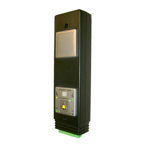
Leitronic AG LMK70-ATEX User manual

ATEX-manual for units
LMK70-ATEX (Zone 0)
LMK70-ATEX (Zone 0/20)
ATEX-Barrier
Issue 6.2013 | Version 1-0
Generic installation directive accordin to
EN60079-14 (Gas)
EN60079-17 (Maintenance Gas)
EN60079-19 (Reparation)
EN61241-14 (Dust)
EN61241-17 (Maintenance Dust)
Since LMK70-ATEX is intrinsically safe,
installation and maintenance can be carried out,
even with applied as atmosphere

Table of contents
ATEX: Component overview
...................................................................................................................................... 3
Sub-communication-unit: LMK70-ATEX Zone 0
.................................................................................................. 3
Panels
.............................................................................................................................................................. 3
Drillin hole proposal for new panels
........................................................................................................... 4
Housin for sub-communication unit: Zone 0 only
............................................................................................ 5
EA-IP-EN70-EC incl. emer ency button RT42 (bell, NO/NC
.............................................................................. 5
Artikel-Nr:: 100.0730
........................................................................................................................................... 5
Housin
................................................................................................................................................................. 5
Dimension 180 x 110 x 64 mm
............................................................................................................................ 5
Feed throu h 1 x M16 incl 3M-RJ45-cable
......................................................................................................... 5
Protection EN 60529 IP 54
.................................................................................................................................. 5
Wei ht 410 (without sub-communication unit)
.............................................................................................. 5
Sub-communication-unit: LMK70-ATEX Zone 0/20
............................................................................................ 5
Emer ency-button (Surface version): NT-ATEX-AP
..................................................................................... 5
Emer ency button (Built-in version): NT-ATEX-EB
...................................................................................... 5
Components outside ATEX-Zone
............................................................................................................................... 6
ATEX-Barrier:
........................................................................................................................................................ 6
Supply
................................................................................................................................................................... 7
Interruptible power supply USV-230VAC-12V-IP
............................................................................................... 7
DIN-adapter (DIN-Rail: 1 unit)
..................................................................................................................... 7
UPS interface EA-NSG (DIN-Rail: 1 unit)
..................................................................................................... 7
12V-battery
..................................................................................................................................................... 7
Wirin
......................................................................................................................................................................... 8
With Leitronic diallers
.......................................................................................................................................... 8
With third party diallers
...................................................................................................................................... 9
Usin two sub-communication-units (NC type)
............................................................................................... 11
Usin two sub-communication-units (NO type)
............................................................................................... 12
Declaration of Conformity
....................................................................................................................................... 13
EC-Type Examination Certificate
............................................................................................................................ 14
2

ATEX: Component overview
S b-comm nication- nit: LMK70-ATEX Zone 0
The sub-communication unit LMK-ATEX permits alarm tri ered by external
emer ency button and hands-free connection.
EN81-70 symbols (yellow/ reen) over li ht-pipes to front-panel.
Order-No. 121.0370
S pply
Primary volta e max. 5.9V DC
Power consumption 90 mW
Safety degree
II 1 G Ex ia IIC T4 Ga
Inp t-/O tp t
ATEX Connection with ATEX-Barrier optional:
- 10 pole cable
- RJ45 shielded
EC Connection with external emer ency button
(Normally closed NC)
Symbols
EN81-70 Phone (yellow) / Speak ( reen) li ht pipes to panel
Environment conditions
Operation temperature 0 ° to 40 °C
Humidity 20 % - 70 % relative humidity, non condensin
Ho sing
Dimension 111 x 55 x 21 mm (B x H x D)
120 x 75 x 21 mm (B x H x D)
Incl. feed throu h and button
Wei ht 91
Panels
For surface / wall-mountin of communication units LMK70-ATEX Zone 0
Artikel-Nr: 100.0220 EA-TAB 100.0221 EA-TAB-NT 100.0231
without button with button RT-42 2M / Typ XI transparent frame
Dimension: 200 x 100 x 2 mm 200 x 100 x 2 mm 220 x 100 x 23 mm
Material: INOX INOX PMMA
Wei ht: 320 340 180
Delivery includin mountin -screws and li ht-pipes for EN70-symbols
3

Drilling hole proposal for new panels
Drillin hole proposals from Schäfer GmbH with the appropriate order code.
In addition, two external EN81-70 indicators: e. . Type MA42 (shepherds) or similar. The built-in LED LMK7x
LEDs and two li ht pipes (Art. No: 25 145 PGN) will lead li ht to the front: hole diameter Ø = 2.6-0.05mm.
Option 1: "G9924"
Option 2: "G9924 LMK70 LED" with holes for li ht pipes and en ravin
Option 1: "G9924w " waterproof drillin pattern => use EA-LMK70B-WG to achieve IP54
Option 2: "G9924w LMK70 LED" with holes for li ht pipes and en ravin
Option 1: "G4824"
Option 2: " G4824 LMK70 LED" with holes for li ht pipes and en ravin
4

Ho sing for s b-comm nication nit: Zone 0 only
EA-IP-EN70-EC incl. emer ency button RT42 (bell, NO/NC
Artikel-Nr:: 100.0730
Ho sing
Dimension 180 x 110 x 64 mm
Feed throu h 1 x M16 incl 3M-RJ45-cable
Protection EN 60529 IP 54
Wei ht 410 (without sub-communication unit)
S b-comm nication- nit: LMK70-ATEX Zone 0/20
The sub-communication unit LMK-ATEX permits alarm tri ered by internal
emer ency button and hands-free connection.
Built-in EN81-70 symbols (yellow/ reen).
External emer ency-button connectible.
Order-No. 121.0380
Safety degree
II 1 GD Ex ia IIC T4 Ga
Ex ia IIIC T50 °C Da IP64
Inp t-/O tp t
Cable 1 Connection with ATEX-Barrier optional:
- 10 pole cable
- RJ45 shielded
Cable 2 Connection to external emer ency button.
NT-ATEX-AP, NT-ATEX-EB
Environment conditions
Operation temperature 0 ° to 40 °C
Humidity 20 % - 70 % relative humidity, non condensin
Ho sing
Dimension 160 x 160 x 91 mm (L x W x H)
188 x 160 x 109 mm (L x W x H), with PG11 and button
Feed throu h 3 x PG11 (Round cable - = 5.5 to 8.5 mm)
Wei ht 1750
Emergency-b tton (S rface version): NT-ATEX-AP
Additional emer ency button (normally open) on top or below the cabin.
Order-No. 121.0322
Safety degree
ATEX Zone 1&2 , 21&22 Gas: Ex II 2 G EEx ed IIC T6
Dust: Ex II 2 D IP66 T80°C
Inp t-/O tp t
Cable 1 Connection to or sub-communication-unit
Environment conditions
Operation temperature -20 ° to 40 °C
Ho sing
Dimension 80 x 123 x 90 mm (L x W x H)
Feed throu h 1 x M16 ( Round cable - = 4 to 9 mm)
Wei ht 370 (completely mounted/without connection cable)
Emergency b tton (B ilt-in version): NT-ATEX-EB
Additional emer ency button (normally open) on top or below the cabin.
Order-No. 121.0323
Safety degree
ATEX Zone 1&2 , 21&22 Gas: Ex II 2 G EEx ed IIC T6
Dust: Ex II 2 D Ex tD A21 IP65 T80°C
5
1 2 3
Cable

Inp t-/O tp t
Cable 1 Connection to or sub-communication-unit
Environment conditions
Operation temperature -20 ° to 60 °C
Ho sing
Dimension 148 x 38 mm (L x ) Monta e- = 30.5 mm
Without the rear part len th is 90mm. Usin so the
emer ency button must be mounted in a secure
housin !!
Feed throu h 1 x M16 ( Round cable - = 4 to 9 mm)
Wei ht 140
Components o tside ATEX-Zone
ATEX-Barrier:
Order-No. 121.0390
S pply
POWER 3pol pluggable/screw terminal
IN1+ / IN2+ / GND
Supply voltage 8 - 35 DC
Nominal power Max. 4 W
Safety degree
II (1) GD [Ex ia] IIC
[Ex ia] IIIC
Inp t-/O tp t
ATEX to sub-communication unit LMK70-ATEX, optional
- pluggable/screw terminal : 10pol cable
- RJ45 shielded
EXT to Leitronic-diallers
For third party products
AUDIO 3pol pluggable/screw terminal to:
MIC+ / GND / LS+
UNI 10pol pluggable/screw terminal to:
HORN max. 24 V / 50mA normally open (60Ohm)
EC max. 24 V / 50mA normally open (60Ohm)
PHONE max. 24 V active with si nal
SPEAK max. 24 V active with si nal
READY max. 24 V / 50mA normally closed (60Ohm)
Indicators
EN81-70 Phone (yellow) / Speak ( reen)
STATE reen Phone/Speak connected
blue Speaker/Microphone connected
Environment conditions
Operation temperature -20 ° to 60 °C
Ho sing
Dimension 45 x 118 x 138 mm
Wei ht 340
6

S pply
Interr ptible power s pply USV-230VAC-12V-IP
Order-No. 121.0117
Order-No: 100.0117+ 118.0117 + 100.0880 mounted in IP65 housin
Dimension 110 x 110 x 90 mm (L x W x H)
DIN-adapter (DIN-Rail: 1 nit)
Order-No. 118.0117 118.0118
Primary volta e 230 V AC/50 Hz 16 – 35 V DC
Secondary volta e 14.3 V DC
UPS interface EA-NSG (DIN-Rail: 1 nit)
Order-No. 100.0117
Primary volta e 14.3 V DC
Backup with 12 V-battery I.e. 100.0880
Output permanent 12 V DC 400 mA for ATEX-Barrier & dialler
switched 12 V DC 200 mA for emer ency li ht
12V-battery
Order-No. 100.0880
Volta e 12 V DC
Capacity 1.2 Ah
7

Wiring
With Leitronic diallers
1. Mount LMK70-ATEX
Zone 20 121.0380: Connect round-terminal with earth
Zone 0 121.0370: Connect emer ency button to terminal EC
2. Connect ATEX-Barrier EARTH to Earth
3. Connect LMK70-ATEX and ATEX-Barrier usin either
a) RJ45 shielded
b) 10 pole cable
10poli RJ45 Markin Information
1,4,7,10 1,8 AGND Ground
2 3 APHONE Symbol Phone
3 6 ASPEAK Symbol Speak
5 4 AMIC+ Microphone differential +
6 5 AMIC- Microphone differential -
8 2 AEC Emer ency button
9 7 ALS Loudspeaker
4. Connect EXT-ports of ATEX-Barrier and dialler Exicall EN70/EasyAlarm
usin RJ45-cable
5. Connect LINE of dialler Exicall EN70/EasyAlarm with analo ue telephone
line (PSTN( usin RJ12-cable
6. Optional: connect alarm horn (Example powered by VIN)
7. Connect uninterupted power supply to POWER: 8 to 35 V DC / max 4 W
i.e. usin EA-NSG (100.0117)+ 12V-battery (100.0880) and..
8. Supply volta e from DIN-adapter
a) 118.0117 => 230 V AC / 50Hz
b) 118.0118 => 16 – 35 V DC
8
4.
5.
3.
6.
1.
8.
2.
7.

With third party diallers
1. Mount LMK70-ATEX
Zone 20 121.0380: Connect round-terminal with earth
Zone 0 121.0370: Connect emer ency button to terminal EC
2. Connect ATEX-Barrier EARTH to Earth
3. Connect LMK70-ATEX and ATEX-Barrier usin either
a) RJ45 shielded
b) 10 pole cable
10poli RJ45 Markin Information
1,4,7,10 1,8 AGND Ground
2 3 APHONE Symbol Phone
3 6 ASPEAK Symbol Speak
5 4 AMIC+ Microphone differential +
6 5 AMIC- Microphone differential -
8 2 AEC Emer ency button
9 7 ALS Loudspeaker
4. Connect Inputs/Outputs between dialler and UNI-port of ATEX-Barrier
PIN Markin max. volta e max. current Specification
1 HUPE 24V 50 mA Potential free contact (60Ohm) closes as lon as
emer ency button on LMK70-ATEX is pressed
2 HUPE
3 EC 24V 50mA Potential free contact (60Ohm) closes as lon as
emer ency button on LMK70-ATEX is pressed
Same round as Audio-Port
4 GND
5 SPEAK(+) 24V 25mA Si nal input: active from 6 to 24 V DC
6 SPEAK(-)
7 PHONE(+) 24V 25mA Si nal input: active from 6 to 24 V DC
8 PHONE(-)
9
4.
5.
6.
7.
3.
1.
2.

9 READY 24V 50mA Contact (60Ohm) is closed when LMK70-ATEX is ready.
Same round as Audio-Port
10 GND
5. Connect microphone/speaker between dialler and AUIDO of ATEX-Barrier
PIN Markin max. volta e max. current Specification
1 MIC+ Microphone Adjust level usin MIC_VOLUME
2 GND Same round as READY
3 LS+ Loudspeaker Adjust level usin LS_VOLUME
6. Connect dialler to telephone line (PSTN)
7. Connect uninterupted power supply to POWER: 8 to 35 V DC / max 4 W
10

Using two s b-comm nication- nits (NC type)
Standard (cable break would be re istered)
Optional:
Normally closed button in pit (ATEX-Zone)
loop in AEC wire of cable
11
NC
NC

Using two s b-comm nication- nits (NO type)
Better use NC version as cable break would not be re istered (NO)
Optional:
Normally open button in pit (ATEX-Zone)
connect between PIN AEC and AGND of 10-wire cable
12
NO
NO

Declaration of Conformity
Accordin to the ATEX Directive 94/9/EC of 23.March 1994
Manufacturer’s Name: Leitronic AG
Manufacturer’s Address: En eloostrasse 16
CH-5621 Zufikon, Switzerland
declares that the product
Product Name: LMK70-ATEX (121.0370 / 121.0380)
ATEX-Barrier (121.0390)
conforms to the followin standards:
EN 60079-0
EN 60079-11
EN 60079-26
S pplementary Information
The product herewith complies with the requirements of the followin Directives
and carries the CE markin accordin ly:
the EMC directive 2004/108/EC
Zufikon, 24. May 2013 Silvan To nella
13

EC-Type Examination Certificate
14

15

16
Table of contents
Other Leitronic AG Intercom System manuals