88
88
8
Spare Part ListSpare Part List
Spare Part ListSpare Part List
Spare Part List
LegendLegend
LegendLegend
Legend
EU = Europe Version 230Vac
US = United States Version 115Vac
Code Description
AccessoriesAccessories
AccessoriesAccessories
Accessories
277349 Owner’s Manual (Italian-English)
130297 Mains Cable (EU)
130283 Mains Cable (US)
AssemblyAssembly
AssemblyAssembly
Assembly
667731 Cover
667729 Chassis
667728 Front Panel
657279 Display Screen
657277 Meters Screen
347060 Nylon Cable Tie with 3mm Eye
340961 Encoder Knob
340186 Adhesive Cable Fixing
340078 TO220 Insulated Bush
210215 Adhesive Rubber Foam 10x1.9mm (Specify mt)
190234 100X130X0.4mm Lateroid Insulator
150298 100x2.5mm Nylon Cable Tie
120827 10mm Threaded Spacer
120582 M3 Black Nut
120481 3mm Black Shakeproof Washer
120467 4.2x10x0.5 Nylon Washer
120276 B2.9x6.5mm Screw
120029 M3x6tc Black Screw
120025 M3x10tsp Black Screw
120005 M3x10tc Screw
Mains SupplyMains Supply
Mains SupplyMains Supply
Mains Supply
110614 Mains Socket
110285 4A 250Vac Bipolar Power Switch
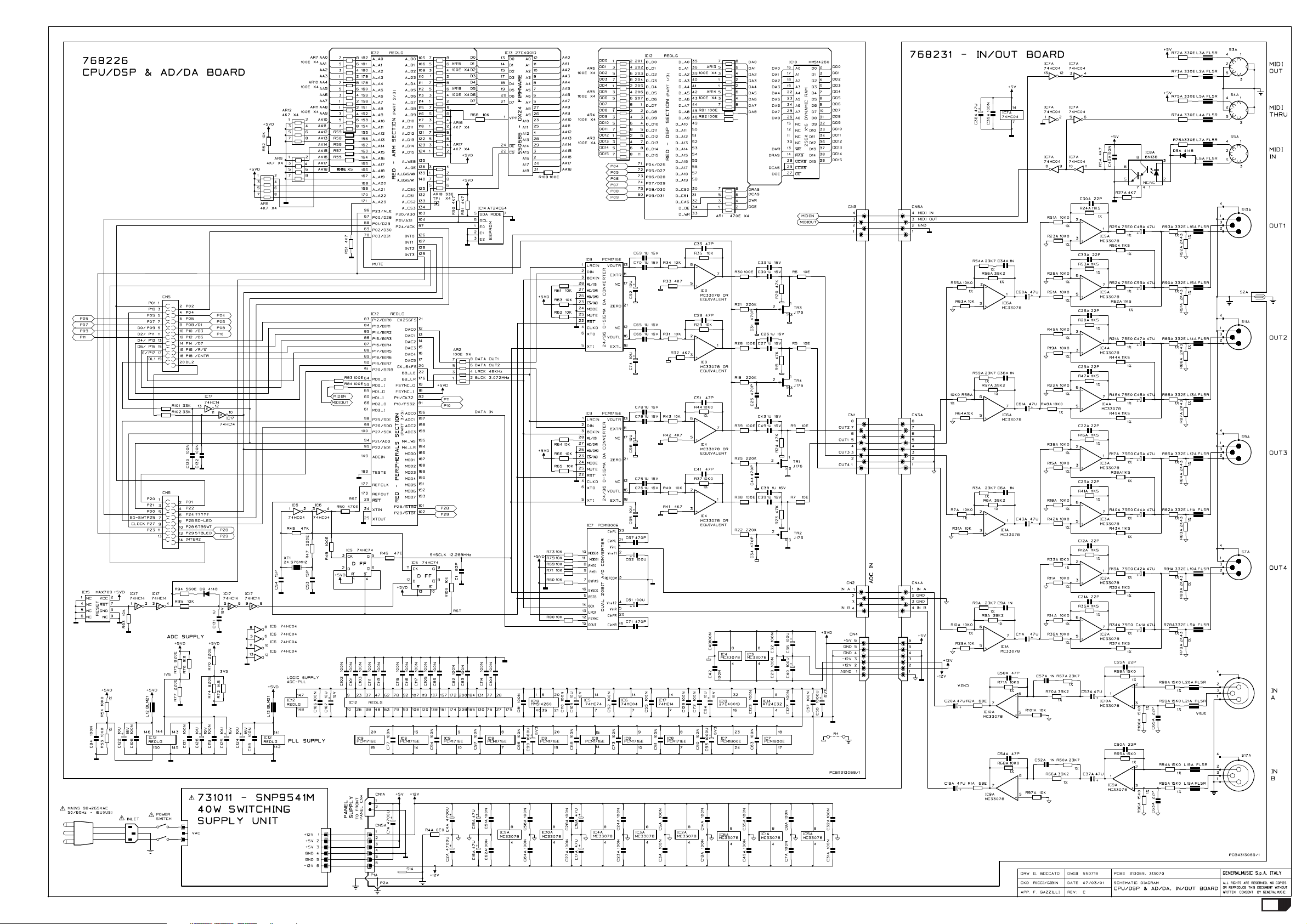
731011731011
731011731011
731011 SNP9541M 40W Switching Supply UnitSNP9541M 40W Switching Supply Unit
SNP9541M 40W Switching Supply UnitSNP9541M 40W Switching Supply Unit
SNP9541M 40W Switching Supply Unit
Controls Panel AssemblyControls Panel Assembly
Controls Panel AssemblyControls Panel Assembly
Controls Panel Assembly
768245768245
768245768245
768245 2x16 Characters Lcd Module2x16 Characters Lcd Module
2x16 Characters Lcd Module2x16 Characters Lcd Module
2x16 Characters Lcd Module
140860 * 14 Contacts Vert Male Dual In Line Strip
080757 * WM-C1602N-2GLYC Wintek 2x16 Characters Lcd Display
768244768244
768244768244
768244 Led & Meters Board (Pcb#313074)Led & Meters Board (Pcb#313074)
Led & Meters Board (Pcb#313074)Led & Meters Board (Pcb#313074)
Led & Meters Board (Pcb#313074)
140874 * Single In Line Vert Male Strip (specify contacts)
103028 * 74HC4094M1R SOIC 8bit Shift/Latch Register
081702 * Led Smd Yellow
081701 * Led Smd Green
081700 * Led Smd Red
054037 * 1K2 1/10w 5% Smd Resistor 0805
054012 * 10E 1/10w 5% Smd Resistor 0805
011060 * 100n 50V 10% Cer. Cap. Smd CL2 Y5V 0805
768243768243
768243768243
768243 Controls Panel Board (Pcb#313073)Controls Panel Board (Pcb#313073)
Controls Panel Board (Pcb#313073)Controls Panel Board (Pcb#313073)
Controls Panel Board (Pcb#313073)
841268 * 14 Wires 15cm Latch/Transition Flat Cable
340856 * 6,4mm Led Spacer
141018 * 20 Contacts Vert Female Connector
141015 * 14 Contacts Vert Female Connector
140918 * 2 Contacts Hor Male Connector
140529 * Microswitch 12V 50mA 0.25mm
110261 * Dial Encoder with 30 Snap H=15mm Alps
103032 * 74HC165D SOIC 8bit P To S Shift Register
103028 * 74HC4094M1R SOIC 8bit Shift/Latch Register
103010 * 74HC04D SOIC Hex Inverter
103000 * 74HC14D Soic Hex Inverter Schmitt Trigger
081000 * PMLL4148 Smd 100mA 75V Signal Diode
080705 * 3mm 60deg Diffused Red Led
055101 * 4K7 X4 1/16w 5% Smd Resistor Array
054060 * 100K 1/10w 5% Smd Resistor 0805
054048 * 10K 1/10w 5% Smd Resistor 0805
054045 * 5K6 1/10w 5% Smd Resistor 0805
054043 * 3K9 1/10w 5% Smd Resistor 0805
054037 * 1K2 1/10w 5% Smd Resistor 0805
054036 * 1K 1/10w 5% Smd Resistor 0805
040091 * 4E7 1/2W 5% Resistor
030565 * 220u 25V 20% Vert Electrolytic Capacitor
030246 * 10u 25V 20% Low Prof Vert Electrolytic Capacitor
011060 * 100n 50V 10% Cer. Cap. Smd CL2 Y5V 0805
011048 * 10n 50V 10% Cer. Cap. Smd CL2 X7R 0805
011020 * 47p 50V 10% Cer. Cap. Smd CL2 X7R 0805
347394 Rubber Switch Actuator
120579 M2 Nut
120021 M2x6tc Screw
Cpu/Dsp & AD/DA BoardCpu/Dsp & AD/DA Board
Cpu/Dsp & AD/DA BoardCpu/Dsp & AD/DA Board
Cpu/Dsp & AD/DA Board
768226768226
768226768226
768226 Cpu/Dsp & AD/DA Board (Pcb#313069)Cpu/Dsp & AD/DA Board (Pcb#313069)
Cpu/Dsp & AD/DA Board (Pcb#313069)Cpu/Dsp & AD/DA Board (Pcb#313069)
Cpu/Dsp & AD/DA Board (Pcb#313069)
550686 * 27C4001D Eprom 4mbit “DX24 Firmware”
250524 * 25x25mm Thermoconductor Adhesive
231000 * BLM21A102STP Smd EMI Coil For Signal
177690 * Heatsink
171039 * Ground Leaf
141018 * 20 Contacts Vert Female Connector
141015 * 14 Contacts Vert Female Connector
141012 * 8 Contacts Vert Female Connector
141010 * 4 Contacts Vert Female Connector
140908 * 6 Contacts Vert Male Small Connector
140606 * DIL32 Socket
130175 * AWG18 Green Cable
120276 * B2.9x6.5mm Screw
106003 * MAX709 Power Monitor With Reset
106001 * MC33078P SOIC Dual Low Noise Op. Amp.
105008 * RED208 Risc Cpu and Dsp
104052 * AT24C64 64Kbit Serial Access EEProm
104003 * HM514260JP SOJ 4Mbit Dynamic Ram Ta=70ns
103043 * PCM1716 24 Bit Stereo Dac
103042 * PCM1800 20 Bit Stereo Adc
103010 * 74HC04D SOIC Hex Inverter
103007 * 74HC74D SOIC Dual Flip-Flop
103000 * 74HC14D Soic Hex Inverter Schmitt Trigger
090856 * J176 TO92 P-Channel J-Fet Transistor
081000 * PMLL4148 Smd 100mA 75V Signal Diode
055103 * 470E X4 1/16w 5% Smd Resistor Array
055102 * 33E X4 1/16w 5% Smd Resistor Array
055101 * 4K7 X4 1/16w 5% Smd Resistor Array
055100 * 100E X4 1/16w 5% Smd Resistor Array
054064 * 220K 1/10w 5% Smd Resistor 0805
054056 * 47K 1/10w 5% Smd Resistor 0805
054054 * 33K 1/10w 5% Smd Resistor 0805
054048 * 10K 1/10w 5% Smd Resistor 0805
054044 * 4K7 1/10w 5% Smd Resistor 0805
054039 * 1K8 1/10w 5% Smd Resistor 0805
054038 * 1K5 1/10w 5% Smd Resistor 0805
054035 * 820E 1/10w 5% Smd Resistor 0805
054033 * 560E 1/10w 5% Smd Resistor 0805
054032 * 470E 1/10w 5% Smd Resistor 0805
054028 * 220E 1/10w 5% Smd Resistor 0805
054024 * 100E 1/10w 5% Smd Resistor 0805
054020 * 47E 1/10w 5% Smd Resistor 0805
054012 * 10E 1/10w 5% Smd Resistor 0805
042605 * 10K0 1/4W 1% Metalized Film Resistor
042260 * 0E 1/4W Resistor
031007 * 10u 16V 20% Smd Electrolytic Tantalium Capacitor
030715 * 1000u 6v3 20% Vert Electrolytic Capacitor
030485 * 100u 25V 20% Vert Electrolytic Capacitor
011103 * 1u 16V 10% Cer. Cap. Smd CL2 XTR 1206
011060 * 100n 50V 10% Cer. Cap. Smd CL2 Y5V 0805
011032 * 470p 50V 10% Cer. Cap. Smd CL2 X7R 0805
011020 * 47p 50V 10% Cer. Cap. Smd CL2 X7R 0805
011014 * 15p 50V 10% Cer. Cap. Smd CL2 X7R 0805
010722 * 24.576MHz Quartz Resonator
In/Out BoardIn/Out Board
In/Out BoardIn/Out Board
In/Out Board
768231768231
768231768231
768231 In/Out Board (Pcb#313070)In/Out Board (Pcb#313070)
In/Out Board (Pcb#313070)In/Out Board (Pcb#313070)
In/Out Board (Pcb#313070)
230569 * FL5R200PNT EMI Coil For Signal
141187 * Hor Female XLR Socket (NC3FAH Neutrik)
141186 * Hor Male XLR Socket (NC3MAH Neutrik)
141102 * 6 Contacts Vert Male Connector
141012 * 8 Contacts Vert Female Connector
141010 * 4 Contacts Vert Female Connector
140918 * 2 Contacts Hor Male Connector
140908 * 6 Contacts Vert Male Small Connector
140212 * 5 Poles Din Horizontal Female Socket
120857 * 6.3mm Vertical Male Faston for Pcb
100919 * MC33078 Dual LN Operational Amplifier
100602 * 74HC04 Hex Inverter
100035 * 6N138 Optocoupler
080103 * 1N4148 100mA 75V Signal Diode
052048 * 10K 1/8w 5% Resistor
052044 * 4K7 1/8w 5% Resistor
052028 * 220E 1/8w 5% Resistor
052022 * 68E 1/8w 5% Resistor
042672 * 39K2 1/4W 1% Metalized Film Resistor
042632 * 18K2 1/4W 1% Metalized Film Resistor
042625 * 15K0 1/4W 1% Metalized Film Resistor
042611 * 11K5 1/4W 1% Metalized Film Resistor
042605 * 10K0 1/4W 1% Metalized Film Resistor
042524 * 2K43 1/4W 1% Metalized Film Resistor
042425 * 332E 1/4W 1% Metalized Film Resistor
042345 * 75E0 1/4W 1% Metalized Film Resistor
030858 * 4700uF 25V 20% Vert Electrolytic Capacitor
030403 * 47u 25V 20% Vert Electrolytic Capacitor
022002 * 1n5 2.5% 100V MKP Polypropylene Capacitor
010595 * 100n 50V -20+80% Ceramic Cap. Multilayer
010304 * 47p 50V 10% CL2 Ceramic Capacitor
010271 * 22p 50V 10% CL2 Ceramic Capacitor
Wiring ConnectionsWiring Connections
Wiring ConnectionsWiring Connections
Wiring Connections
841271 27.5cm Yel/Grn Eye/Faston/Faston Wire with 10E Res
841270 Single 12.5cm AWG18 White Faston/Faston Wire
841269 2 Wires 40cm Faston/Crimp Terminal Cable
841264 6 AWG18 Wires 10cm Crimp Terminal Cable
841263 8 Wires 3cm Flat Cable
841252 6 Wires 12.5cm Crimp Terminal Cable
841206 4 Wires 20cm Flat Cable
841005 7.5cm Yel/Grn Faston/Faston AWG18 Wire
840838 20 Wires 15cm Flat Cable
840826 14 Wires 15cm Flat Cable
840799 4 Wires 7.5cm Flat Cable
840776 2 Wires 25cm Crimp Terminal Cable
Note:Note:
Note:Note:
Note:
- All dimensions are in mm unless otherwise specified.
- The screw description is defined as follows:
type of screw + diameter + X + length + type of head
where type of screw is one of these:
M = Metric thread
B = Self-tapping screw for metal
WL = Self-tapping screw for wood
and type of head is one of these:
tc = cylinder Phillips head
ts = flared Phillips head
tt = rounded Phillips head
te = hexagonal nut head
tsp = flat flared Phillips head
tce = cylinder Allen hexagonal head
tspe = flat flared Allen hexagonal head
- The washer description is defined as follow:
hole diameter + X + external diameter + X + thick
- Each spare part is single quantity unless otherwise specified.
- Asterisk prefix explanation:
Omitted = First level spare part.
One asterisk = Second level, part of previous listed first level part.
Two asterisk = Third level, part of previous listed second level part.
Three asterisk = ............
- Any request for not above mentioned part must encompass specific description including:
1) Model name,
2) Section name,
3) Module code,
4) Reference name,
5) Quantity number.