LEM EQ152 User manual


IMPORTANT SAFETY INSTRUCTIONS
INSTRUCTIONS PERTAINING TO A RISK OF FIRE, ELECTRIC SHOCK OR INJURY TO PERSONS
WARNING - When using electric products, basic precautions should always be followed, including the
following:
1. Read all the SAFETY INSTRUCTIONS before using the product.
2. To reduce the risk of injury, close supervision is necessary when the product is used near children.
3. Do not use this product near water - for example, near a bathtub, washbowl, kitchen sink, in a wet basement
or near a swimming poor or the like.
4. This product in combination with headphones or an amplifier, may be capable of producing sound levels
that could cause permanent hearing loss. Do not operate for a long period of time at high volume level or at
a level that is uncomfortable. If you experience any hearing loss or ringing in the ears, you should consult
an audiologist.
5. This product should be located so that its location or position does not interfere with its proper ventilation.
6. This product should be located away from heat sources such as radiators, heat registers or other products
that produce heat.
7. The product should be connected to a power supply only of the type described on the operating instructions
or as marked on the product.
8. This product may be equipped with a polarized line plug (one blade wider than the other). This is a safety
feature. If you are unable to insert the plug into the outlet, contact an electrician to replace your obsolete
outlet. Do not defeat the safety purpose of the plug.
9. The power-supply cord of the product should be unplugged from the outlet when left unused for a long
period of time. When unplugging the power-supply cord, do not pull on the cord, but grasp it by the plug.
10. Care should be taken so that object do not fall and liquid are not spilled into the enclosure through
openings.
11. The product should be serviced by qualified service personnel when:
A. The power-supply cord or the plug has been damaged; or
B. Objects have fallen, or liquid has been spilled into the product; or
C. The product has been exposed to rain; or
D. The product does not appear to operate normally or exhibits a marked change in performance; or
E. The product has been dropped or the enclosure damaged.
12. Do not attempt to service the product beyond that described in the user-maintenance instructions. All
other servicing should be referred to qualified service personnel.
13. WARNING - Do not place objects on the product's power cord or place it in a position where anyone
could trip over, walk on or roll anything over it. Do not allow the product to rest on or to be installed over
power cords of any type. Improper installations of this type create the possibility of fire hazard and/or personal
injury.
SAVE THESE INSTRUCTIONS
The lightning flash with arrowhead symbol within an equilateral
triangle is intended to alert the user to the presence of uninsulated
"dangerous voltage" within the product's enclosure, that may be of
sufficient magnitude to constitute a risk of electric shock to persons.
The exclamation point within an equilateral triangle is intended to
alert the user to the presence of important operating and
maintenance (servicing) instructions in the literature accompanying
the appliance.

1
Indice
Avvertenze e Installazione............................................................................ 2
Primi Passi...................................................................................................... 3
Pannello Frontale........................................................................................... 4
Power...............................................................................................................5
Controlli di livello dei filtri ................................................................................. 5
Range ..............................................................................................................5
Bypass .............................................................................................................5
Clip................................................................................................................... 5
Selettore di frequenza Lo-Cut..........................................................................5
Selettore di frequenza Hi-Cut ..........................................................................5
Level ................................................................................................................5
Pannello Posteriore....................................................................................... 6
Cavo di alimentazione ..................................................................................... 7
Portafusibile ..................................................................................................... 7
Ground.............................................................................................................7
Connettori Input / Output.............................................................................. 7
Esempi di Collegamento............................................................................... 8
Cavi di Collegamento .................................................................................. 10
Specifiche Tecniche .................................................................................... 12
Indice

2
Collegamento alla rete
L’apparato è dotato di un proprio alimentatore interno. Prima di accenderlo, assicuratevi che la tensio-
ne di rete corrisponda a quella indicata sul retro dell’apparato (è accettata una tolleranza fino a ±10%).
Prima di collegare o scollegare il cavo di alimentazione accertatevi che il pulsante di accensione sia in
posizione OFF (spento).
Accensione e spegnimento
ATTENZIONE: al momento dell’accensione o dello spegnimento accertatevi che gli amplificatori del-
l’impianto audio siano spenti: in questo modo eviterete fastidiosi e talvolta dannosi picchi di segnale.
Collegamento e prevenzione o individuazione di disturbi
Verificate, innanzitutto, che il luogo di installazione non presenti disturbi industriali o a radio frequen-
za. Evitate comunque di installare la vostra apparecchiatura in stretta prossimità di apparecchi radio, TV,
telefoni cellulari, etc., in quanto questi potrebbero causare interferenze rumorose.
Collegando gli altri apparati del vostro impianto audio, ponete molta attenzione ai cosiddetti “loop di
massa” che potrebbero causare ronzii o interferire con le ottime prestazioni di rapporto Segnale/Rumore e di
bassa distorsione del prodotto.
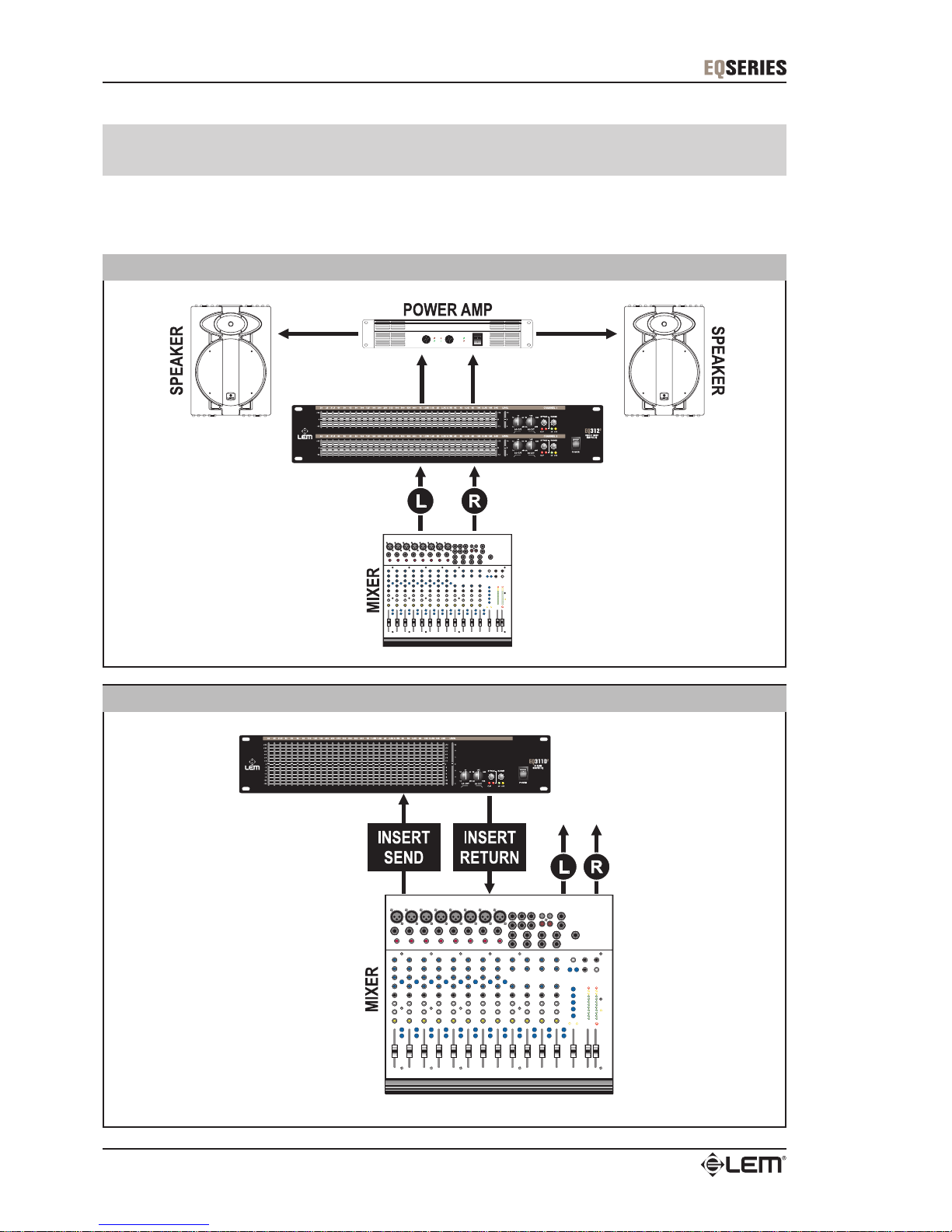
Il metodo migliore (anche se non sempre praticabile) per prevenire loop di massa consiste nel colle-
gare le masse elettriche di tutti gli apparati ad un solo punto centrale (sistema “a stella”). Nel nostro caso,
questo punto centrale può essere considerato proprio il mixer.
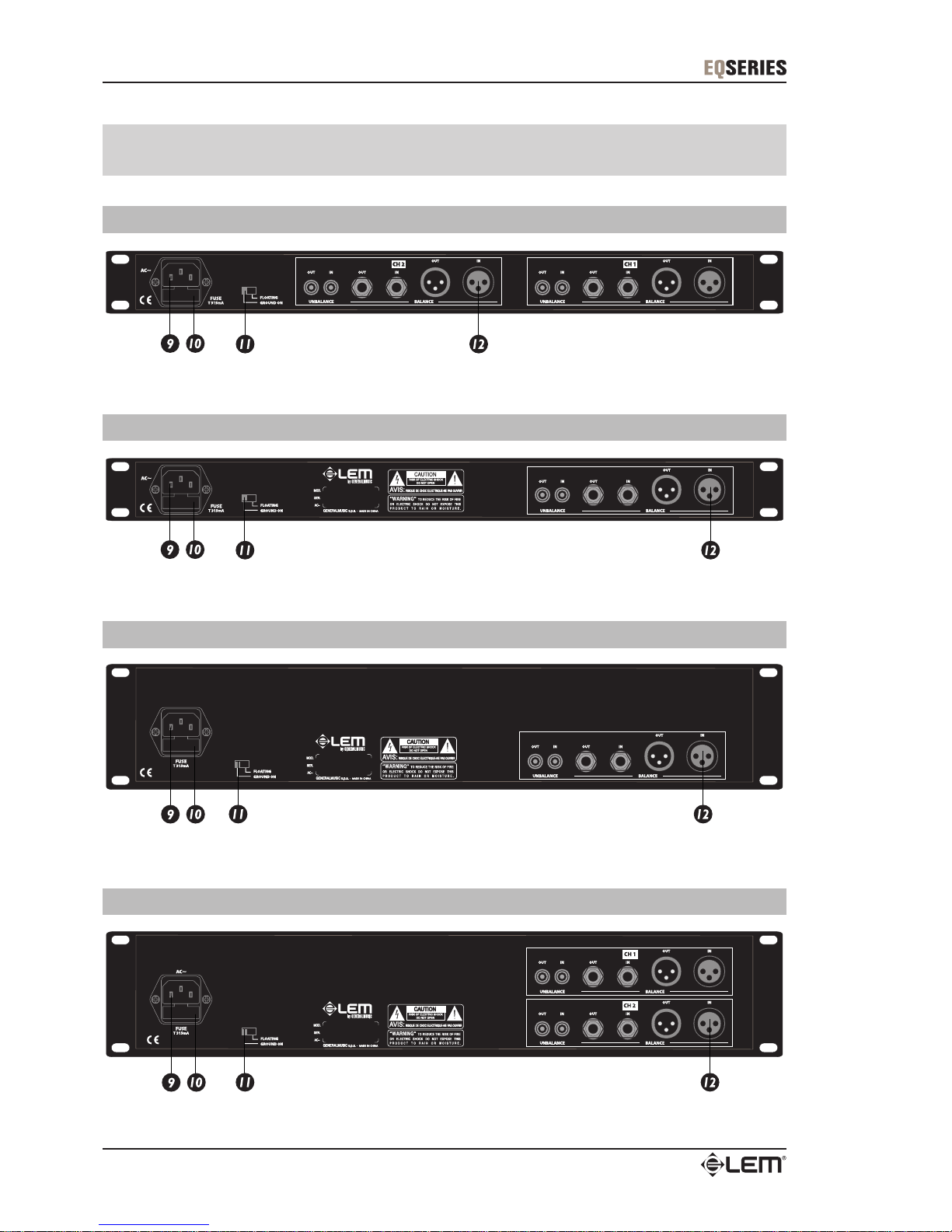
L’equalizzatore grafico, in ogni caso, è dotato del selettore Ground, posto sul pannello posteriore.
Separando la massa elettrica dalla massa telaio, questo selettore vi aiuterà a prevenire e risolvere eventuali
problemi di rumore di fondo e di ronzii.
Provate diverse combinazioni con le altre unità dell’impianto che sono dotate di selettore Ground.
ATTENZIONE: quando agite su questo selettore accertatevi che gli amplificatori dell’impianto audio
siano spenti o siano impostati con volumi ridotti.
Protezione e manutenzione
Non forzate manopole, interruttori e cursori: sono studiati per rispondere ad una leggera pressione e
potrebbero essere danneggiati se usati con forza eccessiva.
Abbiate cura dei cavi di collegamento, fonti di frequentissimi piccoli-grandi guai. Afferrateli sempre per
i connettori, evitate di tirarli con forza ed avvolgeteli evitando nodi o forti torsioni: ne allungherete la vita e
l’affidabilità, a vostro assoluto vantaggio.
Evitate di esporre l’apparato alla irradiazione solare diretta, a forti fonti di calore, ad intense vibrazioni,
ad ambienti molto polverosi o particolarmente umidi o, peggio ancora, alla pioggia: eviterete possibili mal-
funzionamenti, deterioramenti o addirittura shock elettrici ed incendi.
L’apparato è realizzato in materiale antiurto. In ogni caso, proteggetene il trasporto con flight-case per
prevenirne gli incidenti del caso.
A fine uso è sempre consigliabile proteggere l’apparato dalla polvere. In ogni caso, l’eventuale depo-
sito di polvere può essere rimosso usando “a secco” un panno morbido o un pennello.
Non usate mai alcool, acetone o solventi vari.
L’apparato non ha bisogno di ulteriori manutenzioni.
In caso di avaria
Tutte le regolazioni sono esterne ed accessibili alla vostra portata. In caso di avaria non aprite l’appa-
rato, ma rivolgetevi al più vicino Centro di Assistenza Generalmusic/Lem.
Conservazione della documentazione
Conservate questo manuale d’uso per eventuali future consultazioni. Ricordate, inoltre, che sul mer-
cato dell’usato un prodotto ottiene sempre una migliore valutazione se, oltre ad essere ben conservato, è
corredato dalla documentazione e dell’imballo originali.
Avvertenze e Installazione

3
Prima di iniziare ad equalizzare il vostro sistema audio, vi sono alcune informazioni che dovete conoscere e
procedure che dovete seguire.
Ciascun canale dell’equalizzatore grafico possiede tre connettori di ingresso collegati in parallelo e tre con-
nettori d’uscita collegati in parallelo.
Prima di collegare il vostro equalizzatore ad altri apparati, consultate il capitolo “Cavi di Collegamento” e
verificate le specifiche di cablaggio.
Non collegate i microfoni direttamente all’equalizzatore, in quanto i microfoni richiedono una pre-amplifica-
zione.
Ciascun canale di ogni modello è dotato di un pulsante Bypass con relativo indicatore a LED.
Quando il Bypass è attivato (LED acceso) tutte le regolazioni di equalizzazione vengono ignorate e il segna-
le passa attraverso l’apparato senza subire alcuna modifica.
Il selettore Range vi consente di impostare la quantità di esaltazione/attenuazione dei controlli di filtraggio.
Verificate se sia impostato a ±6dB (LED verde) o a ±12dB (LED giallo).
Il potenziometro Level agisce congiuntamente al selettore Range, funzionando da controllo generale con
valori compresi tra 0 (chiuso) e 10.
Il LED rosso Clip si accende quando il segnale raggiunge 5dB al di sotto del punto di clipping.
Per ottenere un buon rapporto segnale/rumore, il livello deve essere mantenuto abbastanza alto, ma evitan-
do che il LED Clip si accenda in modo persistente. Se il LED Clip si accende permanentemente dovete
abbassare il livello generale attraverso il controllo Level.
Di seguito sono elencati alcuni suggerimenti per il setup iniziale.
1. Posizionate il Level del canale sulla posizione 10.
2. Attivate il modo Bypass (LED acceso).
3. Regolate tutti gli sliders dei controlli di frequenza sulla posizione 0dB (scatto centrale).
4. Impostate il valore Range a ±6dB (LED verde acceso).
5. Immettete del segnale nel sistema audio.
6. Disattivate il modo Bypass (LED spento).
7. Se il LED Clip si accende abbassate il livello generale.
8. Potete iniziare ad equalizzare.
9. Se non ottenete un livello in uscita sufficientemente alto, impostate il valore Range a ±12dB
(LED giallo acceso).
10. Se il LED Clip si accende permanentemente, abbassate il livello generale.
Primi Passi
Primi passi

4
Pannello Frontale
EQ 152 - Dual 15 Band Graphic Equalizer
EQ 311 - 31 Band Graphic Equalizer
EQ 311D - Long Throw 31 Band Graphic Equalizer
EQ 312 - Dual 31 Band Graphic Equalizer
Pannello frontale

5
Power
Premete questo pulsante per accendere e spegnere l’equalizzatore grafico.
ATTENZIONE: accertatevi sempre che gli amplificatori dell’impianto audio siano spenti.
Controlli di livello dei filtri
Questi sliders controllano il livello d’uscita di ciascun filtro passa-banda:
modelli a 31 bande 1/3 ottava da 20Hz a 20kHz
modello a 15 bande 2/3 ottava da 25Hz a 16kHz
Tutti i modelli sono dotati di filtri FIR e di circuitazione a Q costante (campana costante) con precisio-
ne del 3% sulla frequenza centrale.
La posizione centrale (in corrispondenza dello scatto) garantisce una risposta piatta.
Range
Questo controllo imposta la quantità di esaltazione/attenuazione di tutti i controlli di filtraggio:
± 6dB = LED verde
±12dB = LED giallo
Bypass
Questo controllo attiva e disattiva il modo Bypass.
In Bypass (LED rosso acceso) il segnale viene inviato direttamente dall’ingresso all’uscita senza
passare attraverso alcun circuito (“bypass fisico”).
Usate questa funzione per comparare segnale equalizzato e non-equalizzato, oppure per saltare la
sezione EQ.
Clip
Questo LED rosso si accende se il segnale di qualsiasi sezione dell’equalizzatore raggiunge i 5dB
prima della saturazione.
Un’accensione occasionale è accettabile. In caso di accensione persistente, se volete evitare distor-
sioni udibili, dovete abbassare i controlli di livello dell’equalizzatore e/o abbassare il livello d’uscita
dell’apparato che precede l’equalizzatore nella catena audio.
Lo-Cut
(solo modelli a 31 bande)
Questo controllo determina la frequenza di taglio del filtro passa-alte (HPF) dell’equalizzatore.
Agendo su questo potenziometro potete impostare la frequenza di taglio tra 10Hz e 250Hz.
Grazie alla alta pendenza del filtro, Lo-Cut può essere efficacemente utilizzato per “tagliare” il rumore
di fondo dell’apparato che precede l’equalizzatore nella catena audio o per prevenire la risonanza in
bassa frequenza tipica dei sistemi di amplificazione installati in ambienti ristretti, palchi, etc.
Hi-Cut
(solo modelli a 31 bande)
Questo controllo determina la frequenza di taglio del filtro passa-basse (LPF) dell’equalizzatore.
Agendo su questo potenziometro potete impostare la frequenza di taglio tra 3kHz e 50kHz.
Grazie alla alta pendenza del filtro, Hi-Cut può essere efficacemente utilizzato per “tagliare” il rumore
in alta frequenza dell’apparato che precede l’equalizzatore nella catena audio o per ridurre l’eccesso
di frequenze alte ed ottenere un suono più naturale in performances acustiche.
Level
Questo potenziometro controlla il livello del segnale in ingresso all’equalizzatore grafico.
Lo scatto centrale indica la posizione di parità di guadagno (livello inalterato).
Agite su questo controllo per ridurre gli eccessi di segnale (LED clip acceso).
Pannello frontale

6
Pannello Posteriore
EQ 152 - Dual 15 Band Graphic Equalizer
EQ 311 - 31 Band Graphic Equalizer
EQ 311D - Long Throw 31 Band Graphic Equalizer
EQ 312 - Dual 31 Band Graphic Equalizer
Pannello posteriore

7
Presa per cavo di alimentazione
Portafusibile
In caso di sostituzione, assicuratevi di usare sempre lo stesso tipo di fusibile.
Qualora i fusibili dovessero bruciarsi continuamente, interrompete le sostituzioni e rivolgetevi ad un
centro di assistenza qualificato.
Ground
Questo selettore consente di separare la massa elettrica dalla massa del telaio dell’equalizzatore.
In caso di problemi di rumore di fondo e di ronzii agite provate ad agire sul selettore, accertandovi che
gli amplificatori dell’impianto audio siano spenti o siano impostati con volumi ridotti.
Connettori Input / Output
3 connettori di ingresso collegati in parallelo:
XLR-F (bilanciato), JACK (bilanciato), RCA Phono (sbilanciato).
ATTENZIONE: può essere usato un solo connettore alla volta.
3 connettori di uscita collegati in parallelo:
XLR-M (bilanciato), JACK (bilanciato), RCA Phono (sbilanciato).
ATTENZIONE: può essere usato un solo connettore alla volta.
Pannello posteriore

8
Gli equalizzatori grafici possono essere usati ovunque sia necessario modificare la definizione timbrica di un
sistama sonoro. Un equalizzatore grafico è una soluzione per molti problemi audio e per molte applicazioni
creative.
Esempi di Collegamento
Sistema di amplificazione stereo
Equalizzazione attraverso mandata/ritorno insert di un mixer
Esempi di collegamento

9
Equalizzazione di uno strumento musicale
Equalizzazione di un sistema audio per chitarra o basso
Esempi di collegamento

10
In questo capitolo sono riportati gli schemi di connessione dei connettori utilizzabili.
Abbiate cura dei cavi di collegamento, fonte di frequentissimi piccoli-grandi guai. Afferrateli sempre
per i connettori, evitate di tirarli con forza ed avvolgeteli evitando nodi o forti torsioni: ne allungherete la vita
e l’affidabilità, a vostro assoluto vantaggio.
Prima di utilizzarli verificate che le connessioni siano realizzate nel modo corretto e che tutti i contatti
siano in perfetta efficienza e privi di tracce di ossidazione: molti inconvenienti, come falsi contatti, rumori di
massa, scariche, etc. sono spesso dovuti unicamente all'utilizzo di cavi inadatti, logorati o danneggiati.
XLR-M bilanciato
XLR-F bilanciato
Cavi di Collegamento
JACK bilanciato
Cavi di collegamento

11
Raccordo sbilanciato XLR-M - JACK
Raccordo sbilanciato XLR-F - JACK
RCA phono sbilanciato
Cavi di collegamento

12
Specifiche Tecniche
Specifiche tecniche
Modello EQ 152 EQ 311 EQ 311D EQ 312
BANDE
2 x 15
2/3 Ottava
20Hz - 16kHz
1 x 31
1/3 Ottava
20Hz - 20kHz
1 x 31
1/3 Ottava
20Hz - 20kHz
2 x 31
1/3 Ottava
20Hz - 20kHz
TIPO
PRECISIONE
CORSA 20mm
scatto centrale
20mm
scatto centrale
60mm
scatto centrale
20mm
scatto centrale
INTERVENTO
CONNETTORI
IMPEDENZA
LIVELLO MASSIMO
CONNETTORI
IMPEDENZA
LIVELLO MASSIMO
BYPASS PASSIVO
SOGLIA del LED CLIP
FILTRO LO-CUT
FILTRO HI-CUT
RISPOSTA IN FREQUENZA
T.H.E. + NOISE
RAPPORTO SEGNALE/RUMORE
ALIMENTAZIONE
DIMENSIONI (LxAxP) mm 480 x 44 x 220 480 x 44 x 220 480 x 88 x 220 480 x 88 x 220
PESO 3.14 k
g
3.08 k
g
3.70 k
g
4.08 k
g
GENERALI
+18dBv
XLR-M (bilanciati), 1/4" JACK (bilanciati), RCA phono (silanciati)
XLR-F (bilanciati), 1/4" JACK (bilanciati), RCA phono (silanciati)
Q Costante
3% sulla frequenza centrale
±6dB o ±12dB (selezionabile)
20kOhms bilanciato; 15kOhms sbilanciato
INGRESSI
USCITE
SI
5dB prima del Clippin
g
10-250Hz, 12dB/Ott
Tip. <150 Ohms
vedere etichetta sull'apparato
0.02% @1kHz
-93dB @ 1kHz
3k-50kHz, 12dB/Ott
20-20kHz, -3dB
+16dBv

1
Contents
Warnings and Installation............................................................................. 2
Getting Started............................................................................................... 3
Front Panel ..................................................................................................... 4
Power Switch ................................................................................................... 5
Filter Level Controls......................................................................................... 5
Filter Range Switch & Indicators .....................................................................5
Bypass Switch & Indicator...............................................................................5
Clip Indicator.................................................................................................... 5
Lo-Cut Frequency Control ...............................................................................5
Hi-Cut Frequency Control................................................................................5
Level Control....................................................................................................5
Rear Panel ...................................................................................................... 6
Power Cord...................................................................................................... 7
Fuse Holder .....................................................................................................7
Ground- Lift Switch ..........................................................................................7
Input / Output Connectors ...............................................................................7
Connection Examples ................................................................................... 8
Connection Cables ...................................................................................... 10
Technical Specifications............................................................................. 12
Contents

2
Connection to the mains supply
The Graphic Equalizer has its own built-in power supply. Before switching on the unit, make certain
that the mains voltage matches that shown on the rear (a tolerance of up to ±10% is acceptable).
Before connecting or disconnecting the power cord, make certain the ON/OFF switch is in the OFF
position OFF.
Switching on and off
CAUTION: before switching on or off, make certain the sound system’s amplifiers are off: this will
avoid signal peaks, which are annoying and sometimes dangerous (particularly for speaker enclosures).
Connecting and preventing or identifying interference
First of all, check that the apparatus is installed in a place free from industrial or RF (radio frequency)
interference. Avoid installing your equipment very near radio or TV sets, mobile phones, etc., as these can
cause noisy interference.
When connecting the other parts of your sound system, watch out for the so-called “ground loops”,
which could cause hum and jeopardize the products’s excellent Sound-to-Noise and low distortion charac-
teristics.
The best way (even if not always feasible) to avoid ground loops is to connect the electric ground of all
the equipment to a single central point (“star” system). In this case, the central point can be the mixer.
The graphic equalizer, anyway, is equipped with a rear panel Ground Lift, which will help you to avoid
or solve hum and buzzing troubles.
CAUTION: before changing your grounds around, always turn your amplifiers down.
Try different combinations of lifting grounds on units that are supplied with ground lift switches or
make sure all chassis are connected to earth ground, either through the A.C. power cord ground or by the
front panel rack mount screws.
Protection and maintenance
Don’t force knobs, switches or faders: these are designed and manufactured to respond to light pres-
sure and could be damaged if used with excessive force.
Take care of your connector cables, a very frequent cause of small/big problems. Always grip them by
the connector, avoid pulling them forcefully and wind them without forming knots or sharp bends: they’ll last
longer this way, and be more reliable, which is a definite advantage.
Avoid exposing the product to strong direct sunlight, high temperatures or intense vibrations, in very
dusty or particularly damp surroundings or, even worse, in the rain: this will help to avoid the risk of faulty
operation, deterioration or even shock electric shocks and fires.
The product is built in shock-resistant material. Nevertheless, protect it during transport with a flight-
case to avoid the risk of any casual accidents.
When you’ve finished using the apparatus, it’s always advisable to protect it from dust, but any dust
that does form should be removed using a cloth or a soft brush. Never use alcohol, acetone or any solvents.
The graphic equalizer does not require any other maintenance.
In the event of breakdown
All user-adjustable parts are external and easily accessed.
In the event of a breakdown, do not open the apparatus, but contact the nearest Generalmusic/Lem
Service Centre.
Keeping the documentation
Keep this user’s manual for future consultation. Also remember that the mixer will get a better price on
the secondhand market if (as well as being in good condition) it has its original documentation and packag-
ing.
Warnings and Installation
Warnungs and installation

3
Before starting to equalize your sound system there is some information you should know and procedures
you should follow.
Each Channel of the graphic equalizer has three paralleled input and output connectors.
Please refer to the “Connection Cables” chapter and check the cable wiring specifications before to connect
your equalizer to other units.
Do not directly connect microphones into the equalizers, since microphones require a preamp.
Each channel of all models is equipped with a Bypass switch with LED indicator.
When the Bypass is activated (LED lighted) all equalization settings are ignored and the signal flows through
at unity gain.
The Range switch let you set the cut/boost amount of the filter level controls.
Check if it set as ±6dB (green LED) or as ±12dB (yellow LED).
The Level control potentiometer operates in conjunction to the Range switch, performing as an overall
control between 0 and 10.
The red Clip LED lights up when signal reaches 5dB prior to clipping.
To obtain a good signal/noise ratio, the gain level must be kept quite high, but avoiding that the Clip LED light
up persistently. If the Clip LED is steadily on you must readjust the Level control.
Below are some tips while doing the initial set up.
1. Set channel Levels to 10 on the front panel.
2. Select the Bypass switch (red LED on).
3. All filter slide controls to the center detent or 0dB.
4. Select the ±6dB Range switch (green LED on).
5. Apply signal to the system.
6. Release the Bypass switch (red LED off).
7. If the Clip LED is on you must turn down the level control.
8. You may now start equalizing your system.
9. If you don’t obtain enough output gain, set the Range switch to ±12dB (yellow LED on).
10. If the Clip LED illuminates steadily, turn down the Level control until the LED is off.
Getting Started
Getting started

4
Front Panel
EQ 152 - Dual 15 Band Graphic Equalizer
EQ 311 - 31 Band Graphic Equalizer
EQ 311D - Long Throw 31 Band Graphic Equalizer
EQ 312 - Dual 31 Band Graphic Equalizer
Front panel

5
Power Switch
Press this button to turn the graphic equalizer ON or OFF.
CAUTION: always make certain the sound system’s amplifiers are off.
Filter Level Controls
These sliders control the output level of each band-pass filter:
31 band models 1/3 octave 20Hz to 20kHz
15 band model 2/3 octave 25Hz to 16kHz
All models feature RFI filters and constant Q circuitry with 3% center frequency accuracy.
Center detent position is grounded for guaranteed flat response.
Filter Range Switch & Indicators
This control sets (as a group) the maximum boost/cut capability of the filter sliders as follows:
± 6dB = green LED
±12dB = yellow LED
Bypass Switch & Indicator
This control sets the Bypass mode.
In Bypass mode (red LED on) the signal is routed directly from the input to the output without passing
through any circuit (“hard-wire bypass”).
Use this switch to compare equalized and non-equalized material, or to bypass the EQ section.
Clip Indicator
This red LED illuminates if any section of the equalizer is within 5dB of clipping.
Occasional blinking of this LED is acceptable, but if it remains on more than intermittently you should
turn down either the equalizer’s level controls or reduce the output level of the preceding component
to avoid audible distortion.
Lo-Cut
(31 band models only)
This control determines the roll-off frequency of the High-Pass Filter (HPF) in the instrument.
The roll-off frequency can be adjusted from 10Hz to 250Hz by turning this knob.
Thanks to its high roll-off slope, the HPF can be efficiently used to cut down the “HUM” noise from
preceding instruments or to prevent the low-frequency resonance while the speakers are installed in
an enclosed acoustic environment.
Hi-Cut
(31 band models only)
This control determines the roll-off frequency of the Low-Pass filter (LPF) in the instrument.
The roll-off frequency can be adjusted from 3kHz to 50kHz by turning the knob.
Thanks to its high roll-off slope, this LPF can be effectively used to cut down the high-frequency noise
from preceding instruments, or especially used to roll-off high frequency sound to obtain a more
natural sound in acoustic situations.
Level Control
This knob controls the level of signal coming into the instrument.
Unity gain can be set by turning this knob to its center detent position.
Turn this control down if the Clip LED illuminates steadily (meaning excessive input signal).
Front panel

6
Rear Panel
EQ 152 - Dual 15 Band Graphic Equalizer
EQ 311 - 31 Band Graphic Equalizer
EQ 311D - Long Throw 31 Band Graphic Equalizer
EQ 312 - Dual 31 Band Graphic Equalizer
Rear panel
This manual suits for next models
3
Table of contents
Languages:
Other LEM Recording Equipment manuals