Elk Products ELK-M1XEP User manual

ELK-M1XEP
M1 Ethernet Interface
INSTALLATION
MANUAL
828-397-4200 Voice
828-397-4415 Fax
http://www.elkproducts.com
email: [email protected]
PO Box 100 • Hwy. 70W • Hildebran, NC 28637 • USA
L524 5/19
v2

ELK-M1XEP v2 Installation Manual
Page 2
Table of Contents
If your M1XEP contains rmware older than version 2.0.0 some
functions described in this manual may not be available.
About M1XEP With “New” Version 2 Firmware
Version 2 rmware adds some exciting and noteworthy changes to an
M1XEP Ethernet Interface. An extended list of email service providers are
now supported, including some with SSL/TLS encryption requirements.
This version also supports M1Cloud remote services available through our
M1Cloud partners. In light of the functionality available through ELK's free
M1ToGo software, third-party apps for smart devices, and M1Cloud services,
we have removed the out of date Java based web server user interface from
the Version 2 rmware. For details on email enhancements, see page 9. For
information on remote control options, see page 16.
Features and Specications .......................................................................................................... 3
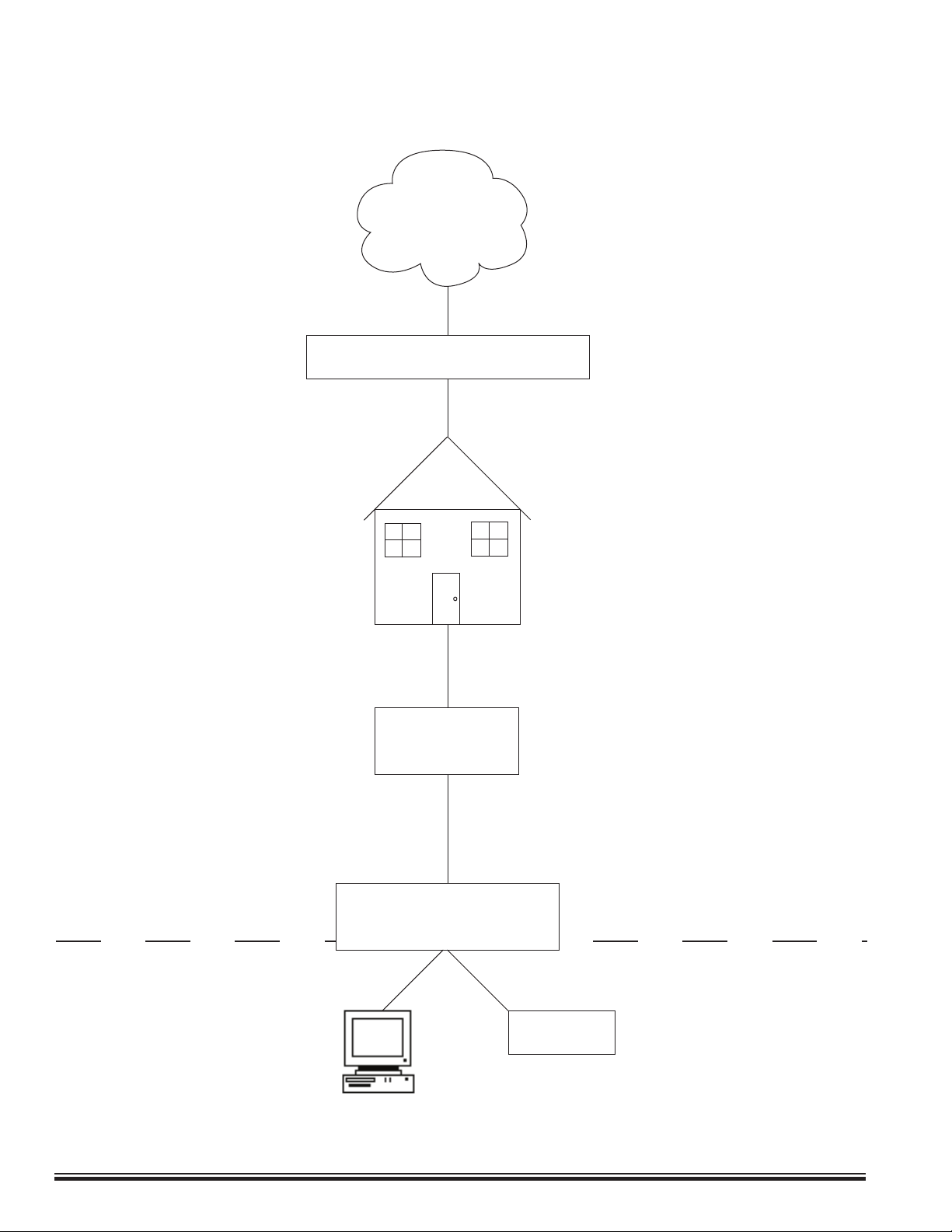
Basics of Networking ..................................................................................................................... 4
Installation and Hookup ................................................................................................................. 5
LED Indicators ................................................................................................................................ 6
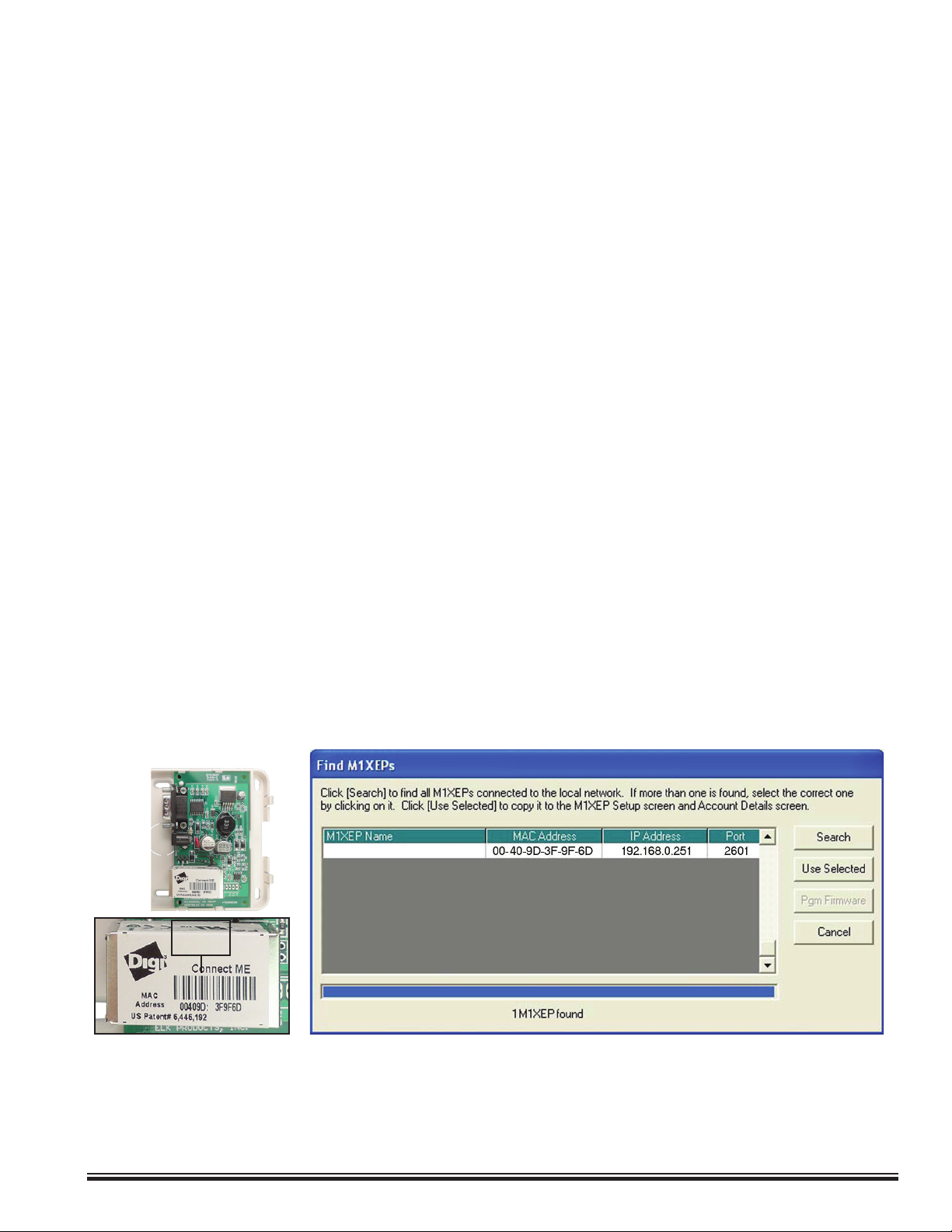
Establishing Initial Connection Over the Local Network ............................................................ 7
Conguring the M1XEP .................................................................................................................. 8
Network Setup -TCP/IP Settings ...................................................................................................... 8
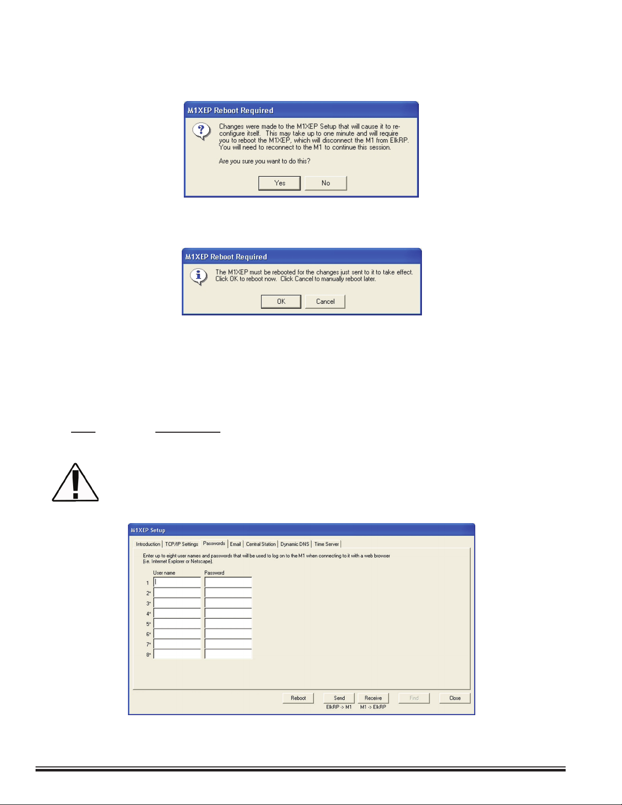
Sending Changes to M1 Ethernet Interface and Save to ElkRP2 ............................................... 10
Setup of User Names & Passwords .............................................................................................. 10
Email Notication Setup .................................................................................................................11
Central Station Setup .................................................................................................................... 12
Dynamic DNS Setup ....................................................................................................................... 14
Time Server Setup .......................................................................................................................... 15
Audio Setup ..................................................................................................................................... 16
Notes on Router Setup ................................................................................................................... 16
Other Ports Used By the M1XEP ................................................................................................... 16
Connecting ElkRP to the Control through the Internet ............................................................. 17
Forcing the DHCP/IP Address Settings to Known Values ........................................................ 18
Updating the Firmware in the M1 Ethernet Interface ................................................................ 18
Remote Control Options .............................................................................................................. 20
Glossary of Terms ........................................................................................................................ 21
Troubleshooting Guide ................................................................................................................ 22

ELK-M1XEP v2 Installation Manual Page 3
FEATURES:
•Secure connection with password protection and SSL/TLS encryption
•Flash Memory for Firmware Updating
• Event notication via E-Mail (SMTP)
•Supports automatic Dynamic DNS Updates with providers using the DynDNS protocol.
•Supports Network Time Protocol for synchronizing the M1/EZ8’s clock with an Internet time server.
•Internet Monitoring and Reporting Capability
•Network stack supporting the following protocols:
TCP,UDP,DHCP,SSL/TLS, NTP, SMTP
•Federal Information Processing Standards (FIPS) 128 bit encryption
•Integrated 802.3 compliant 10/100 Mbit network interface
•RS232, DB9M 9-pin serial port connection
•Connects to the M1 RS-232 Serial port (Port 0). The baud rate for this port must be set to 115,200 (factory default)
•RJ45 8-pin Network Jack
• 2.1mm barrel type power connector (center positive)
•LED Indicators for Power, Link, and Data
SPECIFICATIONS:
•Operating Voltage: 12 Volts D.C. from Elk-P1216 Plug-in Power Supply **
•Current Draw: approx. 300 mA
•Housing Dimensions: 4.25" x 6.375" x 2.125"
•Circuit Board Dimensions: 2.25" x 3.95"
** The M1XEP may be powered from a dierent 12VDC power source. A 2.1 mm barrel type
connector is required for the power connection and the center of the barrel connector
must be positive (+).
Any required network equipment, i.e. Ethernet switch, router, cable modem, etc. including
the plug-in power supply for the M1XEP, MUST be backed up with an adequately sized UPS
(Uninterruptible Power Supply) in order for the equipment to continue operating during
brief power outages.
The non-secure port in the M1XEP is intended for use within the LAN ONLY. Only devices
on the local network (behind the network router) should connect to this port. We strongly
discourage port forwarding the non-secure port outside the LAN.
Features and Specications
APPLICATION:
The ELK-M1XEP is an Ethernet Appliance with a RS-232 Serial Port Interface. It may be used to connect a control in
the M1 Family to an Ethernet network. It features email event notication and FIPS compliant encryption algorithms for
security sensitive environments. It is powered by an ELK-P1216 12 Volts DC, 1.5 Amp plug-in power supply/adapter. A
software setup utility is built into ElkRP for conguring the connection setup, network password, etc. The M1 Ethernet
Interface is factory defaulted to obtain a dynamic IP address from a DHCP server (i.e. router, cable modem, etc.). It may
optionally be setup with a static IP address.

ELK-M1XEP v2 Installation Manual
Page 4
Basics of Networking
WAN
LAN
The installer must have a basic understanding of Ethernet setup to install and congure the M1XEP. If you do not
have this basic knowledge, please seek the assistance of a network professional.
The
Internet
Internet Service Provider (ISP)
Location
Broadband
Modem
Network Router
M1XEP
PC
Technical support from Elk
Products, Inc. is limited to the setup
and connection of the M1 Ethernet
Interface inside the local network.
Connection to outside the local
network may require assistance from
others, including the Internet service
provider and the network administrator.
The broadband modem may need to be bridged
to allow the IP address to be passed to the
router. Contact the manufacturer of the modem
for assistance.
Refer to the Notes on
Router Setup located
on page 14.
Local Area Network
Wide Area Network

ELK-M1XEP v2 Installation Manual Page 5
Installation and Hookup
The following connections are required for the M1XEP Ethernet Interface.
a. The DB9M 9-pin male connector should be connected to the DB9F 9-pin female serial port (port 0) on the
Control using a standard 9-pin male to female serial cable (included). The M1Gold has the main serial port
(port 0) on board, while the M1EZ8 requires the M1EZ8MSI Main Serial Interface to provide the port 0
connection. The M1XEP should be mounted within 10 feet of the Control. The baud rate of the Control's
serial port must be set to 115,200, which is the factory default.
b. The 2.1mm barrel type connector is used to connect an ELK-P1216 Plug-in Power Adapter. The M1 Ethernet
Interface operates from 12 Volts DC and draws approximately 300 mA. The center pin of the barrel connector
is positive.
1. Remove power from the Control before making any connections.
2. Connect the serial port cable from the Control to the M1XEP. Connect a network patch cable from the M1XEP to
the LAN (local area network) switch or router. Power up the Control.
3. Connect the power cable from the P1216 plug-in power supply. Plug the P1216 into a 110V power outlet. The
M1XEP should power up and attempt to link up with the Ethernet network.
4. Enroll the M1 Ethernet Interface into the Control. Using the keypad, access the Installation Programming menu
(Menu 9). Choose Bus Module Enrollment (Menu 1) and press the right arrow key to start the enrollment. When
the enrollment is complete press the ELK or * (Asterisk) key to exit.
Any required network equipment, i.e. Ethernet switch, router, cable modem, etc. including
the plug-in power supply for the M1XEP, MUST be backed up with an adequately sized UPS
(Uninterruptible Power Supply) in order for the equipment to continue operating during brief
power outages.
5. Proceed to Establishing Initial Connection.
The M1XEP does not connect to the RS-485 data bus on the control, therefore it will not appear
in the list of devices enrolled on the keypad. However, the enrollment process is necessary to
ensure proper supervision of the device. If the M1XEP is removed, it must be "un-enrolled" by
completing the Bus Module Enrollment process to prevent an "Ethernet Trouble" from occurring.
ElkRP will display the current rmware, hardware, and bootware versions of the M1XEP on the
"Enroll/Update Control and Devices" screen. This screen is accessed from the Send/Rcv menu
when connected to the control.
c. The RJ45 8-pin network jack is used to connect the M1XEP to a LAN/WAN Ethernet network switch or
router. This requires a standard network 8-pin RJ45 terminated patch cable (not included).
a.
b.
c.

ELK-M1XEP v2 Installation Manual
Page 6
LED Indicators
Power LED Indicator
LED Color Description Normal State
Amber/Orange
Green
Network Link Indicator
Network Trac Indicator
On-Solid
On-Blinking
These LEDs are located in the upper left and right corners of the
RJ-45 connector as shown in the image to the right. During a reboot,
the green light will be o and the orange light will be on for 30-45
seconds. When the reboot is complete, both lights will be o for a
second, and then the orange light will come on solid and the green
light will begin to blink. Wait several seconds before re-establishing a
connection with the control.
RJ-45 Connector LED Indicators
LED Color Description Normal State
Orange DC Power Indicator On-Solid
The power LED indicator is located near the power connector as
shown in the image to right. If this LED does not come on or ashes
when power is connected, check the output of the power source.

ELK-M1XEP v2 Installation Manual Page 7
Establishing Initial Connection Over the Local Network
Finding the M1XEP on the Local Network
Before beginning the M1XEP setup, please ensure that the Control is programmed to transmit
ASCII strings at 115,200 baud for each of its available conditions to allow the M1XEP to provide
access to the information. Using the Keypad Installer Programming, or the ElkRP software,
access the Globals Menu (Menu-07) and program yes for options 35, 36, 37, 38, 39, and 40. Verify
that Option 34 is set to 115,200.
For the initial setup, ElkRP and the M1XEP must be on the same local network. ElkRP cannot "nd" an M1XEP
outside of the local area network. The M1XEP is shipped with DHCP enabled. If a DHCP server exists on your
network the M1XEP will obtain a “dynamic” IP address, gateway address, and subnet mask allowing it to work on the
local network. If not, the factory programmed (default) IP address is 192.168.0.251.
1. Start the ElkRP software and open the desired account.
a. On the account details screen, click the 'M1XEP Setup' button located near the lower right side of the
screen. With the 'Introduction' tab selected, take a few minutes to read this information.
b. When you are ready to proceed, click the 'Find' button. This will open the “Find M1XEPs” screen.
c. ElkRP will search for all M1 Ethernet Interfaces connected to the local network. If the installation and hookup
procedure has been completed correctly, the M1XEP should be listed on this screen. Only one
should be found, unless there are multiple units installed. If you are unable to nd the M1XEP, please
refer to the troubleshooting section of this manual on page 20.
d. Verify that the MAC address in the second column matches the MAC address of the M1XEP. The MAC
address is located on top of the white barcode label on the RJ45 connector of the unit (see image
below).
e. Note the IP address in the third column. This is the address used to connect/communicate with the
M1XEP. Remember, if a DHCP server is on the network and the M1XEP is still set for DHCP (factory
default), this number will most likely be a "dynamic" address. However, in the absence or failure of a DHCP
server, the M1XEP will default to its last static IP address, which is set from the factory to 192.168.0.251.
To force the DHCP/IP address settings to known values, please reference page 18 of this manual.
2. Highlight the M1XEP to be congured and click the 'Use Selected' button. This will copy the IP address and Port
settings to the ElkRP Account Details location. Click CLOSE to exit this screen.

ELK-M1XEP v2 Installation Manual
Page 8
Conguring the M1XEP
Connecting ElkRP2 to the Control Over the Local Network
1. Look at the lower right side of the "Account Details" screen for the two data entry blocks labeled: "System URL/
IP" and "Port". The IP address and port should have been copied from the "Find M1XEPs" screen during the
previous steps. Verify that the values are correct.
2. Make sure that the serial number is correct and the "RP Access Code" is set to the correct value programmed into
the control (default=246801).
3. From the toolbar at the top of the screen, click "Connection", then choose "Network"
4. If everything is setup properly ElkRP2 should now connect to the M1 control through the M1XEP.
Many of the features provided by the M1XEP require newer versions of M1 Control rmware,
M1XEP rmware, and ElkRP software. Current software and rmware updates, as well as release
notes can be downloaded from www.elkproducts.com. Please reference the corresponding
section of this manual for information on which version is required for each feature.
Network Setup - TCP/IP Setting
A router serving DHCP should not need any conguration to allow the M1XEP to connect inside the local network
using a "dynamic" IP address. If desired, the M1XEP can be congured with your choice of a “static” (non-changing)
IP address. For communications outside the local network you will need to establish one or more open ports on the
router. Please refer to Notes on Router Setup on page 16 and the documentation of the router for more details.

ELK-M1XEP v2 Installation Manual Page 9
2. As previously discussed, the M1XEP is factory defaulted to DHCP, which means that it expects to be assigned a
“dynamic” IP address. Be aware that a “dynamic” IP address can periodically change for many reasons, including
a power down/up cycle. You may optionally assign the M1XEP a permanent “static” address, if permitted by the
network. The static IP address MUST NOT be assigned to any other device on the network. Conguring a static
IP address will also involve setting values for subnet mask, default gateway, and primary and secondary DNS
servers. These settings can be obtained from your network administrator or Internet service provider. Valid IP
addresses DO NOT end in 0, 1, 254, or 255. The primary and secondary DNS servers must be entered correctly
in order for many features of the M1XEP (email, ddns, time server, etc.) to work correctly.
If the M1XEP is programmed with a static IP address, and later changed to obtain a dynamic IP
address from a DHCP server, it will revert back to the last programmed static IP address if it fails
to obtain a dynamic IP address from the DHCP server after 1 minute. If a static IP address has not
been programmed and the M1XEP cannot obtain a dynamic IP address from a DHCP server it will
default to an IP address of 192.168.0.251.
3. Some third party devices use a TCP or non-secure port for standard (unencrypted) communications on the local
network. If this port is needed, select “Enable Non-Secure Port" and enter the appropriate port number. Values
between 1024 and 49151 are valid. The recommended (default) port is 2101. This port should not be mapped
outside the local network for security reasons. If the port is not needed, it should be disabled. To disable the
non-secure port, remove the check from the box beside of "Enable Non-Secure Port".
4. ElkRP and some third party devices use a SSL or secure port for encrypted communications. Enter the
appropriate value for the secure port. Values between 1024 and 49151 are valid. The recommended (default)
port is 2601. If you intend to access the Control through the Internet, this port should be mapped (port forwarded)
to outside the local network via a router.
Do not set the secure and non-secure ports to the same value. Doing so may make it impossible
to re-connect to the unit, rendering it unusable.
1. Establish a connection withe the control through the M1XEP. Then, click the 'M1XEP Setup' button on the
account details screen. Click the 'TCP/IP Settings' tab. At the top, a device name of up to 16 characters may be
entered. This name is used during subsequent “Find” processes for quick identication when there are more than
one on the same network. It is also used for system identication when the M1XEP has been congured to send
email notications.

ELK-M1XEP v2 Installation Manual
Page 10
Setup of User Names & Passwords (optional)
Send changes to the M1XEP and save the changes to the database. Refer to section 2 on page 8.
Send the changes by clicking the send button located at the bottom of the setup screen. The send process may
take up to a minute. You may receive a message that informs you that the changes will cause the M1XEP to
recongure itself, and it must be rebooted after the send is complete. Click 'Yes' on this screen.
Once the send process is complete, if the M1XEP needs to be rebooted you will see the message below. Click
'OK'. You must reboot the M1XEP before the changes will take eect.
The reboot will take up to 2 minutes. A connection with the M1XEP cannot be re-established until the reboot
process is complete. Click 'Save Account' under the "File" menu to save the changes to the database.
Sending Changes to the M1 Ethernet Interface and Saving to ElkRP2
Usernames and Passwords are entered on this tabbed screen for use as a means of authentication while logging
on to the M1XEP's secure connection port. THESE ARE OPTIONAL! If every Username and Password eld is
left blank, the M1XEP will not prompt for one during the connection process. Up to eight (8) dierent Usernames
and Passwords may be entered, each being up to 16 alphanumeric characters long.
ELK strongly recommends the entry of at least one Username and Password on this screen as
it helps protect against unauthorized access to the M1/EZ8. Third party software developers
wishing to connect to the M1XEP secure port should always use the Username and Password
Feature.

ELK-M1XEP v2 Installation Manual Page 11
Supported Email Services: M1XEP rmware version 2.0.20 or later has been enhanced to support secure
and encrypted email services and is now compatible with a larger number of email services. For complete
details on the supported and tested services including setup information, please visit www.elkproducts.com/
m1xepv2-email. While not conrmed, this version may also support some ISP (Internet Service Providers)
email services.
1. Enter the SMTP server’s URL or IP address. This can be up to 48 characters long. Set the port value to
the correct setting for outgoing mail. The default port setting is 25. If your mail server uses a dierent port,
your email service provider or network administrator can provide you with the correct port setting.
2. Some email service providers will block email if not sent from a valid email account. Enter a valid email
address in the “FROM” email address block. This address will appear in the “from” eld of the email.
3. Some email service providers may require a username or password to log onto the email server. If
required, enter the username and password in the corresponding elds. If your email service provider does
not require this log on information, leave the elds blank.
4. The lower portion of this screen is where the email addresses and messages for email notication are
entered. Up to 16 addresses and messages can be stored. Email addresses can be up to 48 characters
long. The message body may be up to 255 characters long. To enter an email address, simply click on
the line where you want to enter the address and type the address. Then click on the message block next
to the address and enter the message that you want to be sent to that address. These messages are
activated using the Whenever/And/Then rules programming in ElkRP.
Email Notication Setup (optional)
Send changes to the M1XEP and save the changes to the database. Refer to section 2 on page 8.
Emails sent from the M1XEP will have a subject line of "Alert from [Device Name of M1XEP]" To send a test
email, make sure all changes have been sent to the M1XEP then click the “Test” button. The M1XEP will attempt
to send email message 1 to the recipient listed for that message. Allow a few minutes for the message to be
delivered then check the recipient’s inbox. The Test button of the email tab of the M1XEP Setup is only
instance where the M1XEP can send an email message while connected to ElkRP.
Email Rule Example
In this example, an email message will be sent when the system is disarmed by a particular user. This email is
sent to "Mom" at the oce to let her know Suzy got home okay.
WHENEVER Smith Home (Area 1) STATE BECOMES DISARMED
AND LAST USER WAS Suzy Smith (User 3)
THEN SEND EMAIL MESSAGE 1 TO mom@oce.job (Email 1)

ELK-M1XEP v2 Installation Manual
Page 12
Central Station Setup (optional)
The M1XEP supports Alarm over Internet Monitoring to Central Stations that support either the G.E. OH2000E or
DSC SurGard IP receivers.
Internet monitoring requires setup of the M1XEP as well as a corresponding telephone number in the Control:
Telephone number # 1 for CS1 in the M1XEP setup, Telephone number # 2 for CS2, etc.
1. Create a new telephone number in ElkRP. To do this, right click on the "Telephones" icon on the left side
of the screen. Choose "New Telephone". Enter the number of telephones to create and the rst (starting)
telephone number ID and click OK.
2. On the telephone number screen, enter a name and set the reporting format to 6 = IP. Dialing attempts
should be set to 1 to enable reporting.
3. In the "Report the following to this number" box, check all the events that should be reported to the Central
Station through the M1XEP.
4. Place a checkmark in the checkbox beside each area that will make reports to this Central Station.
5. If the M1XEP will be the primary method of sending reports to the Central Station, select "0=Always report to
this number" from the Type dropdown box at the top of this screen. If the M1XEP will be used to send reports
to the Central Station as a backup method, select "1=Report to this number as a backup" from the Type
dropdown box.
6. Click the "Send to Control" button to store this information in the control. Click "Save" to save to database.

ELK-M1XEP v2 Installation Manual Page 13
Internet Monitoring requires support from the Central Station. Special hardware and software is
required to allow the Central Station to receive alarm codes via the Internet. If you are unsure if
Internet Monitoring is supported or need further information, please contact the Central Station.
After setting up the telephone number, click on the "M1XEP Setup" button. Select the Central Station tab. The
receiver type, account number, IP address or URL, and IP port number for the Central Station are entered here.
This information is obtained from the Central Station. Note that the IP Port is the port number the receiver listens
on, not the port number the M1XEP sends on.
When using alarm over Internet monitoring, only one account number is required regardless of
the areas check marked on the corresponding telephone account setup page. The reports sent
to the Central Station will include the area ID that the alarm, trouble, or event came from.
Information specic to OH2000E receivers: The Account Number must be a decimal value (not hexadecimal)
between 0001 and 9999. Line and Receiver numbers may also be entered on this screen. This information is
obtained from the Central Station. Line and Receiver numbers help the Central Station identify the account.
Reports to OH2000E receivers are always automatically encrypted.
Information specic to SurGard receivers: The Account Number must be a decimal value (not hexadecimal)
between 0001 and 9999. SurGard receivers allow optional encryption. If the Central Station provides an
encryption key, place a checkmark in "Use Encryption" and enter the key in the box below that. The key must be
32 digits long and may include hexadecimal digits. If the Central Station requires supervision, place a checkmark
in "Supervise the Connection." When supervision is enabled, the M1XEP will send a regular heartbeat signal to
the Central Station. The default time between heartbeats is 30 seconds, but can be changed to values between
10 and 255 seconds. If the Central Station provides a DNIS (Dialed Number Identication Service) number, place
a checkmark in the "Include DNIS" box and enter the DNIS number below it.

ELK-M1XEP v2 Installation Manual
Page 14
Dynamic DNS Setup (optional)
To access an M1XEP on the Internet, you need to know its Public IP Address. The Internet service provider may
change that IP address from time to time. Because IP addresses change and are dicult to remember, you can sign
up for a free or low-cost service known as Dynamic DNS. This service allows you to select a semi-custom URL and
register it to your IP address. When your IP address changes, the DDNS service will update your URL to point to the
new address. The M1XEP can be set up to automatically update the DDNS provider when your IP address changes.
NOTE: If your router supports DDNS updates, the router should be setup to provide the updates instead of
the M1XEP.
Before setting up the M1XEP to do this, you must register for a DDNS account. There are several available that will
work with the M1XEP. The M1XEP has been tested and proven to work with the following three DDNS providers
(although there may be more):
DynDNS www.dyndns.com
No-IP www.no-ip.com
ChangeIP www.changeip.com
Other DDNS providers may also work provided they adhere to the standard protocol which these three use.
Select a DDNS provider and visit their website to sign up for an account. Some may oer free accounts that are
basic, but sucient for accessing the M1XEP from the Internet. For additional fees, each provider has “extras” such
as letting you select a fully custom URL, email services, etc. The free service allows you to select a URL in one of
their “sub-domains.” For example, DynDNS has nearly one hundred sub-domains to choose from, one being “dyndns.
org.” You can prepend any name to the front of it (so long as it’s not already taken) such as “MyM1,” giving you the
URL “MyM1.dyndns.org.” Please be sure to read and adhere to the provider’s policies. Because they provide the
service for free, they must institute rules to prevent abuse of their service.
After setting up the account (it may take a day or two for it to begin working), enter the setup information for that
account on the Dynamic DNS tab of the M1XEP Setup window in ElkRP.
1. In the rst box, enter the DDNS provider’s update URL. This is the URL the M1XEP will connect to when
updating the provider of any IP address change.
2. Below that, enter the username and password you chose when setting up the account on the provider’s
website. The M1XEP needs this information to log into the provider’s site to perform the updates.
3. In the Host Name box, enter the custom URL you selected (ie. mym1.dyndns.org).
4. The M1XEP can send you or anyone else an email message whenever an error occurs during an update.
This is to notify you that your custom URL will not work until the update is successful. To enable this feature,
enter the email address in the next box. You must also ll in the necessary information on the Email tab (see
Email Notication Setup on page 9).

ELK-M1XEP v2 Installation Manual Page 15
How the M1XEP DDNS updates work:
Every few minutes, the M1XEP “checks in” with the DDNS provider to nd out what its public IP address is. When
the M1XEP detects that the public IP address has changed, it logs in to the provider’s website and sends a message
containing its new IP address. Most providers will delete a free account if it is not updated every month or two. To
prevent this, the M1XEP will “force” an update every thirty days even if its public IP address hasn’t changed. If you
enabled email notication of updates, you will be notied when this occurs. Most providers consider it an abuse of
their service to force an update too often, but they will allow forced updates every thirty days.
5. In addition to notifying you of update errors, you may also want to know when a successful update occurs.
Check the last box to enable this.
6. SEND the setup to the control, then click the Test button to test that the M1XEP can contact the DDNS
provider. The test does not perform an actual update, as the provider would consider that an abuse of their
service. Instead, it simply checks that it can connect to the provider.
Time Server (optional)
The M1XEP can connect daily to a Time Server on the Internet to synchronize the M1’s or EZ8’s clock. This keeps
the control’s clock to within a second of universal standard time. To enable this feature, click the Time Server tab on
the M1XEP Setup window in ElkRP. If you don’t already have or know of a time server to use, click the link provided
or go to http://www.ntp.org/s2 to nd a time server. Please observe the following rules while doing this:
1. Choose only a “Stratum-2” server. They are intended for public use. “Stratum-1” servers are reserved for
use by governments, large institutions, and stratum-2 servers. Synchronizing to a stratum-2 server will be
accurate to within a few milliseconds – more than enough for the M1/EZ8.
2. Select a time server that is geographically close to you. Doing so will ensure that no one server is over taxed
with requests.
3. If the server you choose lists any restrictions, please observe them. Some restrict use to certain
organizations. Others may simply want to be notied by email if you use them.
4. If using the list on the NTP.org website, be aware that the servers are listed by country rst, then state or
province. Don’t mistake a country abbreviation for a state abbreviation.
Enter the URL or IP address of the server in the rst box. Select a time of day for the updates. Updates will be
performed daily at this time. Select an “o-the-hour” time such as 2:18 AM rather than 2:00 AM. This will reduce
the likelihood of a Rule being triggered twice. If the M1/EZ8 is programmed with a Rule that is triggered at 2:00
AM, it may be triggered twice if the time update caused the control to reset its clock back a few seconds before 2:00
AM. If you want to be notied via email when errors occur updating the time, check the check box, and enter your
email address on the Dynamic DNS tab (see Dynamic DNS Setup on page 12). You must also ll in the necessary
information on the Email tab (see Email Notication Setup on page 9). Local time zone information is lled in
automatically from the Sunrise/Sunset settings in ElkRP’s Automation menu. If you change it there, you will need to
SEND the M1XEP setup to the control afterward. SEND the setup to the control, then click the Test button to verify
the settings work.

ELK-M1XEP v2 Installation Manual
Page 16
Port Forwarding - Particular ports must be opened through the router to allow access to the M1XEP via the Internet.
You must access the router's setup in order to open (port forward) these ports. The method for this diers from
product to product. Some routers use a software utility to access their setup while others can be accessed via a web
browser. Consult the router's documentation for complete instructions on this procedure.
Notes on Router Setup
The table below lists the ports used by the M1XEP that should be port forwarded through the router.
Port Use Routing Protocol
2601 Encrypted communications port. Route outside to connect with ElkRP TCP
Congurable by installer. via Internet/WAN.
2601 is the default.
21 M1XEP Firmware Updates Route outside if ElkRP will connect via FTP or TCP
Internet/WAN to download rmware updates
to the M1XEP.
Other Ports Used by the M1XEP
The following table contains additional ports used by the M1XEP. These ports should not be opened (port forwarded)
outside the local network.
Port Use Protocol
2362 The M1XEP listens on this port to respond to a "FIND" Command. UDP
2101 Plain text communications port. Congurable by installer. 2101 is default. TCP
Audio (optional)
For detailed information on audio control, including supported equipment and commands, please reference the M1
Audio Control application note available at www.elkproducts.com.

ELK-M1XEP v2 Installation Manual Page 17
Connecting ElkRP2 to the Control though the Internet
For communications outside the local network you will need to establish one or more open ports on the router. Please
refer to Notes on Router Setup on page 16 and the documentation of the router for more details.
1. Start the ElkRP program and create or open an account.
2. Look at the lower right side of the "Account Details" screen for the two data entry blocks labeled: "System URL/IP"
and "Port". Manually enter the IP address or URL for the entire local network. The router must be programmed to
allow outside trac through a specic port. For information on setting up your router, please refer to section 9 on
page 14 and your router documentation or contact the manufacturer of the router.
3. Make sure that the serial number is correct and the "RP Access Code" is set to the correct value programmed into
the control (default=246801). From the Connection menu choose the "Network" method.
4. If everything is setup properly ElkRP should now connect to the Control through the M1XEP.

ELK-M1XEP v2 Installation Manual
Page 18
Updating the Firmware in the M1 Ethernet Interface
New rmware updates can be downloaded using one of the following methods (an Internet connection is required):
1. From ElkRP2, click "Check for Updates" in the Help menu at the top of the screen. Select the desired version(s)
in the list of available updates and click "Download".
2. Log into the Support section of www.elkproducts.com and download the update les. Double-click the download
le to run it, which will automatically extract the update les to the proper location on your computer.
To access and download rmware updates for M1 controls and peripherals, you must have a valid
log on for our website. If you do not have a log on for our site you may obtain one by signing up
for an account at www.elkproducts.com/request_login.html.
Obtaining Updates
The M1XEP supports an easy method for forcing the M1XEP from a static IP address to DHCP mode or vice versa.
This is accomplished with the use of Jumper JP2 located beside the metal housing of the RJ45 connector.
1. Power down the M1XEP. Place a shorting jumper across the two pins of JP2.
Then power the M1XEP back up.
2. After a few seconds, the green LED on the RJ45 connector will blink two times (5
times for version 1 units). About 30 seconds later, the green LED will blink and
repeat in a “coded” fashion, indicating either DHCP or STATIC modes.
• If set for DHCP mode there will be 1 quick blink.
• If set for STATIC mode there will be 2 quick blinks. When the M1XEP is forced
to STATIC mode its address will become 192.168.0.251.
3. If the blink indicates the wrong mode, power the unit down and back up to force it
to the opposite setting.
4. When the green LED indicates that the M1XEP is at the desired setting, remove
the shorting jumper from JP2 WITHOUT removing power from the M1XEP and
allow the M1XEP to continue booting up. This may take another minute.
Forcing the DHCP/IP Address Settings to Known Values

ELK-M1XEP v2 Installation Manual Page 19
1. Start ElkRP and open the account belonging to the Control you will connect to. Click the Connection menu
and establish a connection using the "Network" method.
In order to connect to ElkRP and update the M1XEP rmware remotely over the Internet, ports
2601 and 21 must be opened (port forwarded) to outside the local network.
2. Click on 'Enroll/Update Control and Devices' from the Send/Rcv menu.
3. On the "Enroll/Update Control and Devices" screen, highlight the Ethernet Expander and click the 'Update'
button.
4. The "Update Bootware/Firmware" screen displays the current rmware, hardware, and boot version, and two
drop down menus for selecting the bootware or rmware to use for updating. Select 'Firmware Update' or
'Bootware Update' and then select the version to update the unit to. Always select the latest version.
5. Click the 'Update' button. The update may take several minutes. Wait for the process to complete. DO NOT
INTERRUPT OR POWER DOWN THE UNIT DURING THIS PROCESS.
6. When the screen indicates that the download is complete, wait for the update to nish programming into
the M1XEP. The green light will stop ashing when the programming has almost nished. Programming is
complete when the orange light goes o momentarily, turns back on and the green light begins ashing again.
This process may take up to 8 minutes. DO NOT INTERRUPT OR POWER DOWN THE UNIT UNTIL
THIS PROCESS IS COMPLETE!
The M1XEP bootloader may also need to be updated periodically. The bootloader update is done
using the steps outlined above. The bootloader update les are downloaded from the M1 Dealer
Site along with a corresponding rmware update. Update the bootloader rst and then update the
rmware.
IMPORTANT: UPDATING THE M1XEP FIRMWARE TO VERSION 2 IS A ONE-WAY PROCESS!
Once the M1XEP is updated to Version 2 rmware it can never be reverted back to the previous
version (1.x.x).
Updating the M1XEP
Some rmware updates may default certain settings in the M1XEP. It is good practice to connect
to the Control, receive the M1XEP setup, and save those setting to the database before updating
the M1XEP rmware. This will ensure that the database is up to date, so the programming can be
sent back to the M1XEP after the rmware update.

ELK-M1XEP v2 Installation Manual
Page 20
Remote Control Options
The M1Cloud is a remote services application that leverages the power of the Internet and third party service
providers. It enables greater ease of access to the M1 for remote services and control, without the need for any
cumbersome setup or conguration of the customer’s local area network such as port forwarding or Dynamic DNS
(DDNS). Elk’s third party service providers are essentially Elk Partners that have developed powerful server software
to manage and coordinate the remote access.
Through the remote service provider and the M1Cloud you can monitor M1 system status, remotely arm and disarm,
and manage users by adding, changing, or removing them. In addition, you can control automation features and
receive email or text alerts whenever any particular event occurs. These alerts may contain extended information
such as the zone that caused an alarm, the user that disarmed, and the current temperature of a sensor. Learn more
at www.elkproducts.com/m1cloud
M1Cloud
Remote control apps for the iOS and Android platforms are available from third-party partners. These apps provide
varying levels of remote control capabilities for M1 controls. Apps are purchased from the third-party developer
through the App store or Google Play at nominal cost with no monthy fees required. For more details on these apps,
please visit www.elkproducts.com/m1-remote-control.
Apps for iPhone, iPad, and Android Devices
M1ToGo Software for WIndows
M1ToGo is a free software application that provides users computer-based, internet remote access to their M1 from
anywhere in the world. The secured Windows®-based platform allows users full access to their security system along
with lighting and energy management, door/gate access and many other systems connected and controlled through
the M1. For more details on M1ToGo, please visit www.elkproducts.com/m1togo.
Other manuals for ELK-M1XEP
1
Table of contents
Other Elk Products Recording Equipment manuals