Lencore n.FORM User manual

OPERATIONS
MANUAL
n.FORM I/O Expander
(RACK MOUNT)
Document Number: 200-0009 Rev B

INTRODUCTION
FEATURES & CAPABILITIES
WIRING
General I/O
Configuring The System
Using The System
TEST PROCEDURE
MAINTENANCE PROCEDURE
NOTICE
table of contents
1
In the event of trouble, please contact:
Name:
Address:
Phone Number:
12
13
14
4
5
7
9

RISK OF ELECTRIC SHOCK- DO NOT OPEN THE UNIT. THERE ARE
NO SERVICABLE COMPONENTS INSIDE.
IMPORTANT SAFETY INSTRUCTIONS
1) Read these instructions.
2) Keep these instructions.
3) Heed all warnings.
4) Follow all instructions.
5) Do not use this apparatus near water.
6) Clean only with dry cloth.
7) Do not block any ventilation openings. Install in accordance with the manufacturer's
instructions.
8) Do not install near any heat sources such as radiators, heat registers, stoves, or other
apparatus (including amplifiers) that produce heat.
9) Do not defeat the safety purpose of the polarized or grounding-type plug. A polarized plug has two
blades with one wider than the other. A grounding type plug has two blades and a third grounding
prong. The wide blade or the third prong are provided for your safety. If the provided plug does
not fit into your outlet, consult an electrician for replacement of the obsolete outlet.
10) Protect the power cord from being walked on or pinched particularly at plugs, convenience
receptacles, and the point where they exit from the apparatus.
11) Only use attachments/accessories specified by the manufacturer.
12) Use only with the cart, stand, tripod, bracket, or table specified by the manufacturer, or sold with
the apparatus. When a cart is used, use caution when moving the cart/apparatus combination to
avoid injury from tip-over.
13) Refer all servicing to qualified service personnel. Servicing is required when the apparatus has
been damaged in any way, such as power-supply cord or plug is damaged, liquid has been spilled
or objects have fallen into the apparatus, the apparatus has been exposed to rain or moisture,
does not operate normally, or has been dropped.
An apparatus with Class I construction shall be connected to a mains socket outlet with a
protective earthing connection.
The mains plug or appliance coupler shall remain readily operable.
The unit must be installed with an enclosed rack.
WARNING To reduce the risk of fire or electric shock, do not expose this apparatus to rain or
moisture and do not expose to dripping or splashing and no objects filled with liquids, such as vases,
shall be placed on the apparatus
14)

System: G8320 n.FORM I/O Expander
- In-building mass notification system accessory G8320.
- Class B wiring: MUTE MASKING IN, FAULT STATUS OUT
- At least one UPS and batteries should be used to provide secondary power
supply for emergency purposes and be installed in the same rack as the G8320.
- The G8320 should be installed in the following locations:
1) Within a key-locked cabinet or rack with physical security level 1 or higher
2) In a controlled access room with a minimum access control security level 1. Front-mounted
controls should only be changed by Authorized Personel.
- The system is provided with a Communication Security Level 0, which indicates no Security
Level employed.
- The following wiring connections are intended to be protected against mechanical damage.
IN between G8320 and Fire Alarm Control Panel or Notification Appliance Circuits
FAULT STATUS OUT between G8320 and Fire Alarm
Control Panel or Notification Appliance Circuits.
- The FACP and G8320 units need to be installed adjacent to each other.
- The system is not to be used in buildings providing Suppression Service (Systems using Halon, etc).
Sprinkled systems are allowed.
3) Use four 10-32 pan-head machine screws to mount the unit to the rack rails.

- Use a listed Rack with the following minimum ventilation openings:
Fully perforated Front and Back door that has a minimum 90% of the surface area provided with
perforated openings.
Top Enclosure of the rack shall be provided with a ventilation openings that cover a minimum
surface are equal to 40% of the overall top enclosure surface area.
The side enclosures of the rack shall be provided with minimum ventilation openings located at
the upper 1/3 and lower 1/3 of each of the side enclosure, each set of ventilation openings shall
cover a minimum surface area equal to 8% of the overall side enclosure surface area.
- Use UL2572 listed NAC Extenders driven by a N.O. dry contact and includes a N.O. dry contact
fault output.
- The UPS should be located in the same room as the equipment it is powering. The UPS must be
hardwired to the branch circuit and hardwired to the Rack Unit and any other Device if powered by
the UPS. The connection between the UPS and Rack Unit and any other Device shall in conduit and
not exceed 20 ft. (6.1 m), or equivalently protected against mechanical damage.
- For Canadian Installations the NAC Extender provide 2 hours of alarm condition. If 2 hours
loading exceeds the NAC Extended Battery capacity, the unit needs to be powered by the UPS.

n. FORM I/O Expander User Manual
Lencore’s n.FORM I/O Expander Rack unit includes 12 supervised digital inputs and 3 relay outputs. The
unit can be added to an existing nform rack system. The unit is connected in series with the system’s
data cable with a Data In and Data Out port.
Features and Capabilities:
The n.FORM I/O Expander Rack unit includes many built-in features that used to require separately
purchased components.
Front panel buttons. The front panel buttons allow the user to make adjustments to the the
inputs.
LCD display. The front panel display is used for displaying a variety of information.
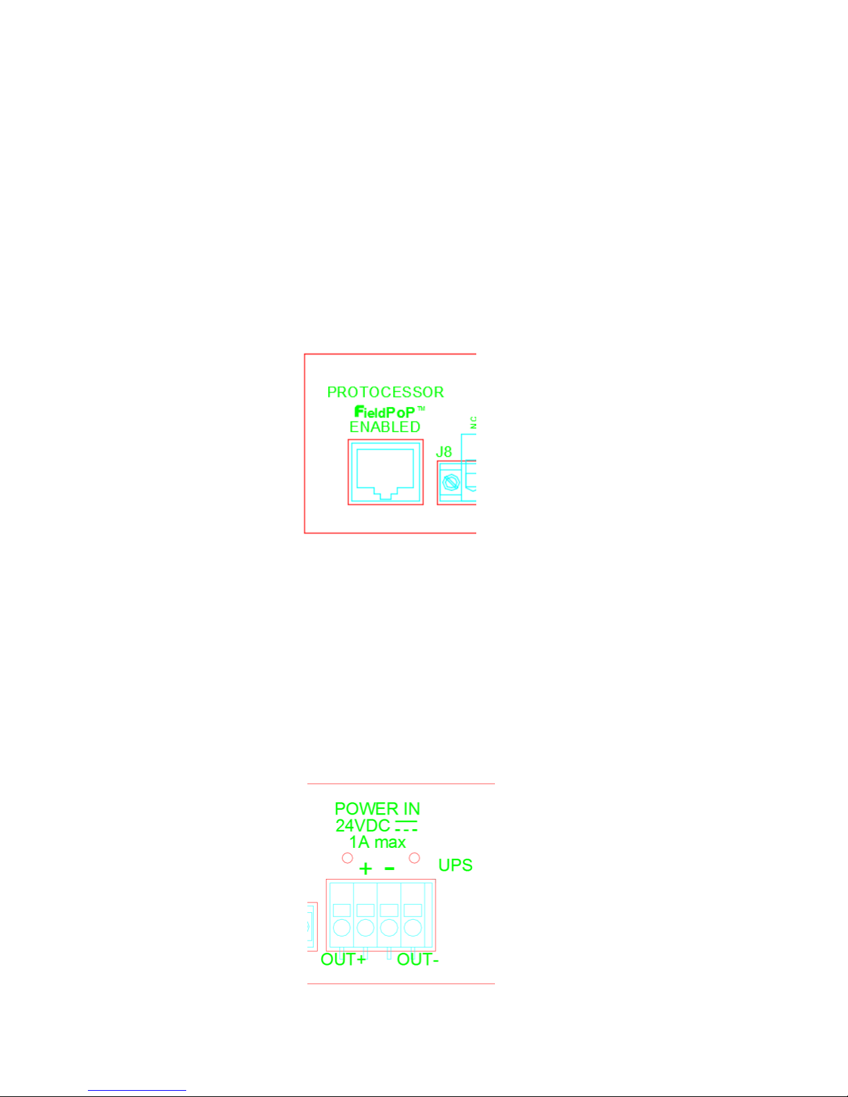
Protocessor. The Protocessor is used as a general purpose IP engine.
1

1. RESET Button
The Reset button is used to make a
hardware reset for servicing purposes.
2. Protocessor LEDs
The Protocessor LED’s display the status
of the Protocessor.
3. LED Indicators
The LED indicators display various
conditions and functions such as
network activity and relay status. See
“Using the System” for detailed
information.
4. Buttons
The buttons are used to make a number
of adjustments to the system without
using a computer.
5. LCD Display
The LCD displays various diagnostic
messages and configuration
information about the system.
2

6. Protocessor
Connect an Ethernet cable to access the
Protocessor.
(not supervised)
7. Aux Relays
The relays are general purpose relays.
(supervised by FACP)
8. RS232
For future use.
9. Inputs 1-4
Inputs 1-4 are general purpose inputs.
(supervised)
10. Inputs 5-8
Inputs 5-8 are general purpose inputs.
(supervised)
11. Inputs 9-12
Input 11: UPS AC Fault.
Input 12: UPS Battery Fault.
Inputs 9 & 10are general purpose inputs.
(supervised)
12. Data In/Out
Connect an OP Data Out to the I/O
expander Data In. Connect the I/O
expander Data Out to the next OP Data
In.
(supervised)
13. GND
Connect a common audio ground wire
from the GND connector to the first OP.
14. UPS Power In
Connect UPS power here or jumpers if a
UPS is not used.
(not supervised)
15. Power Input
Power cord connector (IEC 60320).
110-208 VAC.
(not supervised)
3

Wiring
4
5
Wiring
Power and Network connections:
1. Plug the unit into a standard outlet for 120VAC operation using the C13 to 5-15P power cord. For 208VAC
operation, plug the unit into an IEC C13 socket using the C13 to C14 power cord.
The system will be usable in approximately 10 seconds.
2. Connect a network cable to the unit’s Protocessor input. The Protocessor is the network server.
The Protocessor is pre-loaded with Lencore’s System Manager. System Manager allows
adjustment to the masking characteristics.
The unit includes a rear panel terminal block for the connection of an optional UPS. The
UPS output would connect to the terminal block: +24VDC to pin 2 and 24V COM to pin 3. When a
UPS is not used, jumpers In+ to Out+ and In- to Out- must be installed.
Use a UL 864 listed power supply for the UPS. The UPS must be 24VDC regulated until the power
supply batteries are exhausted. Lencore's PSM7A meets these requirements.
Incorporate a safety margin into the calculated amp-hour rating of 20%.
Maximum battery amp hour capacity supported by the charger to be 24 hours minimum.
Normal and alarm standby load is 100mA.
For US installations, the alarm time period is 15 minutes and for Canadian installations, the alarm time
period is 2 hours.
UPS connection:
Table of contents


