LenelS2 LNL-1300 User manual

Single Reader Interface Module LNL-1300 Series 3
Quick Reference
for rev. E and higher (SN > 2,000,000)
For detailed information, refer to the Hardware Installation Guide, DOC-600.
© 2020 Carrier. All Rights Reserved. LenelS2 is a part of Carrier. 1QR50L-1033E — revision 3.004
The LNL-1300 Board
The LNL-1300 reader interface provides a solution to the host system
integrator for interfacing to a TTL (D1/D0, Clock/Data), F/2F or RS-485
device, and door hardware. It also provides a tri-stated LED control and
buzzer control. Two (2) Form-C contact relay outputs may be used for strike
control or alarm signaling. Two (2) inputs are provided that can be used for
monitoring the door contact and request to exit push button. Input circuits
can be configured as unsupervised or supervised. Communication to the
controller is accomplished via a 2-wire RS-485 interface. The LNL-1300
requires 12 to 24 VDC for power.
LNL-1300 Hardware
The LNL-1300 requires filtered 12 to 24 VDC ± 10% for power. Two (2)
inputs are typically used for door contact and exit push button monitoring.
End of line resistors are required input supervision, shown below.
Note: The input power is passed through to the reader terminal strip
and is available for powering a reader. Readers that require
different voltage requirements must be powered separately. Care
must be taken to insure the input voltage is within the voltage
range of the reader. The reader power output terminal, TB4-6
(VO), is not current-limited.
TB1
GND
TR-
TR+
VO
D0
DAT
GND
D1
LED
CLK
BZR
TB4
2.35 [59.7]
2.75 [69.9]
3.85 [97.8]
0.20 [5.1]
0.20 [5.1]
J1
J2
D1
D2
D4 D3
TB3
TB2
I1
I1
I2
I2
GND
VIN
C
NC
NO
C
NO
NC
K2K1
4.25 [108]
K2
K1
S1
85674123
^
|
ON
12
3
The LNL-1300 Board Callouts
Callout Description
1 Status LEDs
2 Four (4) mounting holes (Ø0.156 [Ø4.0])
3 J2 - Tamper Input, Normally Open switch
1K,1%
1K,1%
1K,1%
1K,1% NC
NO EXIT REQUEST
NORMALLY OPEN
DOOR CONTACT
NORMALLY CLOSED
NORMALLY CLOSED
COMMON
NORMALLY OPEN
NORMALLY OPEN
NORMALLY CLOSED
COMMON
+12 to 24 VDC INPUT VOLTAGE
INPUT VOLTAGE RETURN
STRIKE RELAY (K1)
GROUND
BUZZER
LED
DATA1/CLOCK/TR+
DATA0/DATA/TR -
READER POWER
RS-485 INTERFACE
READER
TAMPER, NO
AUX. RELAY (K2)
TR -
GROUND
TR+
I2
I1
SIO COMMUNICATION
OPTIONAL EOL
SUPERVISION
SHOWN
TB1
GND
TR-
TR+
VO
D0
DAT
GND
D1
LED
CLK
BZR
TB4
J1
J2
85674123
^
|
ON
TO J2
TB3
TB2
I1
I1
I2
I2
GND
VIN
C
NC
NO
C
NO
NC
K2K1
K2
K1

Single Reader Interface Module LNL-1300 Series 3 Quick Reference
© 2020 Carrier. All Rights Reserved. LenelS2 is a part of Carrier. 2 QR50L-1033E — revision 3.004
Reader Wring
The reader port supports a reader with TTL (D1/D0, Clock/Data), F/2F, or
2-wire RS-485 signaling. (Refer to the reader manufacture specifications for
cabling requirements.) In the 2-wire LED mode the buzzer output is used to
drive the second LED. Reader port configuration is set via the host software.
Typical D1/D0 or Clock/Data Reader
Typical RS-485 Device (such as OSDP Reader)
Typical Unsupervised F/2F Reader
Typical Supervised F/2F Reader
Note: Jumper D1 to LED on supervised F/2F readers.
Door Strike Relay Wiring
Two (2) Form-C contact relays are provided for controlling door strike or
other devices. See specifications section for the relay contact ratings. Load
switching can cause abnormal contact wear and premature contact failure.
Switching of inductive loads (strike) also causes EMI (electromagnetic
interference) which may interfere with normal operation of other
equipment. To minimize premature contact failure and to increase system
reliability, a contact protection circuit must be used. The following two (2)
circuits are recommended. Locate the protection circuit as close to the load
as possible (within 12 inches [30 cm]), as the effectiveness of the circuit will
decrease if it is located far away.
Typical DC Door Strike Wiring
Diode Selection: Diode current rating: 1x strike current. Diode breakdown
voltage: 4x strike voltage. For 12 VDC or 24 VDC strike, diode 1N4002
(100V/1A) typical.
TB4 GND
D0/DAT/TR-
D1/CLK/TR+
VO
LED
BZR
1
BLK
GRN
WHT
RED
BRN
ORG
TB4
GND
D0/DAT/TR-
D1/CLK/TR+
VO
LED
BZR
1
TB4
D1
GROUND 1
F/2F Reader
+12 VDC
DO (GREEN LED)
GND
D0/DAT/TR-
D1/CLK/TR+
VO
LED
BZR
TB4
D1
GROUND
F/2F Reader
+12 VDC
DO(GREEN LED)
GND
D0/DAT/TR-
D1/CLK/TR+
VO
LED
BZR
1K,1%
1K,1%
1K,1%
1K,1%
1
1
2
Typical Supervised F/2F Reader Callouts
Callout Description
1 Door monitor switch
Normally Closed contact*
2 Request to Exit switch
Normally Open contact*
*Inputs on supervised F/2F readers may be unsupervised or supervised.
(Supervised is shown)
Door Strike Relay Wiring Callouts
Callout Description
1DCstrike
2Diode
3 Fuse
4 To DC power strike
+-
TB3
K2
K1
C
NC
NO
C
NO
NC
K2
K1
1
4
3
2

Single Reader Interface Module LNL-1300 Series 3 Quick Reference
© 2020 Carrier. All Rights Reserved. LenelS2 is a part of Carrier. 3 QR50L-1033E — revision 3.004
Communication Wiring
The LNL-1300 communicates to a Lenel intelligent controller (LNL-3300,
for example) via a half-duplex, multi-drop 2-wire RS-485 interface. The
total cable length is limited to 4000 feet (1219 m). A shielded cable of 24
AWG with characteristic impedance of 120 ohm is specified for the 2-wire
RS-485 interface. The last device on each end of the communication line
should have the terminator installed (install jumper J1).
Address, Baud Rate, and Encryption Configuration
Switch
Switches 1 to 5 select the device address. Switches 6 and 7 select the
communication baud rate. Switch 8 enables encrypted communication. All
other configuration settings are set via the host software.
Device Address
Communication Wiring Callouts
Callout Description
1 J1 - RS-485 communication terminator jumper
Install on last unit of the communication line.
2 Controller
3 To additional serial I/O units
DIP switch(es) Used to configure:
1, 2, 3, 4, 5 Device communication address (0-31)
6, 7 Communication baud rate
8Downstream encryption (available with OnGuard®2009
or later)
LNL-1300
TR-
GND
TR+
LNL-1300
TB1
GND
TR-
TR+
VO
D0
J1
J2
85674123
^
|O
N
TB1
GND
TR-
TR+
VO
D0
J1
J2
85674123
^
|O
N
1
2
3
Address DIP switch
5: 4: 3: 2: 1:
0 off off off off off
1 off off off off ON
2 off off off ON off
3 off off off ON ON
4 off off ON off off
5 off off ON off ON
6offoffONONoff
7 off off ON ON ON
8 off ON off off off
9 off ON off off ON
10 off ON off ON off
11 off ON off ON ON
12 off ON ON off off
13 off ONONoff ON
14 off ONONONoff
15 off ONONONON
16 ON off off off off
17 ON off off off ON
18 ON off off ON off
19 ON off off ON ON
20 ON off ON off off
21 ON off ON off ON
22 ON off ON ON off
23 ON off ON ON ON
24 ON ON off off off
25 ON ON off off ON
26 ON ON off ON off
27 ON ON off ON ON
28 ON ON ON off off
29 ON ON ON off ON
30 ON ON ON ON off
31 ON ON ON ON ON

Single Reader Interface Module LNL-1300 Series 3 Quick Reference
© 2020 Carrier. All Rights Reserved. LenelS2 is a part of Carrier. 4 QR50L-1033E — revision 3.004
Communication Baud Rate
Bus Encryption
Status LEDs
Power-up: All LEDs OFF.
Initialization: Once power is applied, initialization of the module begins.
The D1 LED is turned ON at the beginning of initialization.
Run time: After the above sequence, the LEDs have the following
meanings:
D1 LED: Heartbeat and On-Line Status:
• Off-line: 1 second rate, 20% ON, 80% OFF
• On-line:
- Non-encrypted communication: 1 second rate, 80% ON, 20%
OFF
- Encrypted communication: 0.1 sec ON, 0.1 sec OFF, 0.1 sec
ON, 0.1 sec OFF, 0.1 sec ON, 0.1 sec OFF, 0.1 sec ON, 0.3 sec
OFF
D1 LED: Error Indication:
Waiting for application firmware to be downloaded: 0.1 sec ON, 0.1 sec
OFF
D2 LED: Serial I/O Communication Port Status:
Indicates communication activity on the serial I/O communication port
Specifications
The LNL-1300 is for use in low voltage, class 2 circuit, only. These
specifications are subject to change without notice.
• Primary power: 12 to 24 VDC ± 10%, 150 mA maximum (plus reader
current)
• Outputs: Two (2) Form-C relays:
- K1: Normally Open (NO) contact: 5 A @ 30 VDC resistive
Normally Closed (NC) contact: 3 A @ 30 VDC resistive
- K2: 1 A @ 30 VDC resistive
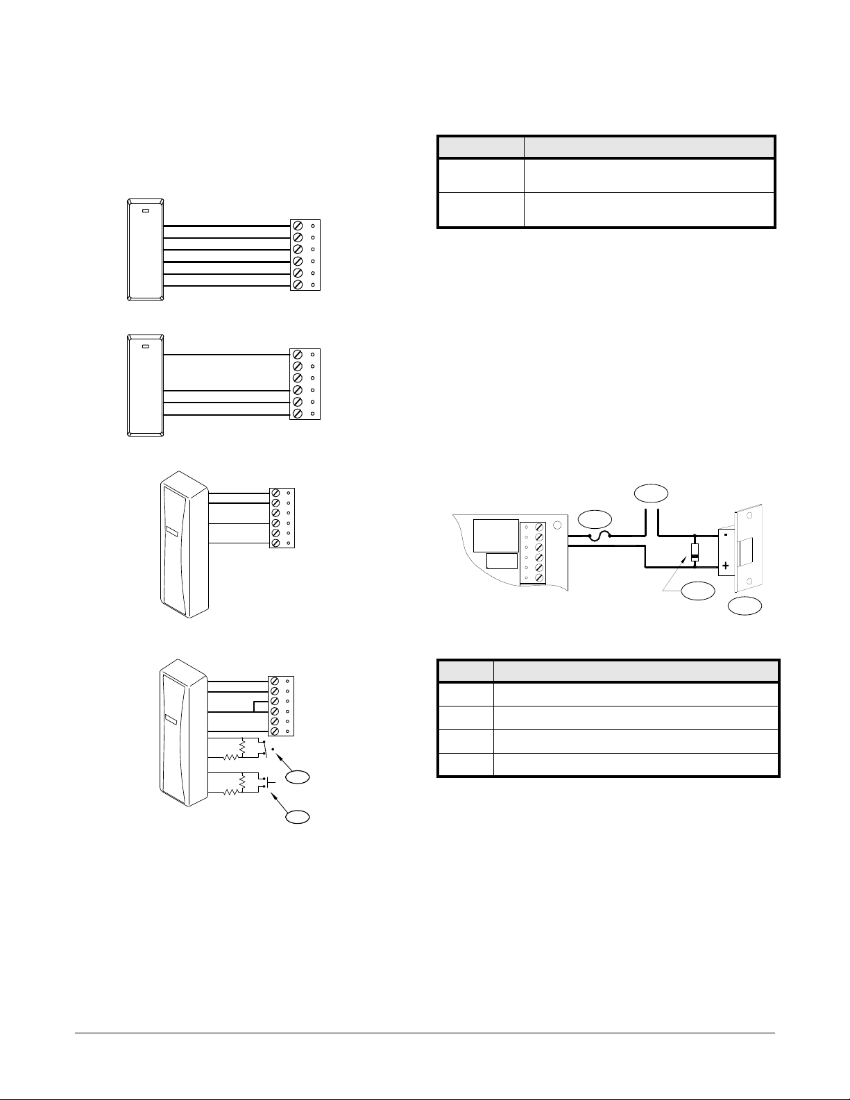
• Inputs:
- Two (2) unsupervised/supervised, standard EOL, 1k/1k ohm,
1%, ¼ watt
- One (1) unsupervised, dedicated for cabinet tamper
• Reader interface:
- Reader power: 12 to 24 VDC ± 10% (input voltage passed
through)
- Reader LED output: TTL compatible, high > 3 V, low < 0.5 V,
5 mA source/sink maximum
- Buzzer output: Open collector, 12 VDC open circuit maximum,
40 mA sink maximum
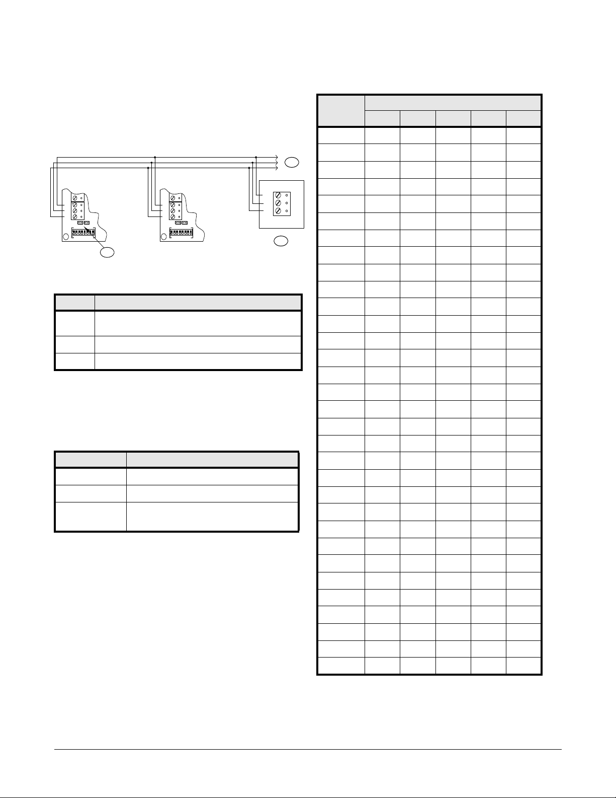
- Data inputs: TTL compatible, F/2F or 2-wire RS-485
• Communication: 2-wire RS-485: 9600, 19200, 38400, or 115200 bps
• Cable requirements:
- Power: 1 twisted pair, 18 AWG
- RS-485 I/O devices: 1 twisted pair with drain wire and shield,
24 AWG, 120 ohm impedance, 4000 feet (1219 m) maximum
- Alarm inputs: 1 twisted pair per input, 30 ohms maximum
- Output: As required for the load
- Reader data (TTL): 6-conductor, 18 AWG, 500 feet (150 m)
maximum
- Reader data (F/2F): 4-conductor, 18 AWG, 500 feet (150 m)
maximum
- Reader data (RS-485): 24 AWG, 120 ohm impedance, twisted
pair with drain wire and shield, 2000 feet (610 m) maximum
Mechanical:
- Dimension: 4.25 x 2.75 x 1 in. (108 x 70 x 25.4 mm)
- Weight: 4 oz. (120 g) nominal
• Environmental:
- Temperature: -55 to +85°C storage, -40 to +75°C operating
- Humidity: 5% to 95% RHNC
UL 294, 7th edition Performance Levels:
Note: Outputs are Power limited/class 2 when powered by external
power limited/class 2 power supply model LNL-AL400ULX or
LNL-AL600ULX-4CB6.
Baud rate DIP switch 6: DIP switch 7:
38,400 bps ON ON
19,200 bps off ON
9600 bps ON off
115,200 bps off off
Bus communications DIP switch 8:
(OnGuard 2009
or later)
DIP switch 8:
(prior to
OnGuard 2009)
Encryption is not required off Normal operation
Encryption is required ON Not allowed
Feature Level
Standby Power I
Endurance IV
Line Security I
Destructive Attack I

Single Reader Interface Module LNL-1300 Series 3 Quick Reference
© 2020 Carrier. All Rights Reserved. LenelS2 is a part of Carrier. 5 QR50L-1033E — revision 3.004
Regulatory Information
FCC Compliance
This device complies with part 15 of the FCC Rules. Operation is subject to
the following two conditions: (1) This device may not cause harmful
interference, and (2) this device must accept any interference received,
including interference that may cause undesired operation.
Liability
It is expressly understood and agreed that the interface should only be used
to control exits from areas where an alternative method for exit is available.
This product is not intended for, nor is rated for operation in life-critical
control applications. LenelS2 is not liable under any circumstances for loss
or damage caused by or partially caused by the misapplication or
malfunction of the product. LenelS2’s liability does not extend beyond the
purchase price of the product.
Certifications
For certification information, refer to the hardware documentation for the
host application.
Product Warnings and Disclaimers
THESE PRODUCTS ARE INTENDED FOR SALE TO, AND
INSTALLATION BY, AN EXPERIENCED SECURITY
PROFESSIONAL. LENELS2 CANNOT PROVIDE ANY ASSURANCE
THAT ANY PERSON OR ENTITY BUYING ITS PRODUCTS,
INCLUDING ANY “AUTHORIZED DEALER”, IS PROPERLY
TRAINED OR EXPERIENCED TO CORRECTLY INSTALL SECURITY
RELATED PRODUCTS.
For more information on warranty disclaimers and product safety
information, please check https://firesecurityproducts.com/en/policy/
product-warning or scan the following code:

Single Reader Interface Module LNL-1300 Series 3 Quick Reference
© 2020 Carrier. All Rights Reserved. LenelS2 is a part of Carrier. 6 QR50L-1033E — revision 3.004
Table of contents
Other LenelS2 Recording Equipment manuals
Popular Recording Equipment manuals by other brands

HEKA Elektronik
HEKA Elektronik LIH 8+8 manual

McCauley Sound
McCauley Sound M Series Operation manual

Fisher
Fisher K-10 Spacexpander user guide

TimeLine
TimeLine Micro Lynx ACG-1 Option Card installation guide

Xaoc Devices
Xaoc Devices KAMIENIEC Operator's manual

Hughes & Kettner
Hughes & Kettner SPIRIT AMPMAN Series manual