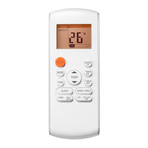
Lennox Armonia User manual

Infrared remote control - ARMONIA
ARMONIA IRC-IOM-0610-E
User manual
Manuale d’uso
User manual
Manuel d’utilisation
Bedienungsanleitung
Manual de usuario
Gebruikershandleiding
I
GB
F
G
S
D


1
INDICE
Scopo
Configurazione
Montaggio del ricevitore sulla
plafoniera
Montaggio della plafoniera sul
Cassette
Scheda elettronica
Funzione dei contatti ausiliari
Impostazione dei Dip di
configurazione
Configurazione di default
Funzione Autofan
Funzionamento Master-Slave
Note di installazione
Messa a terra della rete
Accessori
Schemi di collegamento
Batterie
Note generali
Impostazione orologio
Impostazione del set desiderato
Impostazione della ventilazione
Modalità di funzionamento
Timer
2
3
4
4
5
6
7
7
8
9
11
12
13
14
15
16
18
19
20
21
22
SCOPO
SI RACCOMANDA
DI LEGGERE ATTENTAMENTE
QUESTE ISTRUZIONI
PRIMA DI UTILIZZARE
IL TELECOMANDO
QUESTO TELECOMANDO
SERVE UNICAMENTE
PER PILOTARE
GLI APPARECCHI CASSETTE
CONTENTS
Scope
Configuration
Mounting the receiver on the
support
Mounting the support on the
Cassette
Electronic board
Function of the auxiliary
contacts
Setting the configuration
dipswitches
Default configuration
Autofan function
Master-Slave operation
Installation notes
Earthing the network
Accessories
Connection diagram
Batteries
General notes
Setting the clock
Setting the set point
Setting the fan mode
Operating modes
Timer
2
3
4
4
5
6
7
7
8
9
11
12
13
14
15
16
18
19
20
21
22
SCOPE
READ
THESE INSTRUCTIONS
CAREFULLY
BEFORE USING
THE REMOTE CONTROL
THIS REMOTE CONTROL
CAN ONLY BE USED
TO CONTROL
THE CASSETTE APPLIANCES
1A
SOMMAIRE
INHALT ÍNDICE INHOUD
BUT
ZWECKBESTIMMUNG
OBJETIVO DOEL
But
Configuration
Montage du récepteur sur le
support
Montage du support sur la
Cassette
Carte électronique
Fonction des contacts
auxiliaires
Programmation des dipswitches
Configuration par défaut
Fonction Autofan
Fonctionnement Maître-Esclave
Installation
Mise à la terre du réseau
Accessoires
Schémas de raccordement
Piles
Notes
Programmation horloge
Programmation de la consigne
voulue
Programmation de la ventilation
Modes de fonctionnement
Minuterie
2
3
4
4
5
6
7
7
8
9
11
12
13
14
15
16
18
19
20
21
22
Zweckbestimmun
Konfiguration
Montage des Empfangsteils
an der Deckenblende
Montage der Deckenblende
am Kassetten-Klimakonvektor
Elektronikplatine
Funktion der Hilfskontakte
Einstellung der
Konfigurations-Dip-Switches
Default-Konfiguration
Autofan Funktion
Master-Slave Funktion
Anmerkungen zur Installation
Erden des Netzes
Zubehöre
Schaltpläne
Batterien
Allgemeine Anmerkungen
Einstellung der Uhr
Einstellung des gewünschten
Sollwerts
Einstellung der Belüftung
Betriebsmodus
Timer
2
3
4
4
5
6
7
7
8
9
11
12
13
14
15
16
18
19
20
21
22
Objetivo
Configuración
Montaje del receptor en el
plafón
Montaje del plafón en el
Cassette
Tarjeta electrónica
Función de los contactos
auxiliares
Programación
de los Dip de configuración
Configuración por defecto
Función Autofan
Funcionamiento Master-Slave
Notas de instalación
Puesta a tierra de la red
Accesorios
Esquemas de conexión
Baterías
Notas generales
Programación del reloj
Programación
del punto de ajuste deseado
Programación de la
ventilación
Modalidad de funcionamiento
Temporizador
2
3
4
4
5
6
7
7
8
9
11
12
13
14
15
16
18
19
20
21
22
Doel
Configuratie
Montage ontvanger op
plafondelement
Montage plafondelement op
Cassette
Elektronische fiche
Functie van de hulpcontacten
Instelling van de
configuratieschakelaars
Defaultconfiguratie
Functie Autofan
Werking Master-Slave
Installatienota
Aarding netwerk
Accessoires
Aansluitschema’s
Batterijen
Algemene opmerkingen
Instelling klok
Instelling gewenste set
Instelling ventilatie
Werkwijze
Timer
2
3
4
4
5
6
7
7
8
9
11
12
13
14
15
16
18
19
20
21
22
NOUS VOUS RECOMMANDONS
DE LIRE ATTENTIVEMENT
CES INSTRUCTIONS
AVANT D’UTILISER
LA TÉLÉCOMMANDE
CETTE TÉLÉCOMMANDE
EST DESTINÉE UNIQUEMENT
À PILOTER
LES APPAREILS CASSETTE
VOR EINSATZ
DER FERNBEDIENUNG
SOLLTE
DIESE BETRIEBSANLEITUNG
SORGFÄLTIG GELESEN WERDEN.
DIESE FERNBEDIENUNG
DIENT AUSSCHLIESSLICH
ZUM STEUERN DER
KASSETTEN-KLIMAKONVEKTOREN.
LE RECOMENDAMOS
QUE LEA ATENTAMENTE
ESTAS INSTRUCCIONES
ANTES
DE USAR EL MANDO A DISTANCIA
ESTE MANDO A DISTANCIA
SIRVE ÚNICAMENTE
PARA HACER FUNCIONAR
LOS APARATOS CASSETTE
HET IS RAADZAAM
DEZE HANDLEIDING AANDACHTIG
TE LEZEN ALVORENS
DE AFSTANDSBEDIENING
TE GEBRUIKEN
DEZE AFSTANDSBEDIENING
DIENT UITSLUITEND
OM DE APPARATEN
CASSETTE TE BEDIENEN

2
CONFIGURAZIONE
Gli apparecchi Cassette con Tele-
comando vengono consegnati con
i materiali illustrati a lato.
Dopo aver aperto e tolto l’imballo,
accertarsi che il contenuto sia
quello richiesto e che sia integro.
In caso contrario, rivolgersi al
rivenditore ove si è acquistato
l’apparecchio.
Questolibrettodeveaccompagnare
sempre l’apparecchio in quanto
parte integrante dello stesso.
CONFIGURATION
The Cassette appliances with
remote control are delivered with
the materials shown to the side.
After having opened and removed
the packaging, make sure that the
contents are complete and intact.
Otherwise contact the reseller
where the appliance was purcha-
sed.
This booklet must always accompany
the appliance, being considered
LEGENDA:
A= Cassette
B= Ricevitore
C= Telecomando
D= Batterie (tipo AAA1,5 Volt)
KEY:
A= Cassette
B= Receiver
C= Remote control
D= Batteries (type AAA1.5 Volt)
2A
CONFIGURATION KONFIGURATION CONFIGURACIÓN CONFIGURATIE
Les appareils Cassette à Télé-
commande
sont
livrés avec les
matériels ci-contre.
Après avoir ouvert et retiré
l’emballage, s’assurer que le contenu
est en bon état et qu’il correspond
bien à ce qui a été acheté.
Si ce n’est pas le cas s’adresser au
revendeur chez lequel l’appareil a
été acheté.
Ce livret doit toujours accompagner
l’appareil car il fait partie intégrante
de celui-ci.
Die Kassetten-Klimakonvektoren
mit
Fernbedienung werden komplett
mit dem seitlich abgebildeten
Material geliefert.
Nach dem Auspacken kontrollieren,
ob der Inhalt der Bestellung
entspricht und unversehrt ist.
Im gegenteiligen Fall wenden Sie
sich an Ihren Händler.
Diese Betriebsanleitung ist wesentlicher
Bestandteil des Gerätes und muss
folglich immer zusammen mit diesem
verwahrt werden.
Los aparatos Cassette con mando
a distancia se entregan con los
materiales que figuran al lado.
Después de haber retirado el
embalaje, compruebe que el
contenido sea el solicitado y que
esté intacto.
En caso contrario, diríjase al esta-
blecimiento donde ha comprado
el aparato.
Este manual debe acompañar
siempre al aparato ya que forma
parte del mismo.
De apparaten Cassette met
Afstandsbedieningwordengeleverd
met het hiernaast geïllustreerd
materiaal.
Na de verpakking te hebben
verwijderd, controleer of de inhoud
ervan intact is.
Mocht de inhoud beschadigd zijn,
wend u dan tot het verkooppunt.
Deze handleiding dient het apparaat
altijd te vergezellen en maakt er
wezenlijk deel van uit.
LÉGENDE:
A= Cassette
B= Récepteur
C= Télécommande
D= Piles (type AAA 1,5 Volt)
LEGENDE:
A = Kassetten-Klimakonvektor
B = Empfangsteil
C = Fernbedienung
D = Batterien (Typ AAA 1,5 Volt)
LEYENDA:
A = Cassette
B =Receptor
C =Mando a distancia
D= Baterías (tipo AAA1,5 Volt)
LEGENDE:
A =Cassette
B = Ontvanger
C =Afstandsbediening
D= Batterijen (type AAA1,5 Volt)

3
MONTAGGIO
DEL RICEVITORE
SULLA PLAFONIERA
Dopo aver installato l’apparecchio
Cassette a soffitto, seguire i
seguenti passaggi per fissare la
plafoniera:
1- Appoggiare la plafoniera (dal
lato opposto al ricevitore) al
Cassette.
2- Fissare provvisoriamente
la plafoniera con l’apposita
molla.
3- Connettere il terminale
del ricevitore al terminale
del cavo proveniente dalla
scheda.
4- Appoggiare l’intera plafoniera
al Cassette e fissarla provvi-
soriamente con la seconda
molla.
5- Fissare con le apposite viti la
plafoniera al Cassette (vedi
manuale di installazione e
manutenzione Cassette).
MOUNTING
THE RECEIVER
ON THE SUPPORT
Fissare il ricevitore sulla plafo-
niera come mostrato in Figura
“1”.
Non si risponde in caso di
danni provocati da modifiche o
MONTAGGIO
DELLA PLAFONIERA
SUL CASSETTE
MOUNTING
THE SUPPORT
ON THE CASSETTE
After having installed the Cassette
appliance on the ceiling, proceed
as described below to mount the
support:
1- Rest the support (the side
opposite the receiver) on the
Cassette.
2-
Temporarily fasten the support
using the spring.
3- Connect the terminal on the
receivertotheterminalonthe
cable running to the board.
4- Rest the entire support on
the Cassette and fasten it
temporarily using the second
spring.
5- Fasten the support to the
Cassette using the special
screws (see the Cassette
installation and maintenance
manual).
Fasten the receiver onto the
support as shown in Figure “1”.
Noliabilityisacceptedfor damage
caused by modifications to or
tampering with the appliance.
3A
MONTAGE
DU RECEPTEUR
SUR LE SUPPORT
MONTAGE DES
EMPFANGSTEILS AN
DER DECKENBLENDE
MONTAJE
DEL RECEPTOR
EN EL PLAFÓN
MONTAGE
ONTVANGER OP
PLAFONDELEMENT
MONTAGE
DU SUPPORT
SUR LA CASSETTE
Après avoir installé l’appareil Cas-
sette au plafond, fixer le plafonnier
en procédant comme suit:
1- Poser le support (du côté
opposé au récepteur) sur la
Cassette.
2-
Fixer provisoirement le support
à l’aide du ressort.
3-
Raccorder la borne du récepteur
à la borne du câble provenant
de la carte.
4- Poser tout le support sur la
Cassette et le fixer provisoi-
rement à l’aide du deuxième
ressort.
5- A l’aide des vis fournies fixer
le support à la Cassette (voir
manuel installation et entretien
Cassette).
Fixer le récepteur sur le plafon-
nier voir fig. “1”.
La société ne répond pas des
dommages causés par des
modifications ou détériorations de
l’appareil.
MONTAGE DER DECKEN-
BLENDE AM KASSETTEN-
KLIMAKONVEKTOR
Nachdem der Kassetten-Klimakonvektor
an der Decke installiert wurde, die
Deckenblende wie folgt befestigen:
1- Die Deckenblende (an der
dem Empfangsteil entgegen
gesetzten Seite) am Kassetten
-
Klimakonvektor auflegen.
2-
Die Deckenblende mit der
dafür vorgesehenen Klammer
provisorisch befestigen.
3-
Die Anschlussklemme des Empfangsteils
mit der Anschlussklemme des aus
der Platine kommenden Drahts
verbinden.
4- Die ganze Deckenblende an
demKassetten-Klimakonvektor
anlegen und mit der anderen
Klammer provisorisch befestigen.
5-
Nun die Deckenblende mit
den speziellen Schrauben am
Kassetten-Klimakonvektor
befestigen (siehe Installations-
und Wartungs- handbuch des
Kassetten-Klimakonvektors).
Das Empfangsteil an der Deckenblende
befestigen, wie aus der Abbildung
“1” ersichtlich
.
Der Hersteller haftet nicht für
solche Schäden, die durch die
Veränderung oder die Manipulierung
des Geräts entstehen.
MONTAJE
DEL PLAFÓN
EN EL CASSETTE
Después de haber instalado el aparato
Cassette en el techo, realice los
siguientes pasos para fijar el plafón:
1- Apoye el plafón (por el lado
opuesto al receptor) sobre el
Cassette.
2-
Fije provisionalmente el plafón
con el muelle correspondiente.
3-
Conecte el terminal del receptor
al terminal del cable procedente
de la tarjeta.
4- Apoye toda la plataforma
sobre el cassette y fíjela
provisionalmenteconelsegundo
muelle.
5- Fije el plafón al Cassette
mediante los tornillos
correspondientes (ver manual
de instalación y mantenimiento
del Cassette).
Fije el receptor al plafón como
indica la figura “1”.
La empresa no se hace responsable
en caso de daños provocados por
modificaciones o manipu-laciones
del aparato.
MONTAGE
PLAFONDELEMENT
OP CASSETTE
Na het apparaat Cassette te hebben
geïnstalleerd aan het plafond, volg de
volgende stappen voor de montage van
het plafondelement:
1- Breng het plafondelement
(aan de zijde tegenover de
ontvanger) tegen de Cassette.
2-
Bevestig het plafondelement
voorlopig met de daartoe
bestemde veer.
3-
Sluit de klem van de ontvanger
aan op de klem van de kabel
afkomstig van de fiche.
4- Breng het volledig plafondelement
tegen de Cassette en bevestig
voorlopig met behulp van de tweede
veer.
5- Bevestig het plafondelement met
behulp van de schroeven aan
Cassette (zie handleiding installatie
en onderhoud Cassette).
Bevestig de ontvanger op het
plafondelement, zoals geïllustreerd
in figuur “1”.
De fabrikant kan niet aansprakelijk
worden gesteld voor schade
veroorzaakt door wijzigingen
aangebracht aan het apparaat.

4
SCHEDA
ELETTRONICA
LEGENDA:
D1 =
Dip Switch di configurazione
D2 = Dip Switch di indirizzo
J1 = Jumper JMP3
M1 =
Morsettiera di collegamento
linea e valvole acqua
T1 = Sonda aria (posta in
ripresa dell’apparecchio)
T2 =
Sonda Change-Over (optional)
T3 = Sonda di minima (di
default non attiva)
AB = Morsetti A-B per il collega-
mento seriale RS 485
CF = F2-F2 Contatto pulito
finestra aperta / presenza
persona. Se aperto l’unità
si ferma
CA = (F1) - (-12V dc) Contatto
pulito per accensione /
spegnimento con pulsante
instabile
SE = Alimentazione 12V dc
(max 60 mA) per il
collegamento sensori
esterni
ELECTRONIC
BOARD
KEY:
D1 = Configuration dipswitches
D2 = Address dipswitches
J1 = Jumper JMP3
M1 =
Terminal block for connecting
the line and water valves
T1 = Air probe (fitted at the
appliance intake)
T2 = Change-Over probe
(optional)
T3 = Minimum probe (disabled
by default)
AB = Terminals A-B for the
RS485 serial connection
CF = F2-F2 Window open /
person presence voltage-
free contact. If open the
unit stops
CA = (F1) - (-12Vdc) Voltage-
free contact for On / Off
with unsteady button
SE = 12Vdc power supply (max
60mA) for connecting
external sensors
4A
CARTE
ELECTRONIQUE
ELEKTRONIKPLATINE
TARJETA
ELECTRÓNICA ELEKTRONISCHE
FICHE
LÉGENDE:
D1 =
Dip Switch de configuration
D2 = Dip Switch d’adresse
J1 = Jumper JMP3
M1 = Bornier de raccordement
ligne et vannes eau
T1 = Sonde air (placée sur la
reprise de l’appareil)
T2 = Sonde Change-Over
(option)
T3 = Sonde de température
minimale (par défaut
pas active)
AB =
Bornes A-B pour le raccor-
dement série RS 485
CF = F2-F2 Plot libre fenêtre
ouverte /détection présence.
S’il est ouvert l’unité s’arrête
CA = (F1) - (-12V DC) Plot
libre pour mise en marche
/arrêt avec bouton instable
SE = Alimentation 12 V DC
(maxi 60 mA) pour le
raccordement capteurs
extérieurs
LEGENDE:
D1 = Konfigurations-Dip-Switch
D2 = Adresse-Dip-Switch
J1 = Jumper JMP3
M1 = Anschluss-Klemmleiste
der Stromleitung und
Wasserventile
T1 = Lufttemperaturfühler (am
Ansaugteil des Geräts)
T2 =
Change-Over-Fühler (Option)
T3 = Mindesttemperaturfühler
(standardmäßig nicht aktiv)
AB = Klemmen A-B für den
seriellen Anschluss RS 485
CF = F2-F2 Kontakt offenes
Fenster/Personal-
anwesenheit. Wenn offen,
schaltet sich das Gerät aus
CA = (F1)- (-12V dc) Kontakt
für Ein-/Ausschalten mit
Kippschalter
SE = 12V dc Einspeisung (max.
60 mA) für den Anschluss
der externen Sensoren)
LEYENDA:
D1 =
Dip Switch de configuración
D2 = Dip Switch de dirección
J1 = Jumper JMP3
M1 =
Caja de bornas de conexión
líneas y válvulas agua
T1 = Sonda aire (colocada en
reanudación del aparato)
T2 = Sonda Change-Over
(opcional)
T3 = Sonda de mínima (por
defecto no activa)
AB = Bornas A-B para la
conexión en serie RS 485
CF = F2-F2 Contacto limpio
ventana abierta /
presencia persona. Si está
abierto la unidad se para
CA = (F1)- (-12V dc) Contacto
limpio para encendido /
apagado con pulsador
inestable
SE = Alimentación 12V dc (máx.
60 mA) para la conexión
de sensores externos)
LEGENDE:
D1 =
Dimschakelaar configuratie
D2
= Dimschakelaar bestemming
J1 = Jumper JMP3
M1 = Klemmenbord lijn en
waterklep
T1 = Luchtsonde (vlakbij het
apparaat)
T2
= Sonde Change-Over
(optie)
T3 = Minimumsonde (default
niet actief)
AB = Klemmen A-B voor de
seriële aansluiting RS 485
CF = F2-F2 Schoon contact
open raam / aanwezigheid
persoon. Indien open stopt
de eenheid
CA = (F1)- (-12V dc) Schoon
contact voor inschakeling /
uitschakeling met
instabiele drukknop
SE = Voeding 12V dc (max. 60
mA) voor aansluiting
externe sensoren)

5
FUNZIONE DEI
CONTATTI AUSILIARI
Contatto CF (F2-F2): è un contatto
pulito che può essere utilizzato
per l’accensione / spegnimento
dell’apparecchio in abbinamento a:
- un contatto pulito di un orologio
- un relè remoto
- un interruttore
- un contatto finestra aperta
- sonde presenza persona
- un altro sistema
A contatto chiuso l’apparecchio
funziona.
A contatto aperto l’apparecchio si
ferma.
Contatto CA [F1 - (-12V)]: è un
contatto pulito che può essere utiliz-
zato per l’accensione/spegnimento
dell’apparecchio a mezzo di un inter-
ruttore instabile o controllo esterno
che produca una chiusura momen-
tanea, con successiva riapertura, del
contatto.
Contatto SE [(+12V) - (-12V)]:
fornisce una tensione di 12 V dc
per poter alimentare apparecchiature
elettroniche esterne quali sonde
presenza persona.
Massima corrente erogabile 60
mA.
Il relativo consenso dovrà essere
collegato ai contatti F2-F2 o F1 -
(-12V) sopra descritti.
FUNCTION OF THE
AUXILIARY CON-
Contact CF (F2-F2): voltage-free
contact that can be used to switch
the appliance On / Off in combination
with:
-
the voltage-free contact of a timer.
- a remote relay
- a switch
- a window open contact
- person presence sensors
- other systems
When the contact is closed the
appliance can operate.
When the contact is open the
appliance is stopped.
Contact CA [F1 - (-12V)]: voltage-
free contact that can be used to
switch the appliance On / Off by an
unsteady switch or external control
with the momentary closing, and
subsequent reopening, of the contact.
Contact SE [(+12V) - (-12V)]:
provides 12Vdc for powering external
electronic equipment, such as person
presence sensors.
Maximum current available 60mA.
The trigger must be connected
to contacts F2-F2 or F1 - (-12V)
described above.
5A
FONCTION DES
CONTACTS AUXILIAI-
RES
FUNKTION DER
HILFSKONTAKTE FUNCIONES DE LOS
CONTACTOS AUXILIARES
FUNCTIE VAN DE
HULPCONTACTEN
Contact CF (F2-F2): c’est un
contact libre qui peut être utilisé
pour la mise en marche / l’arrêt de
l’appareil connecté à:
- un contact libre d’une horloge
- d’un relais à distance
- d’un interrupteur
- d’un contact fenêtre ouverte
- sonde détection de présence
- autre système
Contact fermé l’appareil fonc-
tionne.
Contact ouvert l’appareil s’arrête.
Contact CA [F1 - (-12V)]: c’est un
contact libre qui peut être utilisé
pour la mise en marche / l’arrêt de
l’appareil au moyen d’un interrup-
teur instable ou contrôle externe
produisant la fermeture momen-
tanée, puis la réouverture, du con-
tact.
Contact SE [(+12V) - (-12V)]:
fournit une tension 12V DC pour
pouvoir alimenter des appareils
électroniques externes tels que des
sondes de détection de présence.
Courant maximal fourni 60 mA.
L’actionnement devra être raccordé
aux contacts F2-F2 o F1 - (-12V)
décrits ci-dessus.
Kontakt CF (F2 – F2): einem Kontakt,
der zum Ein-/Ausschalten des
Geräts verwendet werden kann, in
Kombination mit:
- einem Kontakt einer Uhr
- einem entfernten Relais
- einem Schalter
-
einem Kontakt für offenes Fen-
ster
- Personalanwesenheitsmelder
- anderem System
BeigeschlossenemKontaktfunktioniert
das Gerät.
Bei offenem Kontakt schaltet sich
das Gerät aus.
Kontakt CA [F1 – (-12V)]: ein
Kontakt, der zum Ein-/Ausschalten
des Geräts mit einem Taster
oder
einer externen Steuerung
eingesetzt
werden kann, welche(r)
ein momentanes Schließen und
folgendes erneutes Öffnen des
Kontakts erzeugt.
Kontakt SE [(+12V) – (-12V)]:
liefert eine 12 V dc Spannung
zur Versorgung der externen
elektronischen Einrichtungen, wie
die Personalanwesen-heitsmelder.
Lieferbarer max. Strom 60 mA.
Die entsprechende Freigabe wird
an die vorstehend beschriebenen
Kontakte F2-F2 oder F1-(-12V)
angeschlossen.
Contacto CF (F2 – F2): es un
contacto limpio que puede usarse
para el encendido / apagado del
aparato en combinación con:
- un contacto limpio de un reloj.
- un relé remoto
- un interruptor
- un contacto ventana abierta
- una sonda presencia persona
- otro sistema
Con el contacto cerrado el aparato
funciona.
Con el contacto abierto el aparato se
para.
Contacto CA [F1 – (-12V)]: es un
contacto limpio que puede usarse
para el encendido/apagado del
aparato mediante un interruptor
inestable o control externo que
produzca un cierre momentáneo,
con la posterior reapertura, del
contacto.
Contacto SE [(+12V) – (-12V)]:
proporciona una tensión de 12 V dc
para poder alimentar equipos
electrónicos externos como sondas
presencia persona.
Máxima corriente de erogación 60 mA.
La autorización correspondiente
deberá conectarse a los contactos
F2-F2 o F1-(-12V) anteriormente
descritos.
Contact CF (F2 – F2): een schoon
contact dat gebruikt kan worden voor
de inschakeling / uitschakeling van het
apparaat in combinatie met:
- een schoon contact van een klok
- een afstandsrelais
- een schakelaar
- een contact open raam
- sonde aanwezigheid persoon
- ander systeem
Bij gesloten contact werkt het apparaat.
Bij open contact stopt het apparaat.
Contact CA [F1 – (-12V)]: een schoon
contact dat gebruikt kan worden voor
de inschakeling/uitschakeling van het
apparaat met behulp van een instabiele
schakelaar of externe bediening die
zorgt voor een tijdelijke sluiting en
daaropvolgende opening van het contact.
Contact SE [(+12V) – (-12V)]: levert een
spanning van 12V dc voor de voeding
van de externe elektronische apparatuur
zoals sondes die de aanwezigheid van
personen opsporen.
Maximaal afgegeven stroom 60 mA.
Derelatieve apparatuur wordt aangesloten
op de hierboven beschreven contacten
F2-F2 of F1-(-12V).

ON
OFF *
x
x
x
x
x
x
x
x
x
x
x
x
ON *
OFF
x
x
x
x
x
x
x
x
x
x
x
x
ON
OFF *
x
x
x
x
x
x
x
x
x
x
x
x
ON *
OFF
OFF
OFF
x
x
x
x
x
x
x
x
x
ON
OFF *
ON
x
x
x
x
x
x
x
x
x
OFF
ON
ON
x
x
x
x
x
x
x
x
x
x
x
x
x
x
x
x
x
x
x
x
x
x
x
x
ON
OFF *
12345678
Configurazione / Configuration / Configuration Posizione Switches / Switch position / Position Switches
Impianto 4 Tubi
4-pipe system
Installation 4 tubes
Impianto 2 Tubi
2-pipe system
Installation 2 tubes
Esclusione T3
Disable T3
Exclusion T3
Sonda di minima attiva
Enable cut-out thermostat
Sonde de limitation basse
Senza telecomando
Without remote control
Sans télécommande
Con telecomando
With remote control
Avec télécommande
Ventilazione continua
Fan always on
Ventilation continue
Autofan in raffreddamento
Autofan in cooling
Autofan en refroidissement
Autofan in riscaldamento
Autofan in heating
Autofan en chauffage
Autofan sempre
Autofan always
Autofan toujours
Unità Master
Master unit
Unité Maître
Unità Slave
Slave unit
Unité Esclave
* = Configurazione di default
x = Non importante per la specifica funzione
NOTA: per IR-E, DIP 1 = ON
* = Default configuration
x = Not important for the specific function
NOTE: for IR-E, DIP 1 = ON
* = Configuration par défaut
x = Pas important pour la fonction spécifique
NOTE: pour IR-E, DIP 1 = ON
CONFIGURAZIONE
DI DEFAULT DEFAULT
CONFIGURATION
IMPOSTAZIONE
DIP DI
CONFIGURAZIONE
SETTING THE
CONFIGURATION
DIPSWITCHES
- Ventilazione continua.
-
Termostatazione (ON/OFF) del-
le/a valvole/a acqua.
- T3 disattivata.
Nota:
la sonda T3 (di minima tem-
peratura) è montata; se si vuole
attivarne il funzionamento, porre
il Dip 2 in OFF.
- Fan always on.
- Temperature control (ON/OFF)
on the water valve/valves.
- T3 disabled.
Note:
probe T3 (cut-out thermostat)
is already fitted; to enable the
operation of the probe, set dipswitch
2 to OFF.
6
ON
OFF *
x
x
x
x
x
x
x
x
x
x
x
x
ON *
OFF
x
x
x
x
x
x
x
x
x
x
x
x
ON
OFF *
x
x
x
x
x
x
x
x
x
x
x
x
ON *
OFF
OFF
OFF
x
x
x
x
x
x
x
x
x
ON
OFF *
ON
x
x
x
x
x
x
x
x
x
OFF
ON
ON
x
x
x
x
x
x
x
x
x
x
x
x
x
x
x
x
x
x
x
x
x
x
x
x
ON
OFF *
12345678
Konfiguration/Configuración/Configuratie
Position der Dip-Switches / Posición Switches / Positie Switches of schakelaars
4 –Leiter-Anlage
Instalación 4 tubos
Installatie met 4 leidingen
2 –Leiter-Anlage
Instalación 2 tubos
Installatie met 2 leidingen
Ausschluss T3
Exclusión T3
Uitsluiting T3
Mindesttemperaturfühler aktiv
Sonda de mínima activa
Minimumsonde actief
Ohne Fernbedienung
Sin mando a distancia
Zonder afstandsbediening
Mit Fernbedienung
Con mando a distancia
Met afstandsbediening
Dauerbelüftung
Ventilación continua
Continue ventilatie
Autofan in Kühlbetrieb
Autoventilador en enfriamiento
Auto fan bij afkoeling
Autofan in Heizbetrieb
Autoventilador en calentamiento
Auto fan bij verwarming
Autofan immer
Autoventilador siempre
Auto fan altijd
Master-Einheit
Unidad Master
Eenheid Maître
Slave-Einheit
Unidad Slave
Eenheid Esclave
* = Default-Konfiguration
x = Für die spezifische Funktion nicht wichtig
NB: für IR-E, DIP 1 = ON
* = Configuración por defecto
x = No importante para la función específica
NOTA: para IR-E, DIP 1 = ON
* = Defaultconfiguratie
x = Niet belangrijk voor de functie in kwestie
OPMERKING: voor IR-E, DIP 1 = ON
CONFIGURACIÓN
POR DEFECTO DEFAULT-
CONFIGURATIE
CONFIGURATION
PAR DEFAUT DEFAULT-
KONFIGURATION
PROGRAMACIÓN
DIP DE
CONFIGURACIÓN
INSTELLING
CONFIGURATIE-
SCHAKELAAR
PROGRAMMATION
DIPSWITCHES EINSTELLUNG DER
KONFIGURATIONS-
DIP-SWITCHES
- Ventilación continua.
-
Control termostático (ON / OFF)
de la(s) válvula(s) agua.
- T3 desactivada.
Nota:
la sonda T3 (de temperatura
mínima) está montada; si se quiere
activar el funciona-miento, poner
el Dip 2 en OFF.
- Continue ventilatie.
-
Thermostatische regeling (ON/OFF)
van de waterklep (pen).
- T3 uitgesloten.
Opmerking: de sonde T3 (minimale
temperatuuruitschakelthermostaat)
is gemonteerd; indien men deze
wenste te activeren, de dimschakelaar
2 op OFF zetten.
- Ventilation continue.
- Thermostatation (ON/OFF) de
la(des) vanne(s) eau.
- T3 désactivée.
Note:
la sonde T3 (limitation basse)
est montée; si on veut en activer
le fonctionnement mettre le Dip 2
sur OFF.
- Dauerbelüftung.
- Temperaturregelung (ON/OFF)
des Wasserventils/der Wasser-
ventile.
- T3 deaktiviert.
NB: der Mindesttemperaturfühler
T3 ist montiert; soll seine Funktion
aktiviert werden, den Dip-Switch
auf OFF stellen.
6A

7
FUNZIONE AUTOFAN
Il funzionamento standard della
macchina prevede che la ventila-
zione sia sempre attiva e che la
regolazione avvenga sulle valvole
acqua.
Impostando i Dip è possibile inter-
venire con la regolazione non solo
sulle valvole ma anche sul ventila-
tore, avendo impostato però una
post ventilazione di 3 minuti.
La funzione Autofan può essere
impostata nella sola modalità di
riscaldamento, nella sola modalità
di raffreddamento, in entrambe le
modalità.
Al raggiungimento del set, la
valvola acqua viene diseccitata e,
dopo 3 minuti, anche il ventilatore
viene fermato.
- Autofan solo in raffreddamento
- Autofan solo in riscaldamento
- Autofan in riscaldamento e
raffreddamento
Nota: per evitare che fenomeni di
stratificazione alterino il valore di
temperatura rilevata dalla sonda
aria durante lo stato di OFF del
ventilatore,questoviene comunque
avviato 40 secondi ogni 5 minuti.
Con / Senza telecomando: da
utilizzare quando venga eseguita una
rete di Cassette in collegamento RS
485, abilita o disabilita il ricevitore
dell’apparecchio o consente di non
installare il ricevitore stesso.
AUTOFAN FUNCTION
In standard operation the fan is
always on and control is performed
on the water valves.
The dipswitches can be set to allow
control not only on the valves but
also on the fan, however with a
post-ventilation time of 3 minutes.
The Autofan function can be set
in heating only mode, cooling only
mode or in both modes.
When reaching the set point, the
water valve is de-energised, and
then the fan is stopped after 3
minutes.
- Autofan in cooling only
- Autofan in heating only
- Autofan in heating and cooling
Note: to avoid phenomena of
stratification altering the temperature
value measured by the air probe
when the fan is OFF, this is started
for 40 seconds every 5 minutes.
With/Without remote control: to be
used when a network of Cassettes is
operated via an RS485 connection, to
enable or disable the receiver on the
appliance or allow the receiver to not
be installed.
7A
FONCTION AUTOFAN FUNKTION AUTOFAN FUNCIÓN AUTOFAN FUNCTIE AUTOFAN
Le fonctionnement standard de la
machine prévoit que la ventilation
soittoujours activeet que leréglage
se fasse sur les vannes eau.
En programmant le Dip il est possible
d’intervenir avec le réglage non
seulement sur les vannes mais
également sur le ventilateur en
programmant une post ventilation
de 3 minutes.
La fonction Auto Fan peut être
programmée en mode chauffage,
en mode refroidissement, ou dans
les deux modes.
Quand la consigne est atteinte, la
vanne eau est désexcitée et, au
bout de 3 minutes, le ventilateur
est également arrêté.
- Autofan
seulement en refroidissement
-
Autofan seulement en chauf-
fage
- Autofan
en chauffage et refroidissement
Note: pour éviter que des
phénomènes de stratification ne
faussent la valeur de température
relevée par la sonde air pendant
l’état OFF du ventilateur, celui-ci
se met en marche pendant 40
secondes toutes les 5 minutes.
Avec/Sans télécommande: à
utiliser quand on exécute un réseau
de cassettes en raccordement
RS 485, active ou désactive le
récepteur de l’appareil ou permet
de ne pas installer le récepteur.
Bei der Standardfunktion des
Geräts
ist die Belüftung immer aktiv und
die Einstellung erfolgt an den
Wasserventilen.
DurchVerstellenderDip-Switches
kann die Einstellung nicht nur die
Ventile betreffen, sondern auch
den Ventilator, wobei jedoch eine
Nachbelüftung von 3 Minuten
eingestellt sein muss.
Die Autofan Funktion kann entweder
nur im Heiz-modus, nur im Kühlmodus
oder in beiden Betrieb-sarten eingestellt
werden.
Bei Erreichen des Sollwerts wird
das Wasserventil geschlossen
und nach 3 Minuten hält auch der
Ventilator an.
- Autofan nur in Kühlbetrieb
- Autofan nur in Heizbetrieb
-
Autofan in Heiz- und Kühlbe-
trieb
NB:Umzuvermeiden,dassderFühlerbeim
Betriebszustand “Ventilator = Off” falsche
Luft-temperaturwerte durch Bildung kalter
und warmer Luftschichten misst, wird der
Ventilator in jedem Fall alle 5 Minuten für
40 Sekunden angeschaltet.
Mit/ohne Fernbedienung: Wird
verwendet, wenn ein Netz von
Kassetten-Klimakonvektoren
mit seriellem Anschluss RS 485
erstellt wird; aktiviert oder deaktiviert
das Empfangsteil des Geräts oder
ermöglicht auf die Installation des
Empfangsteils selbst zu verzichten.
El funcionamiento estándar de la
máquina prevé que la ventilación
siempre esté activa y que la
regulación se realice sobre las
válvulas de agua.
Programando los Dip se puede
intervenir con la regulación no sólo
en las válvulas sino también en el
ventilador pero habiendo programado
una ventilación posterior de 3
minutos.
La función Autofan se puede
programar en la modalidad sólo
calentamiento, en la modalidad
sólo enfriamiento o en ambas.
Cuando se llega al punto de ajuste,
la válvula de agua se desactiva y
3 minutos después el ventilador
también se para.
- Autofan sólo en enfriamiento
- Autofan sólo en calentamiento
- Autofan en calentamiento y
enfriamiento
Nota: para evitar que fenómenos
de estratificación alteren los valo-
res
de temperatura recogidos por
la sonda de aire mientras el ven-
tilador está en OFF, este se activa
durante 40 segundos cada 5 minu-
tos.
Con/sin mando a distancia: debe
usarse cuando se realice una red
de cassette en conexión RS 485,
habilita o deshabilita el receptor del
aparato o permite que no se instale
el propio receptor.
De standaardwerking van het
apparaat voorziet dat de ventilatie
altijd actief is en dat de regeling
plaatsvindt op de waterkleppen.
Met behulp van de dimschakelaars
is het niet alleen mogelijk de klep-
pen, maar ook de ventilatie te
regelen, hoewel slechts een ven-
tilatiepost van 3 minuten ingesteld
werd.
De functie Auto Fan kan in bij
verwarming, afkoeling of beiden
ingesteld worden.
Bij het halen van de set, wordt de
waterklep uitgesloten en stopt ook
de ventilator na 3 minuten.
- Autofan alleen bij afkoeling
- Autofan alleen bij verwarming
- Autofan zowel bij afkoeling als bij
verwarming
Opmerking: om te voorkomen
dat een laageffect de waarde van
de temperatuur gemeten door de
luchtsonde tijdens de OFF-status
van de ventilator wijzigt, schakelt
deze elke 5 minuten gedurende 40
seconden in.
Met/Zonder afstandsbediening:
te
gebruiken ingeval van een netwerk
van Cassettes met aansluiting
RS 485, activeert of deactiveert
de ontvanger van het apparaat of
biedt de mogelijkheid deze ontvan-
ger
zelfs helemaal niet te installe-
ren.
8
FUNZIONAMENTO
MASTER-SLAVE
Gestione di più apparecchi, in
collegamento seriale, con un
unico telecomando
È possibile collegare più apparec-
chi fra loro e controllarli simultanea-
mente trasmettendo le impostazioni
dal telecomando ad un’unica unità
MASTER dotata di ricevitore.
Tutte le altre unità vengono definite
SLAVE e riceveranno le stesse
impostazioni dell’unità MASTER.
Il funzionamento di ogni singolo
apparecchio dipenderà, invece,
dalle condizioni rilevate da ciascuno
di essi in base alla temperatura
rilevata.
Ogni volta che si crea una rete
seriale è importante definirne
l’inizio e la fine chiudendo il
Jumper
JMP3 sulla prima ed ultima unità
collegate.
L’unità MASTER si potrà trovare
all’inizio, alla fine o al centro della rete.
Nota: Il Cassette Master dovrà
avere il Dip 8 in posizione ON
mentre tutti gli apparecchi collegati
dovranno avere il Dip 3 in ON ed il
MASTER-SLAVE
OPERATION
Managing a group of appliances,
via serial connection, with just
one remote control
A series of appliances can be
connected together and controlled
simultaneously, sending the settings
by remote control to one single
MASTER unit fitted with the receiver.
All the other units are defined as
SLAVES and receive the same
settings from the MASTER unit.
The operation of each individual
appliance will depend, on the other
hand, on the temperature condi-
tions measured by each of these.
Whenever a serial network is set
up, the start and the end of the line
must be defined by closing jumper
JMP3 on the first and last unit
connected.
The MASTER unit can be at the
start, at the end or in the middle of
the network.
Note: Dipswitch 8 must be in the
ON position on the Master Cassette
unit, while on all the other applian-
ces
connected dipswitch 3 should
be ON and dipswitch 8 should be
8A
FONCTIONNEMENT
MAÎTRE-ESCLAVE MASTER-SLAVE-
FUNKTION FUNCIONAMIENTO
MASTER-SLAVE WERKING
MASTER-SLAVE
Gestion de plusieurs appareils,
en raccordement série, avec une
seule télécommande
Il est possible de raccorder plusieurs
appareils entre eux et de les contrôler
simultanément en transmettant
les programmations à partir de la
télécommande à une seule unité
MAÎTRE dotée d’un récepteur.
Toutes les autres unités sont définies
ESCLAVES et recevront les mêmes
programmations que l’unité MAÎTRE.
Le fonctionnement de chaque appareil
dépendra, par contre, des conditions
relevées par celui-ci selon la tempéra-
ture mesurée.
Chaque fois qu’on crée un réseau
série il est important d’en définir le
début et la fin en fermant le Jumper
JMP3 sur la première et dernière
unité raccordées.
L’unité MAÎTRE pourra se trouver au
début, à la fin ou au centre du réseau.
Note: le cassette MAÎTRE devra avoir le
Dip 8 en position ON alors que tous les
autres appareils raccordés devront avoir
le Dip 3 sur ON et le Dip 8 sur OFF.
Verwaltung von mehreren, seriell
geschalteten Geräten mit nur einer
Fernbedienung
Es ist möglich, mehrere Geräte
miteinander zu verbinden und simultan
zu steuern, indem die Einstellungen von
der Fernbedienung an nur ein MASTER-
Gerät mit Empfangsteil übertragen
werden.
Alle anderen Geräte werden als SLAVE
definiert und erhalten dieselben Einstellungen,
wie das MASTER-Gerät.
Die Funktion der einzelnen Geräte hängt
hingegen von den jeweils an ihnen
gemessenen Temperaturen ab.
Jedes Mal, wenn ein serielles Netz
erstellt wird, muss dessen Anfang und
Ende mit dem Jumper JMP3 am ersten
und letzten angeschlossenen Gerät
definiert werden.
Das MASTER-Gerät kann am Anfang,
am Ende oder in der Mitte des Netzes
sein.
NB: Der Dip-Switch 8 des Master-
Kassetten-Klima-konvektors muss sich
auf der Position ON befinden.
Auf allen anderen angeschlossenen
Geräte muss der Dip-Switch 3 auf der
Position ON sich befinden,und der Dip-
Switch 8 auf der Position OFF.
Gestión de más aparatos, en conexión
en serie, con un únicomando a
distancia
Se pueden conectar más aparatos
entre si y controlarlos al mismo tiempo
transmitiendo las programaciones del
mando a distancia a una única unidad
MASTER provista de receptor.
Todas las otras unidades vienen
definidas
SLAVE y recibirán las mismas
programaciones de la unidad MASTER.
El funcionamiento de cada aparato
dependerá, en cambio, de las condicio-
nes tomadas de cada uno de ellos en
base a la temperatura recogida.
Cada vez que se crea una red en serie
es importante definir su inicio y su final
cerrando el Jumper JMP3 sobre la
primera y la última unidad conectada.
La unidad MASTER podrá estar al inicio,
al final o en el centro de la red.
Nota: El Cassette Master deberá tener
el Dip 8 en posición ON mientras que
todos los demás aparatos conectados
deberán tener el Dip 3 en ON y el Dip
Beheer van meer serieel
aangesloten apparaten, met een
enkele afstandsbediening
Het is mogelijk meer apparaten
onderling aan te sluiten en ze gelijktijdig
te beheren door de instellingen van de
afstandsbediening door te sturen naar
een enkele MASTER-eenheid die het
signaal ontvangt.
Alle andere eenheden worden SLAVE
genoemd en ontvangen dezelfde
instellingen als de MASTER-eenheid.
De werking van elk apparaat is evenwel
afhankelijk van de omstandigheden die
elke eenheid opmeet en de temperatuur.
Telkens wanneer een serieel netwerk
gecreëerd wordt, is het belangrijk het
begin en einde te bepalen door de
Jumper JMP3 op de eerste en laatste
eenheid te sluiten.
De MASTER-eenheid kan zich aan het
begin, op het einde of in het midden van
het netwerk bevinden.
Opmerking: Dip-switch8 van de master-
unit moet op ON staan en dip-switch
3 op OFF, terwijl van de slave-units de
dip-switches 3 op ON en 8 op OFF
moeten staan.

9
ISTRUZIONI
OPERATIVE PER IL
COLLEGAMENTO
CON LINEA SERIALE
RS 485
Nell’effettuare il collegamento
elettrico di una rete di Cassette
utilizzanti la connessione in via
seriale, occorre porre estrema
attenzione ad alcuni aspetti
esecutivi:
1-
tipo di conduttore da utilizzare:
doppino schermato 22 AWG
flessibile
2- la lunghezza complessiva
della rete non deve superare
700/800 metri
3- il massimo numero di Cassette
collegabili è di 20 unità
When making the electrical
connections in a network of
Cassettes communicating via a
serial line, extreme care must be
paid to some important details:
1- type of cables used:
twisted pair with shield, 22
AWG, flexible
2- the overall length of the
network must not exceed
700/800 metres
3- a maximum of 20 Cassettes
can be connected
OPERATING
INSTRUCTIONS
FOR CONNECTION
VIA AN RS 485
SERIAL LINE
9A
Lors du raccordement électrique
d’un réseau de cassettes utilisant
la connexion série, il est important
de faire attention à:
1 - type de conducteur à utiliser:
deux paires blindées 22 AWG
flexible
2 - la longueur globale du réseau
ne doit pas être supérieure à
700/800 mètres
3 - ne pas raccorder plus de 20
unités
Beim Elektroanschluss eines seriell
verbundenen Netzes von Kassetten-
Klimakonvektoren sind einige prakti-
sche Aspekte besonders zu beachten:
1 - Typ des zu verwendenden
Leiters: abgeschirmtes Kabel
22 AWG
2 - Die Gesamtlänge des Netzes
darf nicht mehr als 700/800
Meter betragen
3 - Es können maximal 20
Kassetten-Klima-konvektoren
angeschlossen werden
Al efectuar la conexión eléctrica
de una red de cassette usando la
conexión en serie, deben vigilarse
mucho algunos aspectos de la
ejecución:
1 - tipo de conductor que se debe
usar: cable eléctrico blindado
22 AWG flexible
2 - la longitud total de la red
no debe ser superior a los
700/800 metros
3 - el número máximo de cassette
conectables es de 20 unidades
Voor de elektrische seriële aansluiting
van een netwerk van cassettes,
wordt een bijzondere aandacht
besteedaandevolgendeaspecten:
1 - te gebruiken type geleider:
beschermdesoepele 22AWG-
kabel
2 - het netwerk mag in totaal niet
langer dan 700/800 meter zijn
3 -
er mogen maximum 20
eenheden aangesloten worden
INSTRUCTIONS
POUR LE
RACCORDEMENT
AVEC LIGNE SÉRIE
RS 485
OPERATIVE
ANWEISUNGEN
FÜR DEN ANSCHLUSS
MIT SERIELLER
LEITUNG RS 485
INSTRUCCIONES
OPERATIVAS
PARA LA CONEXIÓN
CON LÍNEA EN SERIE
RS 485
AANWIJZINGEN
VOOR DE
AANSLUITING
MET SERIËLE LIJN
RS 485

10
NOTE DI INSTALLAZIONE
- i cavi vanno tirati con una forza
inferiore a 12 kg. Una maggiore
forza può snervare i conduttori
e quindi ridurre le proprietà di
trasmissione;
- non attorcigliare, annodare, schiac-
ciare o sfilacciare i conduttori;
-non posare il conduttore di segnale
assieme a quelli di potenza;
- se si deve incrociare il conduttore di
segnale con quello di potenza, incro-
ciateli a 90°;
- non effettuate le giunte di spezzoni
di cavo. Utilizzate sempre un unico
cavo per collegare fra di loro le sin-
gole unità;
- non serrare eccessivamente
i conduttori sotto i morsetti di
collegamento terminale. Spe-
lare la parte terminale del cavo
con cura e attenzione. Non
schiacciare il cavo in corrispon-
denza di pressatravi o supporti di
sicurezza;
- rispettare sempre la posizione dei
colori in corrispondenza dei punti
di partenza ed arrivo del collega-
mento;
- una volta effettuato il cablaggio,
verificare visivamente e fisicamente
che i cavi siano sani e correttamente
disposti;
- installareicavieleunitàinmanierada
minimizzare la possibilità di contatti
accidentali con altri cavi di potenza o
potenzialmente pericolosi quali i cavi
dell’impianto di illuminazione;
- non posare i cavi di alimentazione a
12 Volt e di comunicazione vicino a
barre di potenza, lampade di illumi-
nazione, antenne, trasformatori, o
tubazioni ad acqua calda o vapore;
- non posizionare mai i cavi di comu-
nicazione in alcuna canalina, tubo,
scatola di derivazione, od altro con-
tenitore, assieme a cavi di potenza
o dell’impianto di illuminazione;
- prevedere sempre un’adeguata
separazione fra i cavi di comunica-
zione ed ogni altro cavo elettrico;
- tenere i cavi di comunicazione, e le
unità,distanti almeno2 metridaunità
con pesanti carichi induttivi (quadri
di distribuzione, motori, generatori
per sistemi di illuminazione).
INSTALLATION
- the cables should be tightened to
a force of less than 12kg. Higher
forces may fray the wires and reduce
the transmission properties;
- do not twist, knot, crush or fray the
wires;
-do not lay the signal cables and
power cables together;
- if the signal cable needs to cross
a power cable, make sure the
intersection is at 90°;
- do not join sections of cable.
Always use one single cable to
connect the units together;
- do not excessively tighten the wires
under the connection terminals.
Strip the end of the cable with care.
Do not crush the cable at the cable
glands or safety supports;
- always observe the positions of the
colours corresponding to the start
and end of the connections;
- once having completed the wiring,
visually and physically check that
the cables are in good condition and
correctly positioned;
- install the cables and the unit in
such as way as to minimise the
possibility of accidental contact with
other power cables or potentially
dangerous cables, such as the
cables for the lighting system;
- do not lay the 12 volt power cables
and communication cables near
power devices, lights, antennae,
transformers or hot water or steam
pipes;
- never position the communication
cables in any conduits, pipes,
junction boxes or other containers
together with the power cables or
the lighting system cables;
- always ensure there is adequate
separation between the communi-
cation cables and all other electrical
cables;
- keep the communication cables,
and the units themselves, at least
2 metres away from appliances with
significant inductive loads (distri-
bution panels, motors, generators
forlighting systems).
10A
NOTES D’INSTALLA-
ANMERKUNGEN ZUR INSTALLATION
NOTAS DE INSTALACIÓN
OPMERKINGEN BIJ DE INSTALLATIE
- les câbles doivent être tirés avec
une force inférieure à 12 kg. Une
force supérieure peut déformer les
conducteurs et donc réduire les pro-
priétés de transmission;
- ne pas tordre, faire des nœuds,
écraser ou sectionner les fils des
conducteurs;
-ne pas installer le conducteur de
signal avec les câbles de puis-
sance;
- si les conducteurs de signal et de
puissance doivent se croiser, les
croiser à 90°;
- ne pas raccorder des segments
de câble. Utiliser toujours un seul
câble pour raccorder entre elles les
unités;
- ne pas trop serrer les conducteurs
sous les bornes de raccordement.
Dénuder la partie terminale du
câble. Ne pas écraser le câble dans
les presse-étoupes ou supports de
sécurité;
- bien respecter la position des
couleurs aux points de départ et
arrivée du raccordement;
- quand le câblage est terminé vérifier
visuellement et physiquement que
les câbles sont en bon état et bien
placés;
- installer les câbles et les unités de
façon à éviter toute possibilité de
contacts accidentels avec d’autres
câbles de puissance ou potentielle-
ment dangereux tels que les câbles
de l’installation d’éclairage;
-
ne pas poser les câbles d’alimentation
à 12 volts et de communication près
des barres de puissances, lampes
d’éclairage, antennes, transformateurs
ou tuyauterie d’eau chaude ou
vapeur;
- ne jamais faire passer les câbles de
communication dans une goulotte,
tuyau, boîte de dérivation ou tout
autre conteneur avec les câbles de
puissance ou de l’éclairage;
-
séparer les câbles de communication
de tout autre câble électrique;
- les câbles de communication et les
unités doivent être placés à 2 mètres
au moins des unités ayant avec de
fortes charges inductives (tableaux
de distribution, moteurs, générateurs
pour systèmes d’éclairage).
- Die Kabel werden mit einer max. Kraft
von 12 kg gezogen. Eine stärkere Kraft
kann die Leiter erlahmen lassen und
die Übertragungskapazität vermindern;
-
Die Leiter dürfen nicht verdreht,
verknotet, gequetscht oder zerschlissen
werden;
- Den Signalleiter nicht zusammen mit
den Leistungsleitern verlegen;
- Wenn der Signalleiter mit dem
Leistungsleiter gekreuzt werden muss,
sollte diese Verkreuzung rechtwinklig
sein;
- Keine Kabelstücke verbinden.
Für die Verbindung der einzelnen
Geräte immer nur ein einziges Kabel
verwenden;
- Die Leiter nicht zu stark in den
Anschluss-klemmen festziehen.
Das Endstück des Kabels sorgfältig
abisolieren. Darauf achten, dass das
Kabel nicht von Kabelschellen oder
Sicherheits-halterungen gequetscht wird;
- Stets die Übereinstimmung der Farben
am Ausgangs- und Endpunkt des
Anschlusses einhalten;
- Nachdem die Verkabelung fertig
gestellt wurde, sorgfältig kontrollieren,
ob die Kabel unversehrt und korrekt
angeordnet sind;
- Die Kabel und die Geräte so installieren, dass
Berührungen mit anderen Leistungskabeln
oder potentiell gefährlichen Kabeln, wie jenen
der Beleuchtungsanlage, so weit wie möglich
ausgeschlossen werden;
-
Die 12 Volt-Einspeisungskabel und die
Über-tragungskabelnichtinderNähevon
Stromschienen,Leuchtkörpern,Antennen,
Transformatoren, Warmwasser-oder
Dampfleitungen verlegen;
- DieÜbertragungskabelaufkeinenFallin
Kabel-ührungen,Rohren,Abzweigdosen
oder anderen Behältern zusammen mit
Leistungskabeln oder Kabeln der
Beleuchtungsanlage verlegen;
- Die Übertragungskabel stets von den
anderen Stromkabeln getrennt halten;
- Die Übertragungskabel und die Geräte
mindestens 2 Meter von Geräten mit
gefährlichen induktiven Belastungen
(Verteilerkästen, Motoren, Generatoren
für Beleuchtungssysteme) entfernt
halten.
- los cables se tiran con una fuerza
inferior a 12 kg.
Una fuerza superior puede debilitar
los conductores y por lo tanto reducir
las propiedades de transmisión;
- no retorcer, anudar, aplastar o
deshilachar los conductores;
- no poner el conductor de señal junto
con los de potencia;
- si el conductor de señal se tiene que
cruzar con el de potencia, cruzarlos
a 90º;
- no realice empalmes de trozos de
cable. Use siempre un único cable
para conectar entre si las unidades
individuales;
- no apriete demasiado los conductores
bajo las bornas de conexión terminal.
Pele la parte terminal del cable con
precaución.
No aplaste el cable que esté en
contacto con
sujetacables o soportes
de seguridad;
- respete siempre la posición de los
colores correspondientes a los
puntos de partida y de llegada de la
conexión;
- una vez realizado el cableado
verifique visualmente y físicamente
que los cables estén bien y situados
correctamente;
-
instale los cables y la unidad de
manera que se minimice la posibilidad
de contactos accidentales con otros
cables de potencia o potencialmente
peligrosos como los cables de la
instalación de iluminación;
-
no coloque los cables de alimentación
de 12 volt y los de comunicación cerca
de la barra de potencia, lámparas de
iluminación,antenas, transformadores,
o tuberías de agua caliente o vapor;
-
no coloque nunca los cables de
comunicación en ningún conducto, tubo,
caja de derivación, u otro contenedor,
junto con cables de potencia o de la
instalación de iluminación;
- prevea siempre una separación
adecuada entre los cables de comunicación
y cualquier otro cable eléctrico;
- mantenga los cables de comunicación,
y las unidades, a una distancia
mínima de 2 metros de unidad con
pesadas cargas inductivas (cuadros
de distribución, motores, generadores
para sistemas de iluminación).
- de trekkracht uitgeoefend op de
kabel mag niet meer dan 12 kg
bedragen. Een grotere kracht kan de
geleiders beschadigen en bijgevolg
de overdracht in het gedrang brengen;
- de geleiders mogen niet verwikkeld,
geknoopt, geplet of uitgerafeld
worden;
-
de signaalgeleider wordt niet geplaa-
tst samen met de vermogensgelei-
der;
- indien de signaalgeleider de
vermogensgeleider moet kruisen,
doe dit dan bij 90°;
- verbind geen stukjes kabel. Gebruik
altijd een enkele kabel om de eenheden
onderling aan te sluiten;
- zet de geleiders niet overdreven
aan in het klemmenbord. Ontbloot
zorgvuldig het uiteinde van de kabel.
Plet de kabel niet ter hoogte vanm
de kabelhouder of de veiligheidshou-
ders;
- respecteer altijd de positie van de
kleuren ter hoogte van de vertrek en
aankomstpunten van de aansluiting;
- controleer na de bekabeling visueel
en fysiek of de kabels in goede staat
verkeren en correct geplaatst zijn;
- installeer de kabels en eenheden
op dergelijke wijze dan een mogelijk
contact met andere vermogenskabels
of potentieel gevaarlijke kabels,
zoals die van de verlichting, zoveel
mogelijk beperkt wordt;
-
plaats de voedingskabels van 12
volt en de communicatiekabels niet
vlakbij vermogensstaven, verlichting-
stoestellen, antennes, transformato-
ren of warmwater- en stoomleidingen;
-
plaats de communicatiekabels nooit in
een kabelgoot, buis, aftakdoos of andre
houder samen met vermogenskabels
of kabels van de verlichtingsinstallatie;
-
zorg ervoor dat de communicatiekabels
en alle andere elektrische kabels altijd
goed gescheiden zijn;
- bewaar altijd een afstand van minstens
2 meter tussen de communicatiekabels
en eenheden met zware inductieladingen
(verdeelkasten, motoren, generatoren
voor verlichtingssystemen).

11
MESSA A TERRA
DELLA RETE
La rete deve essere messa a terra,
in un solo punto, collegando la
schermatura ad una connessione
di terra pulita e sicura.
In corrispondenza di ciascuna unità
non collegare la schermatura al
morsetto “0” della scheda elettro-
nica, ma effettuare il collegamento
delle schermature fuori dal controllo
utilizzando dei morsetti terminali
di tipo isolato come mostrato di
seguito.
NOTA: in fase di collegamento
seriale degli apparecchi, rispettare
la simbologia di collegamento:
morsetto “A” con morsetto “A”,
morsetto “B” con morsetto “B”. Non
invertire mai i collegamenti.
EARTHING
THE NETWORK
The network must be earthed at
one point only, connecting the
shielding to a clean and safe earth.
Do not connect the shield to
terminal “0” on the electronic board
on each unit, but rather connect
the shield outside of the controller
using insulated terminals, as shown
below.
NOTE: when performing the serial
connection between the appliances,
follow the connection symbols:
terminal “A” with terminal “A”,
terminal “B” with terminal “B”. Never
reverse the connections.
Esempi di cavo schermato da utilizzare
Examples of the shielded cable to be used
Exemples de câble blindé à utiliser
Beispiel für das zu verwendende Abschirmkabel
Ejemplos de cable blindado que debe usarse
Voorbeelden van beschermde kabel
11A
MISE À LA TERRE
DU RÉSEAU ERDEN
DES NETZES PUESTA A TIERRA
DE LA RED AARDING
VAN HET NETWERK
Le réseau doit être mis à la terre,
à un seul endroit, en raccordant
le blindage à une prise de terre
appropriée.
A chaque unité ne pas raccorder
le blindage à la borne “0” de la
carte électronique mais raccorder
les blindages hors du contrôle en
utilisant des bornes isolées, comme
ci-dessous.
NOTE: au moment du raccorde-
ment
série des appareils, respecter
les symboles de raccordement,
borne “A” avec borne “A, borne “B”
avec borne “B”. Ne jamais inverser
les raccordements.
Das Netz muss an nur einer Stelle
geerdet werden, indem die Abschirmung
mit einem sicheren Erdan-schluss
ver
bunden wird.
Die Abschirmung der Elektronikplatine
der
einzelnen Geräte nicht an die Klemme
“0” anschließen, sondern den Anschluss
der Abschirmung unter Verwendung von
isolierten Anschlussklemmen erstellen,
wie nachstehend gezeigt.
NB: Beim seriellen Anschluss der Geräte
die Symbole beachten: Klemme “A” mit
Klemme “A”, Klemme “B” mit Klemme
“B”. Die Anschlüsse auf keinen Fall
umkehren.
La red debe tener una puesta a tierra
en un único punto. Para ello conectar
el blindaje a una toma de tierra limpia
y segura.
En cada unidad no conecte el blindaje
al borne “0” de la tarjeta electrónica
sino que la conexión de los blindajes
debe realizarse fuera del control usando
bornas terminales de tipo aislado como
se muestra a continuación.
NOTA: en la fase de conexión en serie
de los aparatos, respete la simbología
de conexión, borne “A” con borne “A”,
borne “B” con borne “B”. Nunca invierta
las conexiones.
Het netwerk moet geaard worden in
een enkel punt, door de ommantelinmg
te verbinden met een schone en
vei
lige aardleiding.
Ter hoogte van elke eenheid wordt de
ommanteling niet aangesloten op de
klem „0“ van de elektronische fiche,
maar buiten de bediening om, gebruik
makend van geïsoleerde klemmen,
zoals hierna geïllustreerd.
OPMERKING: bij de seriële aansluiting
van de apparaten, worden de
aansluitsymbolengerespecteerd: klem
“A” op klem “A”, klem “B” op klem “B”.
Wissel de aansluitingen nooit om.
Esempio di collegamento elettrico
Example of electrical connection
Exemple de raccordement électrique
Beispiel für den elektrischen Anschluss
Ejemplo de conexión eléctrica
Voorbeeld van elektrische aansluiting

20oC30oC
Cooling
Refroidissement
Heating
Chauffage
Fan only
Ventilation seule
Raffreddamento RiscaldamentoSolo ventilazione
Logica di funzionamento con sonda T2
Operating logic with probe T2
Logique de fonctionnement avec la sonde T2
12
ACCESSORI
Sonda T2 per Change-Over
Solamente sui Cassette in esecu-
zione
per impianti a due tubi, la
commutazione estate/inverno
può avvenire in modo automatico
applicando, sulla tubazione acqua
che alimenta la batteria, la sonda
Change-Over T2 (opzionale). La
sonda va posi
zionata prima della
valvola a tre vie.
In base alla temperatura rilevata
dalla sonda, l’apparecchio si pre-
dispone in funzionamento estivo o
invernale. Nel caso di utilizzo della
sonda T2 in installazioni con unità
Master e Slave, la sonda T2 deve
essere montata su tutti gli appa-
ACCESSORIES
Change Over probe T2
Only on the Cassettes designed
for two-pipe systems, the heating/
cooling changeover can be performed
automatically by installing, on the
water pipe supplying the coil, the
Change Over probe T2 (optional).
The probe should be installed
before the three-way valve.
Based on the temperature
measuredbytheprobe,theappliance
will switch to heating or cooling
operation. If using probe T2 in
installations with Master and Slave
units, probe T2 must be fitted on all
the appliances.
Sonda T2
Eliminare il connettore
e collegare i due fili
ai morsetti T2 – T2 della scheda.
Probe T2
Remove the connector
and connect the two wires
to terminals T2 – T2 on the board.
20oC30oC
Enfriamiento
Afkoeling
Calentamiento
Verwarming
Sólo ventilación
Alleen Ventilatie
Kühlbetrieb HeizbetriebNur Belüftung
Funktionslogik mit Fühler T2
Lógica de funcionamiento con sonda T2
Werkingslogica van de sonde T2
12A
ACCESSOIRES ZUBEHÖRE ACCESORIOS ACCESSOIRES
Sonde T2 pour Change Over
Seulement sur les cassettes pour
installations à deux tubes, la
commutation été/hiver peut se faire
automatiquement en appliquant,
sur la tuyauterie eau qui alimente la
batterie, la sonde Change Over T2
(option). La sonde doit être placée
avant la vanne à trois voies.
Selon la température relevée par
la sonde, l’appareil se met en
fonctionnement été ou hiver. Si
on utilise la sonde T2 dans des
installations avec Unités Maître et
Esclaves la sonde T2 doit être
montée sur tous les appareils.
Fühler T2 für Change Over
Bei den Kassetten-Klimakonvektoren
in 2-Leiter-Ausführung kann die
UmschaltungzwischenKühl-/Heiz-betrieb
automatisch erfolgen, indem an der
Wasser-leitung zum Register ein Change
Over-Fühler T2 (Option) angebracht wird.
Dieser Fühler muss dem 3-Wege-Ventil
vorgeschaltet werden.
Je nach der von dem Fühler
gemessenen Temperatur stellt sich
das
Gerät auf Kühl- oder Heizbetrieb.
Falls ein
Fühler T2 in einer Installation mit Master
und Slave-Gerät verwendet wird, muss
der Fühler T2 an allen Geräten montiert
werden.
Sonda T2 para Change Over
Sólo en los cassettes en realización
para instalaciones de dos tubos,
la conmutación verano/invierno
puedesuceder de modo automático
aplicando, sobre el conducto de
agua que alimenta la batería, la
sonda Change Over T2 (opcional).
La sonda se coloca antes que la
válvula de tres vías.
En base a la temperatura registrada
por la sonda, el aparato se predi-
spone en funcionamiento verano o
invierno. En caso de que se use
la sonda T2 en instalaciones con
unidad Master y Slave, la sonda
T2 debe montarse en todos los
aparatos.
T2-sonde voor Change Over
Uitsluitend voor de Cassette
voorzien voor installaties met
twee buizen, kan de omschake-
ling zomer/winter automatisch
gebeuren
door de sonde Change
Over T2 (optie) te monteren op de
waterleiding die
de batterij voedt. De
sonde wordt vóór de driewegskleppen
gemonteerd.
In functie van de temperatuur
gemeten door de sonde, zal het
apparaat zich afstemmen op de
zomer- of winterwerking. Wanneer
de T2-sonde gebruikt wordt in
installaties met eenheden Master
en Slave, wordt de T2-sonde
Sonde T2
Éliminer le connecteur
et raccorder les deux fils
aux bornes T2 – T2 de la carte.
Fühler T2
Den Verbinder entfernen
und die beiden Drähte
an die Klemmen T2 – T2
der Platine anschließen.
Sonda T2
Eliminar el conector
y conectar los dos hilos
a los bornas T2 – T2 de la tarjeta.
Sonde T2
Elimineer de stekker
en sluit beide draden aan op
de klemmen T2 – T2 van de fiche.

13
SCHEMI DI
COLLEGAMENTO
LEGENDA:
E= Elettrovalvola caldo e
freddo (impianto a 2 tubi)
E1 = Elettrovalvola caldo
(impianto a 4 tubi) o
batteria elettrica
E2 = Elettrovalvola freddo
(impianto a 4 tubi)
CONNECTION
DIAGRAMS
KEY:
E= Hot and cold water valve
(2-pipe system)
E1= Hot water valve (4-pipe
system) or electric coil
E2= Cold water valve (4-pipe
system)
Impianto 2 tubi / 2-pipe system / Installation 2 tubes
2-Leiter-Anlage / Instalación 2 tubos / Installatie met 2 leidingen
13A
SCHEMAS DE
RACCORDEMENT SCHALTPLÄNE ESQUEMAS DE
CONEXIÓN AANSLUITSCHEMA’S
LÉGENDE:
E= Électrovanne chaud et
froid (installation 2 tubes)
E1= Électrovanne chaud
(installation 4 tubes)
ou batterie électrique
E2= Électrovanne froid
(installation 4 tubes)
LEGENDE:
E= Elektroventil Heiz- und
Kühlbetrieb (2-Leiter-Anlage)
E1 = Elektroventil Heizbetrieb
(4-Leiter-Anlage) oder
Elektroheizregister
E2 = Elektroventil Kühlbetrieb
(4-Leiter-Anlage)
LEYENDA:
E = Electroválvula calentamiento
y enfriamiento (instalación
de 2 tubos)
E1 =
Electroválvula calentamiento
(instalación 4 tubos) o
batería eléctrica
E2 = Electroválvula enfriamiento
(Instalación de 4 tubos)
LEGENDE:
E = Elektromagnetische klep
warm en koud (installatie
met 2 leidingen)
E1 = Elektromagnetische klep
warm (installatie met 4
leidingen) of elektrische batterij
E2 =
Elektromagnetische klep koud
(installatie met 4 leidingen)
Impianto 4 tubi / 4-pipe system / Installation 4 tubes
4-Leiter-Anlage / Instalación 4 tubos / Installatie met 4 leidingen

14
BATTERIE
Prima di effettuare qualsiasi
operazione con il telecomando,
inserire le batterie a corredo.
Le batterie
che devono essere utilizzate
sono di tipo AAA1,5 Volt.
BATTERIES
Before performing any operations
with the remote control,
insert the batteries supplied.
Type AAA 1.5 Volt batteries
must be used.
NON DISPERDERE
LE BATTERIE
NELL’AMBIENTE.
UTILIZZARE GLI APPOSITI
CONTENITORI SMALTITORI.
DISPOSE OF THE BATTERIES
PROPERLY, USING
THE PROPER
WASTE CONTAINERS.
14A
PILES BATTERIEN BATERÍAS BATTERIJEN
Avant toute opération
avec la télécommande mettre
les piles fournies.
Utiliser des piles
de type AAA 1,5 volt.
Bevor die Fernbedienung benutzt
wird, müssen die mitgelieferten
Batterien eingesetzt werden.
Die zu verwendenden Batterien
sind vom Typ AAA 1,5 Volt.
Antes de realizar cualquier ope-
ración con el mando a distancia,
insertar las baterías adjuntas.
Las baterías
que se tienen que usar
son del tipo AAA1,5 Volt.
Alvorens de afstandsbediening
te gebruiken, worden de
bijgeleverde batterijen geplaatst.
Gebruik batterijen
van het type AAAvan 1,5 Volt.
NE PAS ABANDONNER
LES PILES DANS LA NATURE,
ET UTILISER
LES CONTENEURS SPÉCIAUX
POUR LA RÉCUPÉRATION
DES DÉCHETS TOXIQUES.
BATTERIEN IN DIE
DAFÜR VORGESEHENEN
ABFALLEIMER WERFEN.
DE BATTERIJEN
NIET IN HET MILIEU
ACHTERLATEN; GEBRUIK
DE SPECIALE AFVALBAKKEN
VOOR DE VERWERKING.
NO ABANDONAR
LAS BATERÍAS
EN EL MEDIO AMBIENTE,
UTILIZAR
LOS CONTENEDORES
ADECUADOS.

15
NOTE
GENERALI
Questo telecomando è a raggi
infrarossi. Questo significa che,
per trasmettere i comandi all’ap-
parecchio, occorre puntare con
il telecomando il ricevitore posto
a fianco della plafoniera del
Cassette.
GENERAL
NOTES
This remote control uses infrared
rays. This means that, to send the
control signals to the appliance,
the remote control must be aimed
at the receiver located on the side
of the support on the Cassette
unit.
15A
NOTES ALLGEMEINE
ANMERKUNGEN NOTAS
GENERALES ALGEMENE
OPMERKINGEN
Cette télécommande est à infrarouge.
Cela signifie que, pour transmettre
les commandes à l’appareil, il faut
pointer la télécommande vers le
récepteur placé à côté du plafonnier
de la Cassette.
Diese Fernbedienung funktioniert mit
Infrarot-strahlen, das heißt sie muss
zur Übertragung von Befehlen an das
Gerät auf das Empfangsteil seitlich
der Deckenblende des Kassetten-
Klimakonvektors gerichtet werden.
Este mando a distancia es de rayos
infrarrojos. Esto significa que, para
transmitir las órdenes al aparato,
debe apuntar con el mando a
distancia al receptor situado en el
lado del plafón del Cassette.
Dit is een infraroodafstandsbediening, wat
betekent dat de afstandsbediening naar
de ontvanger naast het pl fondelement
van de cassette gericht moet worden om
het signaal van de bedieningen door te
geven.

16
Ogni volta che si vuuole modifi-
care i parametri di funzionamento
del Cassette occorre inviare le
istruzioni premendo il tasto “ON/
SEND”.
Per lo spegnimento dell’apparec-
chio è invece sufficiente premere il
tasto “OFF”.
Whenever the Cassette operating
parameter need to be modified, the
instructions must be sent to the unit
by pressing the “ON/SEND” button.
To switch off the appliance, on the
other hand, simply press the “OFF”
button.
16A
Pour modifier les paramètres de
fonctionnement de la cassette il
faut envoyer les instructions en
appuyant sur la touche “ON/SEND”.
Pour arrêter l’appareil il suffit
d’appuyer sur la touche “OFF”.
JedesMalwenn die Betriebsparameter
des
Kassetten-Klimakonvektors verändert
werden sollen, müssen die betreffen-
den Anweisungen durch Drücken der
Taste “ON/SEND” übersendet werden.
Zum Ausschalten des Geräts
einfach die Taste “OFF” drücken.
Cada vez que desee modificar
los parámetros de funcionamiento
del cassette deberá enviar las
instrucciones pulsando la tecla
“ON/SEND”.
En cambio, para apagar el aparato
basta con pulsar la tecla “OFF”.
Telkens wanneer men de werkingsparame-
ters
van de cassettes wenst te wijzigen,
worden de aanwijzingen doorgegeven met
een druk op de toets “ON/SEND”.
Om het apparaat uit te schakelen,
volstaat het te drukken op de toets
“OFF”.

17
IMPOSTAZIONE
OROLOGIO
Impostazione dell’orologio del tele-
comando e/o dell’apparecchio.
1 - Selezione modalità di funzio-
namento
- Premereiltasto SELECT:CLOCK
SET inizierà a lampeggiare.
- Premere i tasti (+) o (-), le ore
inizieranno a lampeggiare.
Premere i tasti (+) o (-) per
impostare l’ora corrente.
- Premendo nuovamente il tasto
SELECT, i minuti inizieranno a
lampeggiare.
Utilizzare i tasti (+) o (-) per impo-
stare i minuti correnti.
- Premere il tasto ON/SEND di
trasmissione oppure premere
nuovamente il tasto SELECT per
uscire dal programma.
2 - Trasferimento modalità di
funzionamento
- Per inviare l’informazione all’ap-
parecchio premere il tasto ON/
SEND.
SETTING
THE CLOCK
Setting the clock on the remote
control and/or the appliance.
1 - Selecting the operating mode
- Press theSELECTbutton: CLOCK
SET will start flashing.
- Press the (+) or (-) button, the
hours will start flashing.
Use the (+) or (-) button to set
the current hours.
- Press the SELECT button again;
the minutes will start flashing.
Use the (+) or (-) button to set
the current minutes.
-
Press the ON/SEND button to send
the information or alternatively
press the SELECT button again to
exit the procedure.
2 - Transferring the operating mode
- To send the information to the
appliance press the ON/SEND
button.
17A
PROGRAMMATION
HORLOGE EINSTELLUNG
DER UHR PROGRAMACIÓN
DEL RELOJ INSTELLING
KLOK
Programmation de l’horloge de la
télécommande et/ou de l’appareil.
1 - Sélection mode de fonctionnement
-
Appuyer sur la touche SELECT:
CLOCK SET commence à clignoter.
- Appuyer sur les touches (+) ou
(-) les deux chiffres de l’heure
commencent à clignoter.
À l’aide des touches (+) ou (-)
programmer l’heure.
- Appuyer de nouveau sur la touche
SELECT, les deux chiffres des
minutes commencent à clignoter.
À l’aide des touches (+) ou (-)
programmer les minutes.
- Appuyer sur la touche de
transmission ON/SEND ou appuyer
de nouveau sur la touche SELECT
pour quitter le programme.
2 - Transmission mode de
fonctionnement
- Pourenvoyerl’information àl’appareil
appuyer sur la touche ON/SEND.
Einstellung der Uhr der Fernbedienung
und/oder des Geräts.
1 - Wahl des Betriebsmodus
- Die Taste SELECT drücken:
CLOCK SET beginnt zu blinken.
- Die Taste (+) oder (-) drücken, die
Stunden beginnen zu blinken.
Mit der Taste (+) oder (-) die aktuelle
Uhrzeit einstellen.
- Erneut die Taste SELECT drücken,
die Minuten beginnen zu blinken.
Mit der Taste (+) oder (-) die aktuellen
Minuten einstellen.
- Die Übertragungstaste ON/SEND
drücken oder erneut die Taste
SELECT drücken, um das Programm
zu verlassen.
2 - Übertragung des Betriebsmodus
- Zur Übertragung von Informationen
zum Gerät die Taste ON/SEND
drücken.
Programación del reloj del mando
a distancia y/o del aparato.
1 - Selección de la modalidad
de funcionamiento
- Pulse la tecla SELECT: CLOCK
SET empezará a parpadear.
- Pulse las teclas (+) o (-), las
horas empezarán a parpadear.
Utilice las teclas (+) o (-) para
programar la hora.
- Vuelvaa pulsar la tecla SELECT,
los minutos empezarán a
parpadear.
Utilice las teclas (+) o (-) para
programar los minutos.
- Pulse la tecla ON/SEND de
transmisión o bien vuelva a
pulsar la tecla SELECT para
salir del programa.
2 - Transferencia de la modalidad
de funcionamiento
- Para enviar la información
al
aparato pulse la tecla ON/
SEND.
Instelling klok afstandsbediening
en/of apparaat.
1 - Keuze werkwijze
- Druk op de toets SELECT
CLOCK SET begint te knipperen.
- Druk op de toets (+) of (-). De
uren knipperen.
Gebruik de toetsen (+) en (-) om
het juiste uur te regelen.
- Druk nogmaals op de toets
SELECT. De minuten knipperen.
Gebruik de toetsen (+) en (-) om
de minuten te regelen.
- Druk op de toets ON/SEND of
nogmaals op de toets SELECT
om het programma te verlaten.
2 - Overdracht werkwijze
- Om de informatie naar het
apparaat te sturen, druk op de
toets ON/SEND.

18
IMPOSTAZIONE
DEL SET
DESIDERATO
Premendo i pulsanti (+) o (-) aumentare
o diminuire il valore della temperatura
desiderata.
Una volta impostato il valore deside-
rato,
premere il tasto ON/SEND per tra-
smettere
l’informazione al Cassette.
1 - Selezione modalità di funzio-
namento
- Premere i tasti (+) o (-) per
modificare il setrelativo alla tem-
peratura desiderata.
2 - Trasferimento modalità di
funzionamento
- Per inviare l’informazione all’ap-
parecchio premere il tasto ON/
SEND.
SETTING
THE SET POINT
Press the (+) or (-) button to
increase or decrease the desired
temperature value.
Once having set the desired value,
press the ON/SEND button to send
the information to the Cassette unit.
1 - Selecting the operating mode
- Press the (+) or (-) button to
modify the desired temperature
set point.
2 - Transferring the operating mode
- To send the information to the
appliance press the ON/SEND
button.
18A
PROGRAMMATION DE
LA TEMPERATURE
CONSIGNE VOULUE
EINSTELLUNG DES
GEWÜNSCHTEN
SOLLWERTS
PROGRAMACIÓN
DEL SET DESEADO INSTELLING
VAN DE
GEWENSTE SET
À l’aide des touches (+) ou (-)
augmenter ou diminuer la température
voulue.
Après avoir programmé la température
voulue appuyer sur la touche ON/
SEND pour transmettre l’information
à l’appareil.
1 - Sélection mode
de fonctionnement
- À l’aide des touches (+) ou (-)
modifier la température de consigne.
2 - Transmission mode
de fonctionnement
- Pour envoyer l’information à
l’appareil appuyer sur la touche
ON/SEND.
Durch Drücken der Tasten (+) und (-) den
gewünschten Temperaturwert erhöhen
oder vermindern.
Sobald der gewünschte Wert erreicht ist,
die Taste ON/SEND drücken, um die
Information an den Kassetten-Klimakon-
vektor zu übertragen.
1 - Wahl des Betriebsmodus
- Mit den Tasten (+) und (-) den gewünschten
Temperatur-Sollwert einstellen.
2 - Übertragung des Betriebsmodus
- Zur Übertragung von Informationen
zum Gerät die Taste ON/SEND drüc-
ken.
Pulsando las teclas (+) o (-) aumente
o disminuya el valor de la temperatura
deseada.
Una vez que se ha programado el valor
deseado pulse la tecla ON/SEND para
transmitir la información al Cassette.
1 - Selección de la modalidad de
funcionamiento
- Pulse las teclas (+) o (-) para modificar el
punto de ajuste relativo a la temperatura
deseada.
2 - Transferencia de la modalidad de
funcionamiento
- Para enviar la información al aparato
pulse la tecla ON/SEND.
Druk op de toetsen (+) en (-) om de
gewenste temperatuur te verhogen of te
verlagen.
Van zodra de gewenste waarde ingesteld
is, druk op de toets ON/SEND om de
informatie naar de cassette te sturen.
1 - Keuze werkwijze
- Druk op de toetsen (+) en (-) om de
relatieve set te wijzigen in functie
van de gewenste temperatuur.
2 - Overdracht werkwijze
- Om de informatie naar het apparaat
te sturen, druk op de toets ON/
SEND.
Table of contents
Other Lennox Remote Control manuals

Lennox
Lennox LNIV2610 User manual

Lennox
Lennox LXRCC10 User guide

Lennox
Lennox e-Lite LV-RC01 User manual

Lennox
Lennox OLR-1X User manual

Lennox
Lennox 22U52 User manual

Lennox
Lennox M0STAT60Q-1 User manual

Lennox
Lennox LXRCC User manual

Lennox
Lennox RG51Q/BGE User manual

Lennox
Lennox LXRAB10 User manual

Lennox
Lennox LXRCC20 User guide