Lennox KJR-120G1/TFBG-E Installation instructions

WIRED REMOTE CONTROLLER
IMPORTANT NOTE:
Read this manual carefully before
installing or operating your wired
remote controller. Make sure to save
this manual for future reference.
MODEL:
KJR-120G1/TFBG-E(5V)(For high wall models)
KJR-120G2/TFBG-E(12V) (For Duct/Cassette/Floor ceiling models)
KJR-120H2/TFBG-E


●This manual gives detailed description of the precautions that should be
brought to your attention during operation.
●To ensure the correct service of the wired controller, read this manual
carefully before using the unit.
●Keep this manual after reading for future reference.

1. SAFETY PRECAUTION................................................................................................... 1
2. INSTALLATION ACCESSORY........................................................................................ 2
3. INSTALLATION METHOD..............................................................................................4
4. APPENDIX INSTALL THE WIRE CONTROLLER KIT...............................................11
5. SPECIFICATION..............................................................................................................17
6. WIRED CONTROLLER FEATURES AND FUNCTIONS..........................................18
7. WIRED CONTROLLER DISPLAY.................................................................................20
8. WIRED CONTROLLER BUTTONS..............................................................................21
9. PREPARATORY OPERATION.......................................................................................22
10. OPERATION..................................................................................................................23
11. TIMER FUNCTIONS.....................................................................................................29
12. WEEKLY TIMER.............................................................................................................32
13. FAULT ALARM HANDING.........................................................................................39
14.TECHNICAL INDICATION AND REQUIREMENT .................................................39

1
Read the safety precautions carefully before installing the unit.
Stated below are important safety issues that must be obeyed.
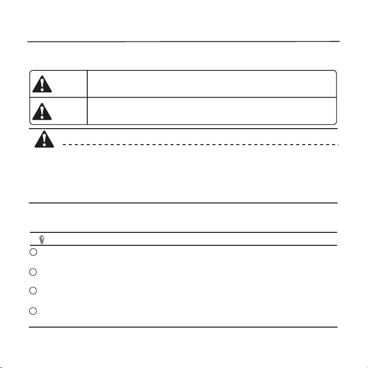
Means improper handling may lead to personal death or severe injury.
Means improper handling may lead to personal injury or property loss.
WARNING
CAUTION
Please entrust the distributor or professionals to install the unit.
Installation by other persons may lead to imperfect installation, electric shock or re.
Adhere to this installation manual.
Imporper installation may lead to electric shock or re.
Reinstallation must be performed by professionals.
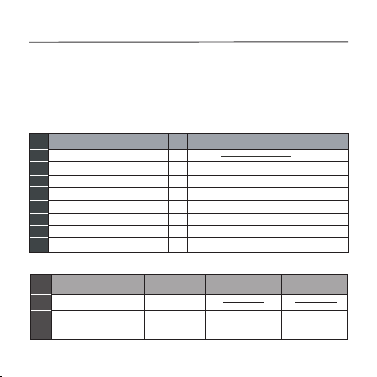
WARNING
Do not install the unit in a place vulnerable to leakage of ammable gases.Once
ammable gases are leaked and left around the wire controller, re may occure.
Do not operate with wet hands or let water enter the wire controller. Otherwise,
electric shock may occur.
The wiring should adapt to the wire controller current. Otherwise, electric leakage or
heating may occur and result in re.
The specied cables shall be applied in the wiring. No external force may be applied
to the terminal. Otherwise, wire cut and heating may occur and result in re.
NOTE
Do not uninstall the unit randomly.
Random uninstalling may lead to abnormal operation, heating or re of the air condition.
1
2
3
4
1. SAFETY PRECAUTION

2
2. INSTALLATION ACCESSORY
Don’t install at the place where cover with heavy oil, vapor or
sulfureted gas, otherwise, this product would be deformed that
would lead to system malfunction.
Select the installation location
Preparation before installation
1. Please conrm that all the following parts you have been supply.
2. Prepare the following assemblies on the site.
1
2
3
4
5
3
2
M4X20 (For Mounting on the Wall)
M4X25 (For Mounting on switch box)
1
2
1
6
7
8
3
2
No. Name Qty. Remarks
Wire controller
Installation and owner’s manual
For Mounting on the Wall
Switch box
Wiring Tube(Insulating
Sleeve and Tightening
Screw)
Qty.(embeded
into wall)
Plastic screw bars
Screws
Wall plugs
For fixing on switch box
(Optional)
No. Name Remarks
Specification
(only for reference)
Screws
1
1
1
Battery
The connection cable
1
1

3
2. INSTALLATION ACCESSORY
WIRED CONTROLLER INSTALLATION PRECAUTION
1. This manual provides the wired controller installation method. Refer
to the wiring diagram in this installation manual to wire the wired
controller with the indoor unit.
2. The wired controller works in a low voltage loop circuit. Do not
connect directly to 208/230V and 460V. Do not wire this kind of wire
into a loop. Wiring clearance between the congured tubes should
range 11.81−19.69 inches (30−50 cm) or above.
3. The shielded wire of the wired controller must be properly grounded.
4. Upon nish the wire controller connection, do not employed
tramegger to detect the insulation.

4
3. INSTALLATION METHOD
Fig 3-1
1.Wired Remote Controller Dimensions
123mm
(4.8”)
120mm
(4.7”) 18.5mm
(0.7”)
83.5mm
(3.3”)
46mm
(1.8”)
62mm
(2.4”)
Fig 3-2
Model A:KJR-120G2/TFBG-E(12V)
Model B:KJR-120G1/TFBG-E(5V)
Model C:KJR-120H2/TFBG-E
120mm
(4.7”)
120mm
(4.7”) 19.3mm
(0.75”)
83.5mm
(3.3”)
43mm
(1.7”)
63mm
(2.5”)

5
3. INSTALLATION METHOD
Fig 3-3
2.Wiring Connection Diagram
red
black
yellow
brown
red
black
yellow
brown
Insert of the
mainboard CN40
Wire controller Indoor unit mainboard
4-Core Shield Cable, the length
is decided by installation
-----------------------------------
-----------------------------------
-----------------------------------
-----------------------------------
Connect the female joint of the wires group from the mainboard
with the male joint of the connective wires group. (See Fig.3-4(A))
Connect the other side of the connective wires group with the male
joint of the wires group leads from the wire controller.(See Fig.3-4(A))
Fig 3-4(A)
Mainboard
4-core shielding wire
3.Wiring figure
Model :KJR-120G2/TFBG-E(12V) &KJR-120H2/TFBG-E
The connection cable
CN40

6
3. INSTALLATION METHOD
Model B:KJR-120G1/TFBG-E(5V) Fig 3-4(B)
Adapter board
Display board
4-core shielding wire
The connection
cable
CN101
Connect the female joint of the wires group from the adapter board
with the male joint of theconnective wires group. Next, connect the
other side of the adapter board with the displayboard. (See Fig.3-4(B))
Connect the other side of the connective wires group with the male
joint of the wires group leads from the wire controller. (See Fig.3-4(B))
Install the Adapter Board and the Display Board on the High Wall
(See the Appendix for instructions).

7
3. INSTALLATION METHOD
Fig 3-5
Fig 3-6
4.Wire controller upper part Remove
Insert a at screwdriver into the slots in the
lower part of the wire controller (2 places).
Remove the upper part of the wire controller
(Fig.3-5)
For surface mounting, fasten the back plate on the wall with the 3
screws (M4x20) and plugs. (Fig.3-6)
Slots
NOTE: The PCB is mounted in the upper part
of the wired controller. Be careful not to
damage the board with the screwdriver.
5. Fasten the wire controller back plate
Back plate
Screws (M4×20)

8
Place the battery in the unit and ensure the positive side of the
battery is in accordance with the polarity markings.(See Fig.3-8)
Set the correct time before operating. Batteries in the wired controller
can maintain the correct time during a power failure. When the power
is restored and the displayed time is not correct, replace the battery.
Fig 3-8
Fig 3-7
3. INSTALLATION METHOD
Switch box
Back plate
For switch box mounting, fasten the back plate on the switch box with
2 screws (M4x25) and fasten it on the wall with 1 screw (M4x20).
(Fig.3-7)
6. Battery installation
Screw (M4×20)
Screws (M4×25)
NOTE: Place on a at surface. Be careful not to distort the wire
controller’s back plate by over−tightening the mounting screws.

9
3. INSTALLATION METHOD
7. Wire the indoor unit
1 from the rear;
2 from the bottom;
3 from the top;
There are three methods:
4. Notch the part for the wiring to pass through with a nipper tool.
PCB
PCB
PCB
1
1
1
2
3

10
Fig 3-9
3. INSTALLATION METHOD
Putty
Putty
Putty
Trap
Trap
Trap
Fig 3-10
IMPORTANT:All the pictures
in this manual are for
illustration purposes only.
Your wire controller may
dier slightly.
8. Reattach the wire controller’s upper part
While adjusting and mounting the upper case, avoid clamping the
wiring during installation. (Fig 3-10)
NOTE: DO NOT allow water to enter the remote control.
Use the trap and putty to seal the wires.

11
4. APPENDIX
INSTALL THE WIRE CONTROLLER KIT
1. Open the front panel.
2. Disconnect the wire from the main controller board.

12
4. APPENDIX
INSTALL THE WIRE CONTROLLER KIT
3. Identify the components. From left to right, the wired controller,
convert board and the display board.
4. Identify connections on the Display Board.
CN201 is the display board connection to the main board wire
(on the display board).

13
4. APPENDIX
INSTALL THE WIRE CONTROLLER KIT
CN101 is the display board connection to the convert board wire
(on the display board).
5. Uninstall the display board from the front panel. Keep the display
board holder.

14
4. APPENDIX
INSTALL THE WIRE CONTROLLER KIT
6. Carefully bend and break o the rectangular section (upper left
section with two diagonal holes) from the display board.
NOTE: Break o the upper left hand rectangle (section with the two
holes marked with a red rectangle).
7. Replace the old display board (for the New Display board provided)
and secure with the clips. To uninstall the clips, push the clips inward.
NOTE: There are 4 clips just above the numeric display (88) which run
the length of the holder.

15
4. APPENDIX
INSTALL THE WIRE CONTROLLER KIT
8. Before assembling mounting back on the Front Panel, remove the
display board’s screen cover.
9. Connect the Wires to the Adaptor Board.
a. Connect the wire coming from the Display board to the Convert
Board (this connection consists of 5 wires).

16
4. APPENDIX
INSTALL THE WIRE CONTROLLER KIT
b. Connect the wire coming from the Wired Remote Controller to
the Convert Board (this connection consists of 4 wires).
10. Once the ports are connected, install the cover.
11. Mount the new display board and convert board to the Front Panel.
12. Connect the wired remote controller to the display board and the
convert board.
13. Connect the wire from the main controller board (see Fig 3-2).
This manual suits for next models
2
Table of contents
Other Lennox Remote Control manuals

Lennox
Lennox Armonia User manual

Lennox
Lennox RG51Q/BGE User manual

Lennox
Lennox LXRCC10 User guide

Lennox
Lennox VRF V0STAT52P-1 User manual

Lennox
Lennox LNIV2610 User manual

Lennox
Lennox e-Lite LV-RC01 User manual

Lennox
Lennox LXRAB10 User manual

Lennox
Lennox LXRCC User manual

Lennox
Lennox 22U52 User manual

Lennox
Lennox M0STAT60Q-1 User manual
Popular Remote Control manuals by other brands

Schartec
Schartec YET045 quick start guide

Centurion
Centurion NOVA instructions

Cotek
Cotek CR Series user manual

Samsung
Samsung SolarCell Remote quick start guide

Hearth & Home
Hearth & Home IntelliFire Touch IFT2-RC450 installation instructions

Viessmann
Viessmann VITOTROL 200 RF Installation and service instructions