Lenord, Bauer PowerDrive-Box GEL 6505 Manual

GEL 6505
Field bus interface for the operation of up to
5 PowerDRIVE positioning drives
Technical information
Version 2014-07
... automates motion.
LENORD
+BAUER
Internet: www.lenord.de
E-Mail: i[email protected]
Phone: +49 208 9963–0
Fax: +49 208 676292
Lenord, Bauer & Co. GmbH
Dohlenstraße 32
46145 Oberhausen, GERMANY
DS22-6505
GEL 6505A: Box for top-hat rail mounting, IP 20 version
GEL 6505B: Box for any other mounting, IP 69K version
General
The PowerDRIVE-Box GEL 6505 is the central unit of the
PowerDRIVE-System from Lenord + Bauer. It is available
in two versions. Up to five PowerDRIVEs can be connec-
teddirectlyusingahybridcablePowerDRIVE-Connect.
The installation of the PowerDRIVE-System is cost-opti-
mised and very compact. The motor power for the position-
ing drives connected is monitored and switched by the
power management in the GEL 6505. The PowerDRIVE-
Boxshouldbesuppliedusinga24VDC/40Apowersup-
ply unit. Communication via common field bus profiles
such as CANopen, PROFIBUS-DP V0/V1, Ethernet/IP or
PROFINET is supported by pluggable modules. With the
aid of the PowerDRIVE-Box GEL 6505 the PowerDRIVEs
can be placed in operation without a higher level control
system.
Features
Configured for up to five PowerDRIVEs
Supply voltage: 24 V DC / 40 A
Separate connection possible for supply of motor power
and for supply of logic power
Field bus modules:
- CANopen
- PROFIBUS-DP
-EtherCAT
- PROFINET-IO
- Ethernet/IP
- sercos Ⅲ(I/O profile)
Protection class IP 20 or IP 69K
Advantages
Compact connection technique
Electronic fuses
Integrated power management
Straightforward commissioning of the PowerDRIVEs
Fields of application
Packaging machines
Food and bottling plants
Wood and plastic working machines
Printing presses and book binding machines
Extensive production plants

Description
2 Lenord, Bauer & Co. GmbH DS22-6505 (2014-07)
System solution
The PowerDRIVE-System consists of three basic compo-
nents: up to 5 compact, fully automated positioning drives
PowerDRIVE, the intelligent decentral communication unit
PowerDRIVE-Box and the hybrid cables PowerDRIVE-
Connect suitable for use in drag chains.
PowerDRIVE-Connect
PowerDRIVE-Box
PowerDRIVE
(5x)
The intelligent PowerDRIVE-Box simplifies commissioning
and allows an efficient integration of the PowerDRIVES in-
to the control of complex production plants. Various field
bus modules are available for the communication with the
central control system.
The PowerDRIVE-Box takes care of the entire power man-
agement for the positioning drives and significantly re-
duces the connection work. The supply of motor power,
supply of logic power and the internal CAN bus communi-
cation between the positioning drives and the Power-
DRIVE-Box are undertaken via the hybrid cable Power-
DRIVE-Connect. Instead of the usual two separate cables
for field bus communication and a third cable to supply
power to the positioning drives, the connection is reduced
to
ONE
hybrid cable suitable for use in drag chains; the lo-
gistics effort for the always identical PowerDRIVEs is mini-
mised. In the maximum configuration with 5 positioning
drives connected, the number of cables can typically be re-
ducedfrom15to5.
The automatic configuration of the PowerDRIVEs after
connection to the PowerDRIVE-BOX and the check on the
system parameters make commissioning straightforward
and quick, even without the central control system connec-
ted.
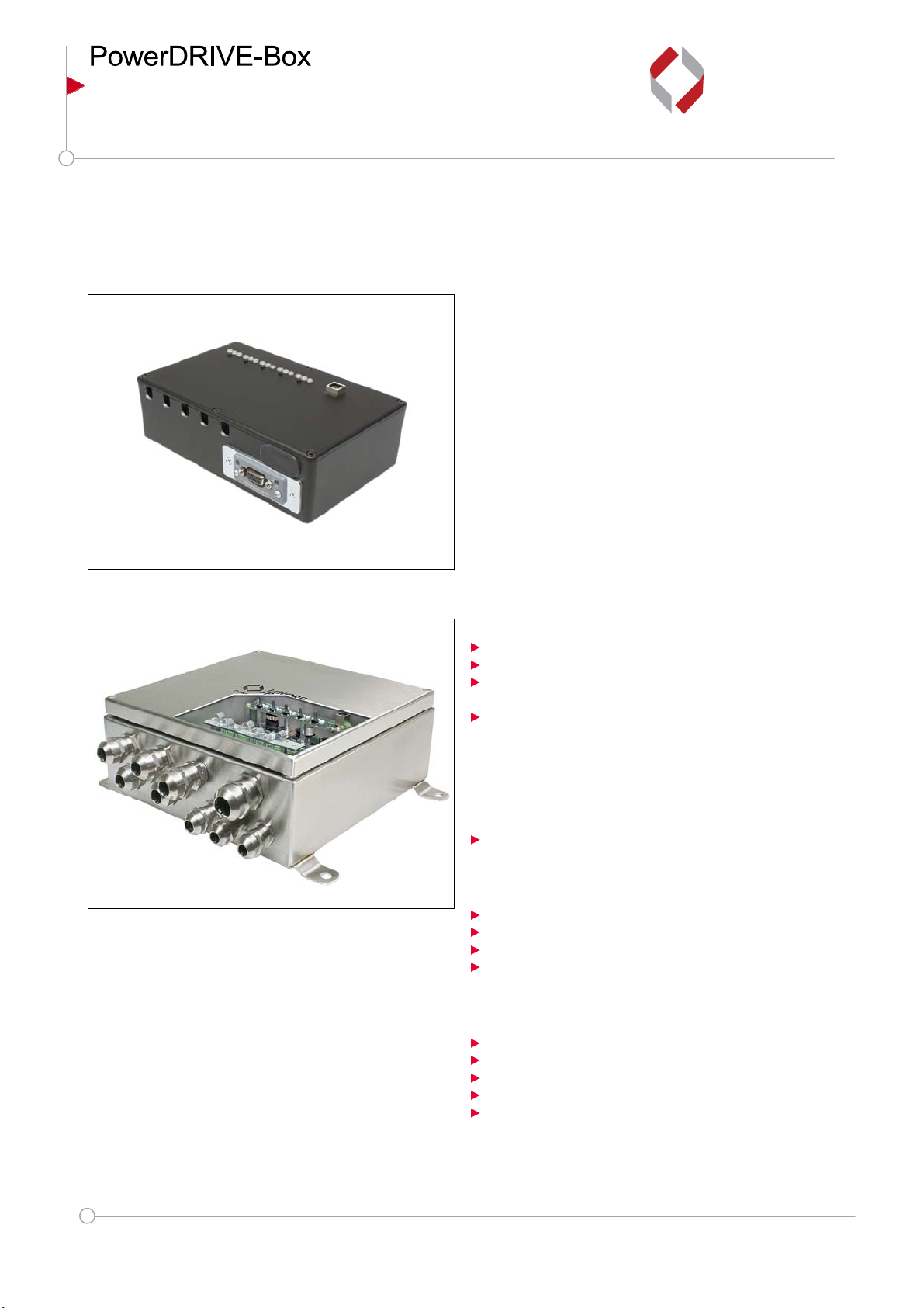
Construction of the PowerDRIVE-Box
GEL 6505A The compact housing of the PowerDRIVE-
Box made of cast aluminium is suitable for
mounting on top hat rails. For testing and
commissioning of each positioning drive,
there are state LEDs and push-buttons on the
front panel.
GEL 6505B The closed housing of stainless steel met
through the cable glands and blanking plugs
the protection class IP 69K. All indication and
connection elements are located inside.
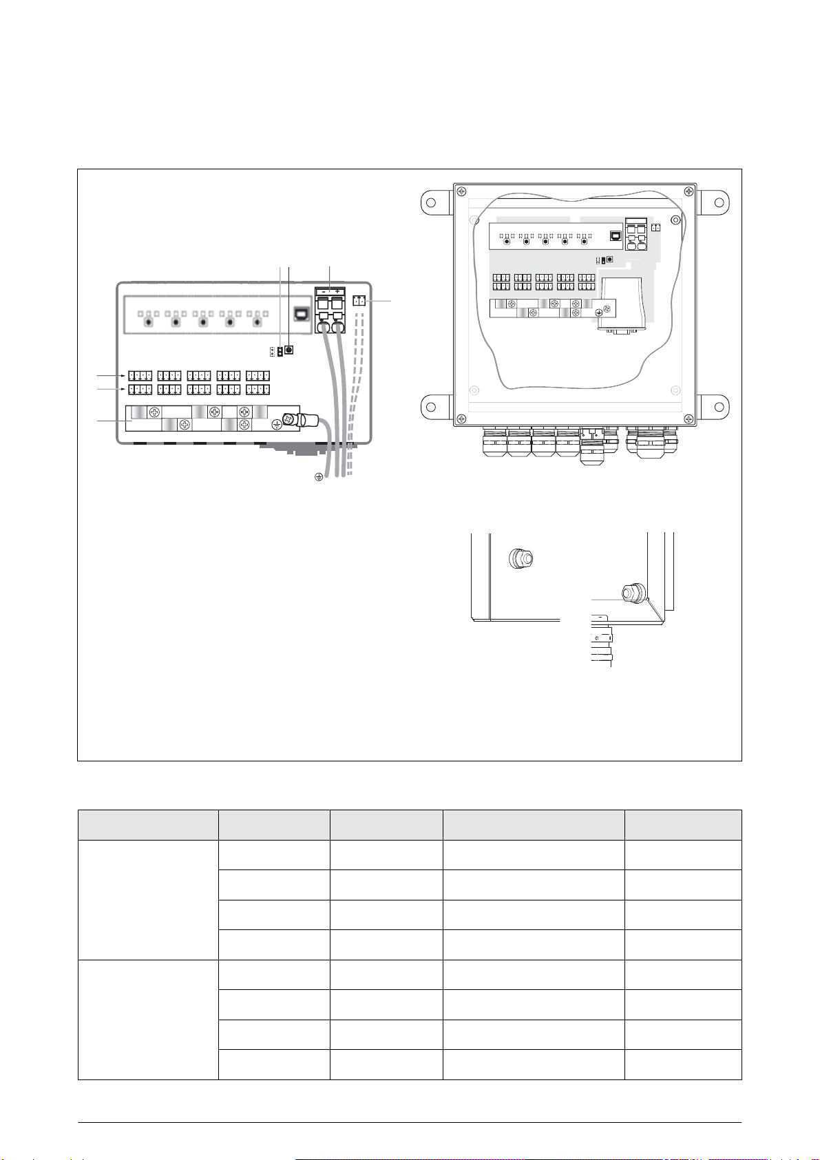
For each positioning drive 3 state LEDs indicate the state
of the power supply and the communication. In case of a
malfunction or during an inspection, the drive voltage and
communication can be switched on or off using push-but-
tons under the LEDs. It is also possible to acknowledge er-
rors and perform a manual reset with the aid of the push-
buttons.
Via a USB interface, the device can be connected to a PC.
Using a terminal program, important parameters can be
read and set. Also, the firmware of the box can be updated
with the aid of a connected PC.
The pluggable fieldbus interface is supplied pre-assembled
as per the type code.
The hybrid cables for the positioning drives are connected
directly to the easily accessible and coded strips using
spring-cage terminals. The hybrid cables are earthed via
an earth rail.
For safe operation, the box provides integrated electronic
fuses. The PowerDRIVE-Box is earthed via an earth cable
and the additional earthing via the top-hat rail or mounting
brackets.
Power is supplied to the PowerDRIVE-Box and positioning
drives either via a common connection or via two separate
connections. Using separate supply, the power of the
drives can be switched off, for example during an “emer-
gency stop”, without interrupting the bus communication. In
this way state monitoring is ensured.
Integrated power management
The maximum power consumption can be programmed via
power management.
It is recommended to use a 24 V DC / 40 A voltage-stabi-
lised power supply that is preferably to be mounted beside
the PowerDRIVE-Box. The supply of power to the motors
and logic for the positioning drives is separate. For require-
ments in accordance with the new Machinery Directive, the
power for the motors can be switched via certified safety
relays in the plant. Nevertheless, continuous state monitor-
ing can be ensured, as the communication via the field bus
is not affected. In this way the drive can be safely shut
down.
PowerDRIVE-Connect
The hybrid cable PowerDRIVE-Connect is designed for
flexible application in drag chains and reaches a permissi-
ble dynamic bending radius of ten times the cable diameter
inatemperaturerangeof-40°Cto+80°C.Thediameter
of the cable is 9.5 mm. The hybrid cable is screened under
the PUR outer sheath. The internal communication cores
are fully insulated and multiply screened.
The positioning drive is available with hybrid cable and
connector. PowerDRIVE and PowerDRIVE-Box can be
quickly and easily connected with pre-assembled field at-
tachable hybrid connection cables .
The M23 quick-acting coupling of the plug connection per-
mits a rapid connection and disconnection of the devices.
In this manner, the positioning drive can be safely isolated
from the power supply within seconds for maintenance and
service work.

Technical data
DS22-6505 (2014-07) Lenord, Bauer & Co. GmbH 3
GEL 6505A GEL 6505B
Electrical data
Power supply Logic: 20 to 30 VDC, 1 A, stabilised
Motors: 24 to 30 VDC (depending on cable
length), max. 40 A (1), stabilised
Fuse protection Internal
Logic (drive): electronic, resetting
Motors: programmable (provide for external
fuse)
Field bus interfaces CANopen, PROFIBUS-DP, PROFINET-IO,
EtherCAT, Ethernet/IP, sercos Ⅲ
Connection technique Spring-cage terminals
Motor power supply: 6 to 10 mm2(2)
Logic power supply: 0.5 to 1.5 mm2
Hybrid cable:
Power supply PowerDRIVE: 0.5/1.5 mm2
Communication PowerDRIVE:
0.14/0.25/0.75 mm2
EMC Electromagnetic immunity: EN 61000-6-1/-2,
EN 61000-4-5 (1 kV surge on DC supply)
Electromagnetic emissions: EN 61000-6-4
Mechanical data
Assembly Top-hat rail Mounting surface
Housing dimensions (W×H×D) 188×120×56 mm 250×250×100 mm
Housing material Aluminium cast Stainless steel 1.4301
Weight 1kg 4.5kg
Protection class (EN 60529) IP 20 IP 69K
Cable glands – 3× M16 (field bus/logic
cable)
5× M20 (hybrid cable,
1× pressure compen-
sation membrane)
1× M25 (power sup-
ply)
Correct clamping of cable diameters – M16: 4.5 to 10 mm
M20: 6 to 13 mm
M25: 9 to 17 mm
Cable gland tightening torque – M16: 1.5 Nm
M20: 3 Nm
M25: 4 Nm
Shock resistance (EN 60068-2-27) 150 ms-2
Vibration resistance (EN 60068-2-6) 50 ms-2,1to100Hz
Ambient data
Operating temperature 0 °C to +60 °C
Condensation Not permitted
(1) Max. permissible constant current of the box. The actual current consumption depends on the number and load of
attached drives. (→Technical information GEL 6110).
(2) Max. tensile force for cable with 6 (10) mm2:80(90)N

Unit overview
4 Lenord, Bauer & Co. GmbH DS22-6505 (2014-07)
View – front panel
1
2
345
6
I II III IV V
GEL 6505A
4321
+ -
12
-
+
Reset
Operation
Upgrade
PowerDRIVE no. 1 2 3 4 5
Communication
Power Supply
GND
+24 V
GND
+24 V
Screen
L
H
GND
GND
+ 24 V
+
Logic
Power
CAN
bk
4
32
1
+
-
1
2
1
-
+
R
eset
O
peration
U
p
g
ra
d
e
P
ower
DRIVE
no.
1
2
3
4
5
C
ommunication
Power
S
upply
G
N
D
+2
4
V
G
N
D
+
24
V
S
creen
L
H
G
N
D
G
N
D
+
24
V
+
Lo
g
i
c
P
owe
r
C
AN
b
k
1
2
34*5
6
I II III IV V
4
GEL 6505B
1 3 LED state indicators for each positioning drive Ito V
2 Push-buttons for the direct control of the PowerDRIVEs
3 Entry or cable glands for hybrid cable PowerDRIVE-Connect from the positioning drives Ito V
4 Field bus interface
4* Fieldbus connection cable gland
5 Cable entry for the supply of power to the power-circuits and logic circuits as well as for the earth
cable gland with pressure compensation for the GEL 6505B
6 USB port
Notes
GEL 6505B Parts 1, 2, 4 and 6 are located inside the housing.
Seal unused cable glands with sealing plugs (eg article no. VB 1246), in order to meet the requirements
on IP 69K.
GEL 6505A Strain relief is ensured by fitting the cover.

Connections and Pin layout
DS22-6505 (2014-07) Lenord, Bauer & Co. GmbH 5
Connections
4321
+ -
12
-
+
4321
-
+
1
2
3
4
567
Internal view of GEL 6505A
4321
+ -
12
-
+
Internal view of GEL 6505B
(construction as GEL 6505A)
1 PowerDRIVE-Connect strips for internal communica-
tion
2 PowerDRIVE-Connect strips for supply (logic and
drive)
3 Earth rail with cable clips for PowerDRIVE-Connect
4 Connection for supply to logic circuits
(in case of separate power supply, optional)
5 Connection for supply to motor circuits
(in case of common power supply also logic circuits)
6 Reset push-button
7 Firmware upgrade jumper
AB
Earting bolts of GEL 6505B
A earthing bolt on the cover
B earthing bolt on the right side wall
Pin layout – hybrid cable PowerDRIVE-Connect
Terminal strip Connection Core colour Cross-section [mm2] Assignment
Supply
1 red 1.5 +24 V drive
2 black 1.5 GND drive
3 red 0.5 +24 V logic
4 black 0.5 GND logic
Internal
communication
1 black 0.14 CAN GND
2 yellow 0.25 CAN_H
3 green 0.25 CAN_L
4 0.75 CAN screen

Dimensional drawing
6 Lenord, Bauer & Co. GmbH DS22-6505 (2014-07)
Dimensional drawing PowerDRIVE-Box
GEL 6505A
8.3
3.4
116
50
56
188
120
170
152
143
18 22 22 22 22
22
44
46

Dimensional drawing
DS22-6505 (2014-07) Lenord, Bauer & Co. GmbH 7
GEL 6505B
6.5
61
41
26
8.5
7
32
18
57 64
34
82 78
95
250 83
210
250
10
296 100
20
Ø 9 (4x)

Type code,
accessories
8 Lenord, Bauer & Co. GmbH DS22-6505 (2014-07)
Type code GEL 6505
Protection class
A
IP20
B
IP67 (only with “Housing” option VA)
Housing
TR
Ground cast aluminium, bare
PB
Powder coated cast aluminium, black
PG
Powder coated cast aluminium, grey RAL 9006 (upon request)
VA
Stainless steel (only for “Protection class” option B)
Plug
1
1 × Sub-D connector (for field bus CO or DP)
2
2 × RJ45 connector (for field bus EC, IP, RT or SE)
Field bus
– –
None
CO
CANopen (based on profile DS 402)
DP
PROFIBUS-DP (based on PROFIDRIVE)
EC
EtherCAT (based on profile DS 402)
IP
Ethernet/IP (based on profile DS 402)
RT
PROFINET-IO (based on PROFIDRIVE)
SC
sercos Ⅲ(I/O profile based on PROFIDRIVE)
Connection accessories
0
No accessories
1
Accessory set for 5 PowerDRIVE positioning drives
GEL 6505
___ ___ _
Connection accessories
The connection accessory set can be selected as an option “
1
” or being ordered separately (item number and scope of
supply see list of accessories).
List of accessories
Description Item no.
Accessory set
for 5 PowerDRIVE positioning drives
1× spring-cage terminal logic supply, 10× spring-cage terminals supply/communication 1× fork
cable lug M4 for cable 4–6 mm2, 1× heat shrink sleeve Ø 13 mm, 1× heat shrink sleeve Ø 6 mm,
1× heat shrink sleeve Ø 3 mm
89070
Sealing plug
for cable gland of PowerDRIVE-Box GEL 6505B VB 1246
Pre-assembled
hybrid cable
, for connection of positioning drive PowerDRIVE to PowerDRIVE-
Box 61BZK(1)
(1) see separate “Technical Information”
Subject to technical modifications and typographical errors.
The latest version can be downloaded at
www.lenord.com
.
Table of contents
Popular Recording Equipment manuals by other brands

Conrad
Conrad 30 42 52 operating instructions

National Instruments
National Instruments FieldPoint FP-1300 user manual

Roland
Roland A-80 Service notes

Osram
Osram e:cue SYMPL bridge Node INFORMATION FOR USE

JAC
JAC JA95-060 Installation and operating manual

Panasonic
Panasonic AYNE2000 - NONLINEAR AV WORKSTA installation manual