Leon Audio Cue Light Master User manual

www.LeonAudio.com.au 01.
16 Channel Cue Light System
Up to 40 programmable Cue Lights
Multiple Cue Lights per channel
2,000m (6500ft) total cable length
Uses a single 1 pair cable
Simultaneous control from two Master Stations
A visual signalling system for theatres that allows
silent cues to be given to actors and technicians
•
•
•
•
•
High reliablity, no RF, no batteries, no Ethernet, routers switches hubs etc

www.LeonAudio.com.au 02.
Power.
36V DC 1.9A
Master Station’s front panel
Master Station’s rear panel
Cue Light Outstation
Quick Start Guide
Using a standard 3 pin XLR microphone cable , c
one or more Outstations to either XLR connector on the
Master Station’s rear panel.
Both XLRs on the Master can be used at the same time.
Both Go and Standby lamps on the Master will light
dimmed once the Outstation has performed a lamp test.
Press a Standby button on the Master Station.
Standby lamps on the Master & Outstation flash.
Press the Outstation’s Acknowledge button
The Standby lamps burn steadily.
Pressing the Acknowledge button when the Standby lamp is
not flashing will light the Call lamp on the Master Station.
Press the Go button
The Go lamps light.
The Standby lamp goes out if it was on.
After 3 seconds the Go lamp flashes.
After a total of 15 seconds, the Go lamp turns itself off.
Trigger cues across multiple channels by the press of a
single Master Group button
Assign channels to Group A or B
When an Outstation is unplugged, the Fault lamp
flashes.
Reset the Fault lamps by pressing both the red and white
buttons on the Master Station.
Or you may prefer to watch the “how to” videos at
onnect
www.LeonAudio.com.au/CueLightVideos
2
5
43
10
5
2
3
4
1
6
8
7
9
10
3
3 7
9
4
4 8
6
1
3 7
•
•
•
•
•
•
•
Quick start guide page 2
1: How to dim all channels at the same time - use group buttons
2: How to clear group assignments by pressing 2 buttons
Occasionally asked questions:
A: Wrong address
B: An outstation is not as bright as all the others

www.LeonAudio.com.au 03.
Index Quick start Guide
The Cue Light Components
16 Channel Master Station. QLM16 Mk4
Dual Master Stations
Cue Light Outstation types and configuration
Cue Light Outstations
Standard Outstation. QLS Mk4
eeper. QLS-B Mk4
Small Footprint Cue Light. QLS-SM Mk4
Multiple Outstations per channel
Relay Outstation. QLR Mk4
Sensor Outstation. QTS Mk4
Work-Light Outstation. QWL-xx Mk4
Changing an Outstation’s channel
Outstation Cables
What’s the cable limit?
More than 16 channels
Linking multiple Master Stations
Master Station’s Configuration Editor
Alternate Button Overlays
Starting the Configuration Editor
Opening & closing files
Restoring previously saved files
Cue Light Outstation options
Master Station options
Relay Outstation options
Sensor Outstation Options
PCinterface QL-PCi Mk4
Work-Light Outstation QWL-xx Mk4
Standard Outstation with b
Small Footprint with beeper. QLS-SM Mk4
2
4
6
7
8
14
16
17
21
22
25
28
29
30
38
39
40
41
42
43
44
45
48
50
53
Diagnostics
System design suggestions.
Why not use bigger buttons?
Specifications
Warranty
54
55
56
57
60

www.LeonAudio.com.au
Cue Light Components
Cue Light Beeper
Model QLS-B Mk4
Outstation with
16 channel digital Cue Light Master can be used with
any number of Cue Light Outstations from 1 to 40.
Any number of Outstations (up to the maximum of 40) can
be connected to any channel.
Up to 6 Master Stations can be linked for larger systems.
Dual Masters can be used on the same wiring universe.
Can be controlled from a PC running show control software.
5 types of Outstation including Relay and Sensor versions.
programmable with up to 17 options.
Outstations can be wired using daisy chain, star and/or loop
wiring topologies on a single circuit using 3 pin XLR
microphone cable.
Total cable length can be greater than 2,000m (6,500 feet).
Powered from a universal 90/264V 50/60Hz external power
supply.
Station
Each individual channel
20mm Go and Standby LED lamps are b
and dimmable.
Standby lamp programmable to red or yellow on a channel
by channel basis.
Non-standard lamp colours available to special order.
Backlit Acknowledge button can also signal the Master
Station.
Eavesdrop mode switch enables the use of multiple
Outstations per channel.
17 programmable options for each individual Outstation.
3/8" microphone stand mount and 10mm mounting hole for
hook clamp.
right, wide angle
Cue Light Master Station.
Standard Cue Light Outstation
Model QLS Mk4
As per the Standard Outstation, but with an inbuilt beeper.
The beeper is triggered by the Beep button on the Master
Station and/or programmable Beep-on-Go option.
It can be used as a Standard Outstation (without beeps) as it
only beeps when specifically commanded to do so.
Cue Light Outstation with Beeper. QLS-B Mk4
Details on page 17
04.
All Outstations are available individually.
Cue Light Outstation QLS Mk4
Details on page 17
Cue Light Master Station QLM16 Mk4
Details on page 8
•
•
•
•
•
•
•
•
•
•
•
•
•
•
•
•
•
•
•

www.LeonAudio.com.au
Cue Light Components (continued)
All Outstations are individually.available
•
Relay Outstation
This Outstation has two relays with changeover contacts
which allows for direct control of other circuits such as
smoke machines, door bells and stage telephones etc.
The relays are controlled by the Go and Standby buttons on
the Master Station.
Connection to the voltage free relay contacts is via Phoenix
compatible connectors.
There is provision for an external Acknowledge button.
10 programmable options for each individual Outstation.
It can function as a Standard Outstation although the Go
and Standby lamps are only 3mm in diameter.
Cue Light/Latching/Momentary operating modes are
selectable.
Eavesdrop mode switch enables the use of multiple
Outstations per channel.
Relay Outstation QLR Mk4
Details on page 22
•
•
•
•
•
•
Useful where space is limited such as on lectern tops.
20mm Go and Standby LED lamps are bright, wide angle
and dimmable.
Standby lamp programmable to red or yellow on a channel
by channel basis.
Backlit Acknowledge button can also signal the Master
Station.
16 programmable options for each individual Outstation.
It has no Eavesdrop mode switch.
Permanently attached 1m Canare cable fitted with a 3 pin
male XLR.
Small Footprint Cue Light QLS-SM Mk4
Details on page 17
•
•
•
•
•
•
•
05.
Small Footprint Cue Light Beeper
Model QLS-SM-B Mk4
with
Small Footprint Cue Light
Model QLS-SM Mk4
As per the Standard Outstation, but with an inbuilt beeper.
The beeper is triggered by the Beep button on the Master
Station and/or programmable Beep-on-Go option.
It can be used as a Standard Outstation (without beeps) as
it only beeps when specifically commanded to do so.
Small Footprint Cue Light with Beeper.
Details on page 17
•
•
•
QLS-SM-B Mk4

www.LeonAudio.com.au
Connects between the Master Station and a PC running
party show control software to provide remote control for up
to 6 Master Stations via RS232 or RS485.
Allows control from a touch screen or show control script.
3rd
A separate PDF detailing the PCinterface QL-PCi Mk4 can
be found here www.LeonAudio.com.au/PCinterface.pdf
Contact Sensor
Allows monitoring of remote switch contacts such as used
on a theatrical trap door lock.
Sensor have a dedicated display on the Master
Station.
Normally open or closed single pole contact required.
Selectable End Of Line Resistor detects opens & shorts in
the local switch wiring.
Three programmable options for each individual
Outstations
Sensor
Outstation.
RS232/RS485
Computer interface
Contact Sensor
Details on page 25
PCinterface
•
•
•
•
•
•
•
•
06.
Cue Light Components (continued)
QTS Mk4 QL-PCi Mk4
All Outstations are individually.available

www.LeonAudio.com.au
Coming Soon
Ethernet bridge.
Repeater/Splitter with 3 ports.
2,000m of cable on each port. (6,000m in total)
Master Station and Outstations can connect
anywhere on any port.
Supports up to 120 Outstations.
•
•
07.
Cue Light Components (continued)
Work-Light
Powered by the Cue Light system, it connects just like a
standard Cue Light Outstation.
Reduced Work-Light set-up time.
Battery backing the Master Station provides continuous
backstage/understage lighting in case of loss of mains.
The Work-Light can be turned on/off by a channel on the
Master Station or it can be set to be on all the time, saving
resources on the Master.
Independent 10 step dimmer.
Typically 20+ Work-Lights can be connected to a system.
(Dependent on how many Cue Light Outstations are connected)
600mW Work-Light
Details on page 28
•
•
•
•
QWL-BL Mk4 (Blue LEDs)
QWL-WH Mk4 (White LEDs)
•

www.LeonAudio.com.au
16 Channel Master Station QLM16 Mk4
The Cue Light system consists of a Master Station and any
number of Cue Light Outstations from 1 to a maximum of 40.
Cue Light Outstations have an Eavesdrop mode which
allows any number of Outstations to be assigned to the
same channel (up to the system’s maximum of 40).
The Master Station can be at connected at any point in the
wiring universe. This allows the Master Station to be easily
moved from any node to any other node on the wiring such
as from prompt corner to a production desk in the auditorium
during rehearsals.
Two Master Stations can be connected to the same wiring
universe allowing for dual control of 16 channels.
The wiring between a Master Station and its Outstations is
known as a wiring universe. A universe supports a
maximum of 16 channels. With multiple Outstations per
channel, there may be up to 40 Outstations connected to
these 16 channels.
Up to 6 Master Stations can be linked for larger systems.
Each Master Station must have its own wiring universe of
16 channels.
The digitally addressed Cue Light Outstations are
connected using a single circuit of 3 pin XLR microphone
cables although screened data cable is preferable.
CAT5/6 cable may be used.
Outstations may be connected using either daisy chain, star
and/or loop wiring topologies. The Master Station provides
power to all Outstations over this same cable.
Cable faults are reported as soon as they happen as
Outstations are in continuous communication with the
Master Station.
A Short lamp indicates short circuits in the external wiring
to the Outstations. External wiring is protected by an
electronic current limiter which is backed up by a
.
A white designation strip runs beneath all channels.
self
resetting fuse
08.

www.LeonAudio.com.au
16 Channel Master Station (continued)
3
2
1
Go and Standby buttons
The illuminated
This is known as positive
monitoring. It is
Go and Standby buttons on the Master
Station light dim once an Outstation is connected and has
performed a lamp test. These 2 buttons are used to send
cues to the Cue Light Outstations.
The illuminated Go and Standby buttons are driven by data
returned from the Outstations and light brightly in response
to a Go or Standby cue.
not just a local indication that a button has
been pressed.
2
1
Eavesdrop Outstations
On any channel, set only one Outstation to Normal Mode.
This Outstation will send return monitoring to the Master
Station for driving the Go and Standby lamps
All additional Outstations assigned to that same channel
must be set to Eavesdrop Mode.
They can however, send Call signals. (see the following
page)
See the section on Multiple Outstations per channel
(page 21) for more details on Eavesdrop Mode.
These additional Outstations respond to commands from
the Master Station but send no return monitoring.
2
1
09.
The Contact Sensor Outstation QTS Mk4 allows remote
monitoring of voltage free switch contacts such as used on
a theatrical trap door’s lock.
Sensor units 1-4 have a dedicated display on the Master
Station
Sensor units 5-16 use channels 5-16 on the Master Station.
Other Outstations can not share a channel with a Sensor
Outstation.
3
Contact Sensor Outstations

www.LeonAudio.com.au
Each channel has a blue Call lamp which enables an
Outstation to signal the Master Station.
An Outstation’s Acknowledge button has 2 functions.
If a Standby cue is waiting to be acknowledged (Standby
lamps flashing), pressing the Acknowledge button will cause
the Standby lamps to burn steadily.
Pressing the Acknowledge button at any other time will light
the blue Call lamp on the Master Station.
The Call lamps can be disabled as well as set to flash or
light steadily on a channel by channel basis. These changes
are made via the Master Station’s Configuration Editor.
(see page 41)
While Outstations set to Eavesdrop Mode do not send
return monitoring to the Master, they do send Call signals.
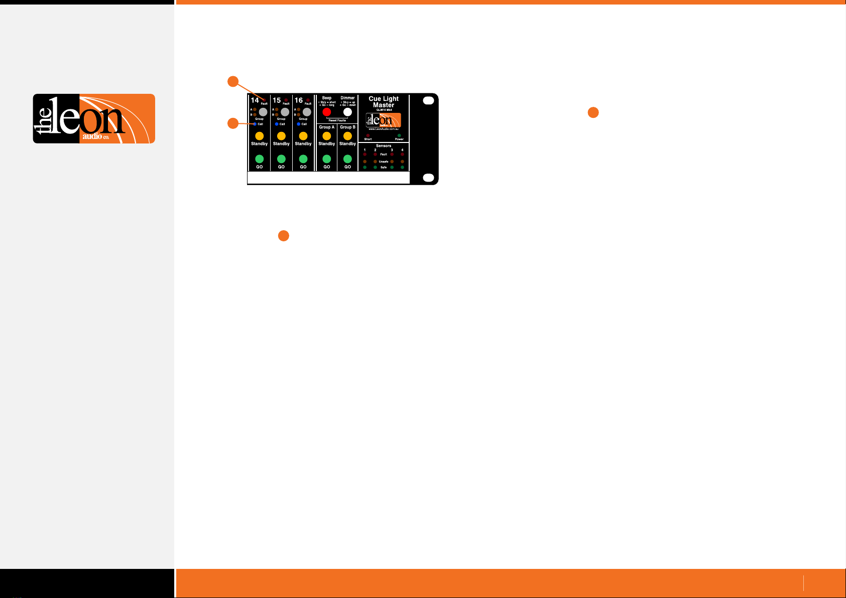
Call lamps
•
•
•
Fault lamps
•
•
A red Fault lamp at the top of each channel indicates when
an Outstation is not communicating with the Master Station.
This could be due to an unplugged Outstation or a cable
fault.
The Fault lamp has 3 states. On, Off and Flashing.
The Fault lamp is off when a channel is unused (no
Outstation connected). Go and Standby buttons will also be
off. The Fault lamp is also off when an Outstation is
connected but in this case the Go and Standby buttons will
light dimmed.
The Fault lamp is lit steadily if a channel has an Outstation
connected in Eavesdrop Mode but no Outstation in
Normal Mode.
The Eavesdrop Mode Outstation will still respond to Go
and Standby cues but the Go and Standby buttons on the
Master Station will not light as there is no return monitoring
from Outstations in Eavesdrop Mode.
The Fault lamp flashes when all Outstations on that channel
are unplugged.
Flashing Fault lamps can be reset by pressing both the
white and red buttons on the Master Station.
The Master Station and Outstations are in continuous
communication with each other, enabling prompt detection
of cable faults or disconnected Outstations.
1
2
1
2
10.
16 Channel Master Station (continued)

www.LeonAudio.com.au
Parallel XLR
connectors for
Outstations
Power.
36V DC 1.9A
Parallel Expansion Ports
for PCinterface and
the linking of Masters
Master’s Mode switch.
Used when 2 Masters
are connected
12
43
Group buttons
The group feature allows cues across multiple channels to
be triggered by the press of a single button.
Any channel can be assigned to one of two Group Master
buttons Group A and Group B
The group assignment for each channel is controlled by the
grey Group button and two associated amber lamps
Pressing a grey Group button cycles through four possible
group assignments: A, B, A+B and none.
Pressing either of the Group Master Go or Standby buttons
is exactly the same as pressing the corresponding Go or
Standby button on any channel that has been assigned to
that Group Master.
The channel's Go and Standby buttons still remain fully
operational independent of any group assignment.
The status of each channel’s Group assignment is saved in
EEPROM memory and is restored when the Master Station
is powered up.
1
2
43
11.
Linking Multiple Master stations
5
To quickly clear Group assignments across multiple
channels, press and hold any two grey Group buttons for
0.5 seconds. All channels between (and including) those two
grey buttons will have their Group assignments set to off.
16 Channel Master Station (continued)
Master Station’s rear panel
When multiple Master Stations are used, the 4 Group
Master buttons can be linked across the Masters via
Expansion Ports on the Masters’ rear panels.
Up to 6 Master Stations can be linked.
on any
linked Master Station, will electronically press the
corresponding Group Master button on all linked Master
Stations.
For more details see Linking multiple Master Stations on
page 39.
Pressing any of the four Group Master buttons
This allows cues across multiple Master Stations
to be triggered by the press of a single button.
43
5

www.LeonAudio.com.au
Beep button
Dimmer button
The Cue Light Outstation lamps can be dimmed in five
steps from 100% down to 5%.
Press and hold the white Dimmer button on the Master
Station. Use the Standby button to increase intensity or the
Go button to decrease intensity.
Once 5% or 100% is reached, further presses are ignored.
Four presses of the Standby button will set an Outstation to
100% irrespective of its initial setting. The Dimmer button
can also be used in conjunction with the Group Master
buttons.
The Go and Standby lamps on the selected Outstation flash
alternately as the intensity is adjusted.
The intensity can also be adjusted from an Outstation.
Press and hold the dimmer button on the Master Station.
Pressing the Acknowledge button on an Outstation starts
the Go and Standby lamps flashing alternately. Subsequent
presses of the Acknowledge button increase the intensity by
1 step. When 100% is reached, it rolls back to 5%. The
lamps flash faster when at 100%.
The dimmer settings for each channel are saved in the
Master’s memory and are restored when the Master Station
is powered up.
The red Beep button works like a shift key in conjunction
with a channel’s Go and Standby buttons.
The Beep function requires the Beeper Outstation (Model
QLS-B or QLS-SM-B).
The QLS-B Outstation functions just like a standard
outstation when the Master’s beep button isn’t pressed.
The beeper can be triggered to emit either a very short
beep (which sounds like a click), or beep for as long as the
button is pressed, up to a maximum of one second.
12.
12
1
2
The Short lamp indicates short circuits on the external XLR
wiring. Fault current is electronically limited to approximately
1.6 amps.
If the short is maintained for more than 400mS, the power
supply enters a hiccup mode where power to the
Outstations is turned off and reapplied once every few
seconds until the fault is cleared.
If the short is persistent, the period before reapplying power
increases from 2 seconds to 8 seconds.
Short lamp 3
3
The beep is accompanied by flashing of the Standby lamp
on the triggered Outstation(s). The Beep button can also be
used in conjunction with the Group Master buttons.
The beep function can be disabled on a channel by channel
basis via the Master’s Configuration Editor. (see page 41)
The Beep command is ignored by Outstations not fitted with
a beeper.
Beep button + Standby button = very short beep.
Beep button + Go button = long beep.
16 Channel Master Station (continued)
Multiple channels can be dimmed simultaneously by
assigning channels to one of the 2 Groups and then
using that Group’s Master Go and Standby buttons to
increase or decrease the dimmer intensity.
Tip:

www.LeonAudio.com.au
Parallel XLR
connectors for
Outstations
Power.
36V DC 1.9A
Parallel Expansion Ports
for PCinterface and
the linking of Masters
Master’s Mode switch.
Used when 2 Masters
are connected
Expansion Port wiring
(looking at the socket on the rear of the Master)
Pins 1&2: Ground
Pins 3 & 4: RS485 data
Pins 5&6: +30V power
1
Expansion Port
An Expansion Port consisting of
connectors allows for linking of multiple Master Stations
(see page 11) and also for connection of the PCinterface
unit .
The cable is of the 6 core flat telephone type. Suitable
cables are supplied with the PCinterface and multiple
Master Station purchases.
These cables are intended to be short patch leads because
they are unscreened and untwisted, however, lengths up to
100m (300 ft) will work.
two parallel RJ12
(see page 6)
RJ12 cables with only 4 of the 6 pins wired can also be
used. (pins 1 & 6 not wired)
1
2
3
The Master Station is powered from an external AC adaptor
rated at 36V DC and 1.9 amps.
Input to the adaptor is 90 to 264 volts 50/60Hz.
The Master Station provides power to all Outstations via the
interconnecting 3 pin XLR cables.
The Master Station can be powered from a supply as low as
24 volts DC although the cable length to the Outstations
may need to be reduced as there are less volts available to
overcome losses in the interconnecting cables.
Power Connector
RJ12
654321
Master Mode Switch
Master’s Mode switch
Master
Mode
Main
Slave
Main: Single or 1st Master
Slave: 2nd Master
When two Master Stations are connected to the same wiring
universe for dual control of the same 16 channels, set the
Master Mode switch on one to Main and to
Slave on the second Master Station.
The configuration settings stored in the Main Master Station
will be those used to run the Cue Lights.
These configuration settings will also be copied across to the
Slave Master so that either Master can then run the show.
Master Station
If only one Master Station is connected, set the mode switch
to the Main position.
13.
3
2
16 Channel Master Station (continued)
Master Station’s rear panel

www.LeonAudio.com.au
4
Using standard 3 pin XLR microphone cables , c
one or more Outstations to either XLR connector on
Master Station A’s rear panel.
Connect Master Station ‘B’ to the Cue Light wiring
The Masters can connect anywhere to the Cue Light wiring.
There is no specific order in which they need to be
connected. The drawing above is just an example.
onnect
1
16 Channel Master Station (continued)
Quick Start Guide for Dual Master Stations
4
•
•
2
3
Master
Station ‘A’
Master
Mode
Main
Slave
Two Master Stations can be connected to the same Cue
Light wiring universe allowing for control of 16 channels
from both Master Stations at the same time.
Typical applications include using a second Master Station
when a stage manager’s sight lines are blocked and also at
the production desk in the auditorium during rehearsals.
Power
36V DC
Master
Mode
Main
Slave
Add additional Outstations if required
Both XLRs on both Masters can be used at the same time.
Set the Master Mode switch on Master ‘B’ to Slave
Connect a mains power supply to either Master Station
Only one power supply is required.
Set the Master Mode switch on Master ‘A’ to Main
•
•
•
12 3 4
•
5
67
5
6
7
Master
Station ‘B’
14.

www.LeonAudio.com.au
Power
Only one of the two Master Stations needs to have its mains
power supply connected. It does not matter which one. The
other Master is powered from the Cue Light network wiring
just as Outstations are powered.
It is possible to connect a mains power supply to each
Master. This will however create an earth loop because
each power supply is connected to mains earth. While this
earth loop will not usually cause any problems, please be
aware that just as an earth loop can cause hum in an
analog audio circuit, there is also a small chance it may
cause data corruption in a digital circuit. To avoid earth
loops, use a single mains power supply.
16 Channel Master Station (continued)
Dual Master Stations
The Slave Master is in the stage manager’s console.
The Main Master is at the production desk in the
auditorium during rehearsals.
Configuration changes are made at the production
desk’s Main Master. These changes are copied in the
background to the stage manager’s Slave Master.
When rehearsals are complete, the Main Master is
disconnected and the Cue Lights are controlled by the
Slave Master.
Typical application
Master Mode (Main/Slave) switch.
The Master Mode switch is on the rear panel. One Master
must be set to Main and the other Master set to Slave.
The Master Station that is set to Main will provide the
configuration data for the system.
Master’s Mode switch
Master
Mode
Main
Slave
Any configuration changes must be made via the Main
Master Station. The configuration data is copied
automatically in the background from the Main to Slave
Master, allowing the Slave Master to configure and control
the Cue Light Outstations directly should the Main Master
be disconnected.
If both Master Mode switches should be set to the same
position, a visual indication is given on both Master Stations
by alternately flashing all the lamps on channels 1-8 with
those on channels 9-16.
When a Master Station is running solo, the Mode switch
position does not matter.
The configuration settings stored in the Slave Master will be
overwritten by the configuration settings sent from the Main
Master. If there are any configuration settings you wish to
save in the Slave Master, copy them to one of the four user
memory locations in the Slave before connecting it to the
Main Master.
Use with the PCinterface
The optional PCinterface must be connected to the Main
Master Station.
15.
Upgrade
All 16 channel Cue Light systems can be upgraded to
support Dual Master operation if they do not currently
support it.

www.LeonAudio.com.au 16.
There are currently 3 main different types of Outstation that
can be connected to the Cue Light Master Station.
Standard Outstation (QLS MK4)
Variants: Beeper (QLS-B Mk4)
Small Footprint (QLS-SM Mk4)
Relay Outstation (QLR Mk4)
Sensor Outstation (QTS Mk4)
There are a number of options that can be configured for
each type of Outstation. Details of these options can be
found in the following pages describing each type of
Outstation. All options can be changed using the Master
Station’s Configuration Editor. (see page 41)
The Relay Outstation (QLR Mk4) and Sensor Outstation
(QTS Mk4) also allow their configuration to be changed from
their front panels. Any configuration changes made this way
are sent to the Master Station and saved in the Master’s
memory for recall next time the system is powered up.
The Master Station has seven files that can be recalled by
the user. There are two Factory Default , one
Installer’s Default and four User
The configuration settings stay with the channel and do not
follow the Outstation. If an Outstation is re-addressed to a
different channel, it will take on the configuration settings of
the new channel. When an additional Outstation (in
Eavesdrop Mode) is added to a channel it will take on the
configuration settings assigned to that channel.
Standard with
Small with Beeper (QLS-SM-B Mk4)
Any of the three Outstation types can be connected to any
channel. The Master Station stores configuration (option)
settings for each type of Outstation for each channel. When
an Outstation is connected, the configuration data for that
specific type of Outstation is used to configure that channel.
When an Outstation is swapped for a different type, the
configuration data for the newly connected type of
Outstation is used by the Master to reconfigure that channel.
files
file files.
Outstation types and configuration
Different Types: Same channel, same timeOutstation Configuration
•
•
•
Different types of Outstation (QLS, QLR or QTS) can be
connected to the same channel at the same time but only
one type will be operational.
The first Outstation type to be connected will become
operational. Other Outstation type(s) added later will be
non-operational until the first (operational) Outstation is
unplugged. This situation can occur during scene changes.
When 2 or more different types of Outstation are connected
at power up, the type with the highest precedence will
become operational. Types with lower precedence will be
non-operational until the operational Outstation is
unplugged.
The order of precedence is :-
Highest: Standard Outstation ( QLS
Relay Outstation QLR
Lowest: Sensor Outstation QTS.
or Small Footprint)
On all types of Outstations, the Acknowledge button's
back-light will flash.
Exceptions:
Sensor Outstation (QTS Mk4)
The three yellow buttons will flash.
Worklight (QWL)
The dimmer button's back-light will flash.
Indication of non-operational Outstation

www.LeonAudio.com.au
Cue Light Outstations
QLS Mk4
QLS-B Mk4
QLS-SM Mk4
QLS-SM-B Mk4
Standard
Standard + beeper
Small Footprint
Small Footprint + beeper
The Beeper Outstations can be used as a Standard
Outstation. They only beep when the red button on
the Master Station is pressed in conjunction with the Go or
Standby button on the required channel.
They can be made to beep whether a cue is active or not.
Beeper Outstations can also be programmed to beep when
ever a Go cue is received. See Beep-On-Go on page 20.
Beep
Beep button + Standby button = very short beep.
Beep button + Go button = long beep.
17.
Standard Cue Light Outstation QLS Mk4
Typical Operation (with factory default settings)
•
•
•
It is not necessary to give a Standby cue before giving a Go
cue.
The Go or Standby lamps can be turned off at any time by
pressing their respective buttons a second time.
Multiple Go cues are done by using the Go button only.
Press Go to turn the Go lamp on, press it again to turn it off.
The Go lamp is also programmable (on a per channel basis)
between latching or non-latching (momentary acting) to
allow for even faster cueing. Op
Go and Standby cues can be given or cancelled at any
time regardless of any previous cue state.
tions can be changed using
the Master Station’s Configuration Editor. (see page 41)
Outstation with Beeper QLS-B Mk4
Small Footprint Cue Light QLS-SM Mk4
Press a Standby button on the Master Station.
Standby lamps on both the Master Station
and Cue Light Outstation flash.
Press the Outstation’s Acknowledge button.
The Standby lamps burn steadily.
Press a Go button on the Master Station.
The Go lamps light. The Standby lamp goes
out if it was on.
After 3 seconds the Go lamp flashes.
After 15 seconds, the Go lamp turns off.
See the “how to” videos at
www.LeonAudio.com.au/CueLightVideos
Small Footprint with Beeper QLS-SM-B Mk4

www.LeonAudio.com.au
Anywhere from 1 to 40 Outstations can be connected to the
Master Station. Any number of these Outstations can be
connected to any channel.
20mm Go and Standby lamps are bright, wide angle and
dimmable in 5 steps from 100% down to 5%.
The Go and Standby lamps consist of four LEDs for each
colour. The LEDs are wired in 2 circuits with two LEDs per
circuit to provide redundancy should any of the LEDs fail.
The Acknowledge button is back lit so you can find it in the
dark. The back-light only comes on when error free
communication is established with the Master Station. The
back-light winks slowly if data is lost as can happen if the 2
data conductors (XLR pins 2 & 3) on the interconnecting
cables are shorted together.
Any Outstation can Call the Master Station. An Outstation’s
Acknowledge button has 2 functions. If a Standby cue is
waiting to be acknowledged (Standby lamp flashing),
pressing the Acknowledge button will cause the Standby
lamps to burn steadily. Pressing the Acknowledge button at
any other time will light the Call lamp on the Master Station.
The address of any Outstation can be changed in a few
seconds without the use of any tools or fiddly DIP switches.
See Changing an Outstation’s channel (see page 28)
Outstations may be connected using either daisy chain, star
and/or loop wiring topologies. Outstations can be wired up
in any order. Outstation #2 does not have to follow #1 in a
daisy chain.
Multiple Outstations can be used on the same channel by
setting additional Outstations to Eavesdrop Mode.
See Multiple Outstations per channel (see page 21)
Outstations can be added or removed while the power is on.
Flush mounted Acknowledge button, Go and Standby lamps
are very difficult to break or shear off.
18.
Standard Outstations (continued)
The 2mm steel outer case has a total of 6 mounting holes
including a 10mm hole for attaching a hook clamp.
A 3/8" microphone stand mount is at the centre of the rear
cover. When mounted to a microphone stand with the front
of the Outstation facing the ceiling, the Outstation can be
viewed from 360 degrees.
The Outstation data is balanced and uses transformer
isolated RS485. (RS485 is what DMX uses.)
The data uses a Group Encoding scheme with digital
FM modulation for excellent noise immunity and error
detection.
Data is slew rate limited to reduce radiated electrical
noise to a minimum.
Outstations are powered by the Phantom Power
principle where power is sent down the data pair with a
ground return.
Technical note
QLS rear cover showing mounting points.
5 x 6.35mm (1/4")
3/8" microphone
stand thread
10mm (3/8") for
hook clamp
Hook clamp (not supplied)

www.LeonAudio.com.au
The following options can be programmed
individually for each channel from the Master Station.
To change any of these settings, see the Master’s
Configuration Editor on page 41.
Outstation
These 17 options can be combined in 96,304 different ways
for each channel. Hopefully there is a combination that suits
any special applications that may arise. Please let us know
if there are any options that you would like but are not
provided.
•
•
Non-standard Go & S/by colours available to special order.
Selectable between red and yellow (default)
Default setting is to flash.
Some users prefer a non-flashing standby lamp.
The Outstation’s standby lamp can be set to flash or not
independently of the standby lamp on the Master Station.
To indicate an acknowledged cue on the Outstation, the
Outstation can be set to DIM on Acknowledge if required.
Standby Flash on Outstation
Standby Colour
•
Default setting is to flash.
If the Outstation’s standby lamp is set to not flash, it is
desirable to have the Master Station’s lamp flash so that an
indication of an Acknowledged cue can be seen.
Some applications use the Outstations to indicate a
safe/unsafe condition. In this situation the standby lamps on
both the Master and Outstation can be set to not flash.
Default setting is to latch.
If set to unlatched (momentary action), the Standby lamp will
only be lit for as long as the Master Station’s Standby button
is pressed.
Default setting is not to dim.
When an Outstation’s Standby lamp is set to not flash, the
Outstation can be set to dim its Standby lamp to indicate an
acknowledged cue.
Default setting is not to flicker.
As an aid for colour blind users, the Go lamp can be set to
flicker instead of burning steadily.
The flicker rate is approximately 30Hz.
Default setting is to time out after 15 seconds.
Once a Go button on the Master has been pressed, the cue
will cancel itself after 15 seconds allowing the stage manager
to attend to other duties. It can be set to not time out and will
stay on until either the Go or Standby button is pressed.
Default setting is to flash.
Once a Go button on the Master Station has been pressed,
the Go lamp will initially burn steadily but will flash after 3
seconds. It can be set to not flash and will burn steadily until
it times out or is cancelled.
The default time-out period is 15 seconds but is user
adjustable from 1 to 16 seconds. See page 49.
Standby Flash on Master
•
•
•
•
•
Standby Latches
Standby Dim on Acknowledge
Go lamp flickers
Go lamp times out
Go lamp flashes
19.
Standard Outstations (continued)
S/by colour
S/by Flash on Master
S/by Flash on Outstation
S/by latches
S/by Dim on ACK
Go Flickers
Go times out
Go flashes
Go latches
Go & S/by interlocked
Call enabled
Call lashes
ACK button back-light
Beeper
Beep-on-Go
Dimmer
Change colour on ACK
lamp
lamp f
Factory
Default
Yellow
Flashes
Flashes
Latches
No
Steady
Times out
Flashes
Latches
Interlocked
Enabled
Flashes
On
Enabled
Silent
100%
No change
Red
Steady
Steady
Momentary
Dims on ACK
Flickers
Stays on
Steady
Momentary
Independent
Call lamp off
Steady
Off
Disabled
Beeps (4 choices)
5-100% in 5 steps
Change colour
User Selectable
Option
Options
Cue Light options for the following Outstation types:
Standard (QLS), Beeper (QLS-B)
Small (QLS-SM) and
Standard with
Small with beeper (QLS-SM-B)
1
2
3
4
5
6
7
8
9
10
11
12
13
14
15
16
17
Beeper and Beep-On-Go options only apply when a Beeper
Outstation (QLS-B or QLS-SM-B) is connected to that channel.
Outstations without a beeper ignore the beeper settings.

www.LeonAudio.com.au
Default setting is to be lit.
The Acknowledge button’s back-light can be turned off.
One well known circus uses the Outstations to indicate the
safety status of acrobatic equipment. In this case the back-
light is turned off to improve the visibility of the Go and
Standby lamps.
Default setting is to beep.
Beeper Outstations can have their beeper disabled. This is
not normally required as the beeper only sounds when the
red Beep button on the Master Station is pressed.
Default setting is to not beep.
Beeper Outstations can be set to beep when ever a Go cue
is received.
The beep can be programmed to be off, 5mS, 50mS or
200mS duration. Changes are made by using the Master
Station’s Configuration Editor (see page 41)
A 5mS beep is heard as a discrete click rather than a beep.
Handy for sound and lighting operators.
The Outstation’s lamp intensity can be dimmed in 5 steps
from 100% down to 5%.
Default setting is to not change colour.
An Outstation can be set to change the colour of its
Standby lamp to indicate an acknowledged cue.
Handy for use with non flashing Standby lamps.
Default setting is to latch.
If set to unlatched (momentary action), the Go lamp will
only be lit for as long as the Master Station’s Go button is
pressed. Handy for rapid fire cues.
Default setting is interlocked.
When interlocked, pressing the Go button will cancel a
Standby cue if it is active. Likewise, pressing the Standby
button will cancel a Go cue if it is active. If set to non-
interlocked, both Go and Standby lamps can be on at the
same time.
One application is when Outstations are used as under-
stage path lights where the Cue light system can also be
easily fed from a battery backed supply for added under-
stage safety.
Acknowledge button back-light
•
•
•
•
Go and Standby Interlocked
Call lamps enabled
• Call lamps flash
Go Latches
20.
Standard Outstations (continued)
Beeper (QLS-B & QLS-SM-B Outstations)
Beep-on-Go (QLS-B & QLS-SM-B Outstation)
Dimmer
•
•
•
Default setting is enabled.
If disabled, the Call lamp on the Master Station will not light.
If a Standby cue is waiting to be acknowledged (Standby
lamp flashing), pressing the Outstation’s Acknowledge
button will cause the Standby lamps to burn steadily.
Pressing the Acknowledge button at any other time will light
the blue Call lamp on the Master Station if it is enabled.
Default setting is to flash.
The blue Call lamp on the Master Station can be set to
flash or burn steadily.
Standby change colour on Acknowledge
•
This manual suits for next models
7
Table of contents