Leroy-Somer R220 VSG Instruction Manual

2011.03 / a
R220 VSG + CCM
5+
6-
E+ E-
U V
R 220 VSG
STAB
VOLT (-) (+)
+ - + -
-12V +12V
Ib Iu
PT PT
Batt(V) I max.(A)
HighSpeed
Threshold
Batt. Cap.(Ah)
Reg Out Batt. LEMs. PT100
Utility Engine Speed
LEM batt.
Exciter
Exciter field
Main field
Stator
Diodes
bridge
Fuse
300A
LEM load
0
9
8
7
6
5
4
3
2
1
0
9
8
7
6
5
4
3
2
1
0
9
8
7
6
5
4
3
2
1
0
9
8
7
6
5
4
3
2
1
0
9
8
7
6
5
4
3
2
1
0
9
8
7
6
5
4
3
2
1
0
9
8
7
6
5
4
3
2
1
0
9
8
7
6
5
4
3
2
1
0
9
8
7
6
5
4
3
2
1
0
9
8
7
6
5
4
3
2
1
CCM
+-
PT100
+
-
+
U1 U2 U3 V1 V2 V3 W1 W2 W3
This manual is to be given to
the end user
A.V.R. for OPzV and SBS EON batteries
Installation and maintenance
4705 en -

Installation and maintenance
R220 VSG + CCM
A.V.R.
2
LEROY-SOMER 2011.03/ a4705 en -
SAFETY MEASURES
Before using your machine for the rst time,
it is important to read the whole of this
installation and maintenance manual.
All necessary operations and interventions
on this machine must be performed by a
qualied technician.
Our technical support service will be pleased
to provide any additional infor-mation you
may require.
The various operations described in this
manual are accompanied by recommen-da-
tions or symbols to alert the user to po tential
risks of accidents. It is vital that you unders-
tand and take notice of the following warning
symbols.
This A.V.R. can be incorporated in a
machine marked C.E.
Warning symbol for an operation capable
of damaging or destroying the machine
or surround-ing equipment.
Warning symbol for general danger to
personnel.
Warning symbol for electrical danger to
personnel.
Note: All rights are reserved to modify the
characteristics of the products
at any time in order to incorporate the
latest technological developments. The
information contained in this document may
therefore be changed without notice.
WARNING
This manual concerns the alternator A.V.R. which you have just purchased.
We wish to draw your attention to the contents of this maintenance manual. By following
certain important points during installation, use and servicing of your A.V.R., you can
look forward to many years of trouble-free operation.

Installation and maintenance
R220 VSG + CCM
A.V.R.
3
LEROY-SOMER 2011.03/ a4705 en -
CONTENTS
1 - SUPPLY ..............................................................................................................................4
1.1 - SHUNT excitation system ............................................................................................4
2 - R220 VSG + CCM A.V.R. ....................................................................................................4
2.1 - R 220 VSG Characteristics ...........................................................................................4
2.2 - CCM Characteristics ...................................................................................................5
2.3 - Wiring and connection diagramm ................................................................................8
3 - INSTALLATION - COMMISSIONING .................................................................................9
3.1 - Electrical checks on the AVR ........................................................................................9
3.2 - Settings ......................................................................................................................10
3.3 - Electrical faults ...........................................................................................................10
4 - SPARE PARTS ................................................................................................................. 11
4.1 - Designation ................................................................................................................ 11
4.2 - Technical support service ........................................................................................... 11
All such operations performed on the A.V.R. should be undertaken by personnel trained
in the commissioning, servicing and maintenance of electrical and mechanical
components.
The R220 VSG is an IP00 product. It must be installed inside a unit so that this unit’s cover can
provide IP20 minimum total protection (it must only be installed on LS alternators in the
appropriate location so that when viewed externally, it has a higher degree of protection than
IP20).
Copyright 2005 : MOTEURS LEROY-SOMER
This document is the property of :
MOTEURS LEROY-SOMER
It may not be reproduced in any form without prior authorization.
All brands and models have been registered and patents applied for.

Installation and maintenance
R220 VSG + CCM
A.V.R.
4
LEROY-SOMER 2011.03/ a
124 mm
85 mm 2 holes Ø5.8 x 109 mm
E+ E-
R 220 VSG
P1
P2
VOLT
STAB
(-) (+) (U) (V)
CCM input (±3V)
Voltage
Stability
1 - SUPPLY
1.1 - SHUNT excitation system
The alternator with Shunt excitation is self-
excited with an R 220 VSG + CCM voltage
regulator.
The regulator monitors the exciter excitation
current as a function of the alternator output
voltage. Very simple in design, the alternator
with shunt excitation has no sustaining
short-circuit capacity.
2 - R220 A.V.R. VSG + CCM
2.1 - R 220 VSG characteristics
- Storage : -55°C ; +85°C
- Operation : -40°C ; +65°C
- Voltage regulation: ± 0.5%.
- Voltage supply/sensing range 12 to 70 V
(30 to 67 Hz)
- Rapid response time (500 ms) for a
transient voltage variation amplitude of ± 20%
- Voltage setting P1
- Stability setting P2.
- Power supply protected by 8 A fuse, slow-
blow action (tolerates 10 A for 10 s)
The fuse is impregnated in the resin,
therefore it can not be replaced.
- Variable frequency from 30 Hz to 67 Hz.
- The size of the screwdriver tip used to
adjust the potentiometer is 2.5 mm.
4705 en -

Installation and maintenance
R220 VSG + CCM
A.V.R.
5
LEROY-SOMER 2011.03/ a
2.2 - CCM characteristics
The CCM general view is given by the
following gure:
+ - + - -12V +12V Ib Iu
PT PT
Batt(V) I max.(A)
High speed
Threshold
Batt. Cap.(Ah)
Reg Out Batt. LEMs. PT100
Utility Engine Speed
0
9
8
7
6
5
4
3
2
1
0
9
8
7
6
5
4
3
2
1
0
9
8
7
6
5
4
3
2
1
0
9
8
7
6
5
4
3
2
1
0
9
8
7
6
5
4
3
2
1
0
9
8
7
6
5
4
3
2
1
0
9
8
7
6
5
4
3
2
1
0
9
8
7
6
5
4
3
2
1
0
9
8
7
6
5
4
3
2
1
0
9
8
7
6
5
4
3
2
1
CCM
Θ PT100
Battery
voltage
setting
Battery
capacity
setting
Generator
maximum
current
Speed
change
setting
Figure 1 :
Charge Control Module overview
This module is mainly composed by rotating
switches and Faston terminals:
2.2.1.Rotating switches
A. Battery voltage setting
V batt. = (R1x10+R2x1)
Two (2) rotating switches are dedicated to
the voltage setting. The voltage range is
between 32V and 56V. For any setting
outside these limits, the CCM will consider
either 32V or 56V.
B. Battery capacity setting
C batt. = (R3x1000+R4x100+R5x10+R6x1)
Four (4) rotating switches: selection of
battery capacity from 0 to 1999 Ah.
C. Generator maximum current
I max = (R7x100+R8x10+R9x1)
Three (3) rotating switches: current selection
from 0 to 398A. This allows to prevent the
genset unexpected shutdown during normal
work.
D. Speed change setting (R10)
One (1) rotating switch which denes the
current threshold from which the engine will
change its speed. The positions 1, 2… 8 and
9 respectively correspond to 10%, 20%
…80% and 90% of the generator maximum
current. The position 0 will is interpreted as
10%.
4705 en -

Installation and maintenance
R220 VSG + CCM
A.V.R.
6
LEROY-SOMER 2011.03/ a4705 en -
2.2.2 - CCM terminals description
A. Regulator link (Reg Out)
Two terminals allow communication
between the CCM and the AVR (see annex).
B. Battery sensing (Batt)
Two(2) terminals connected to the diodes
bridge output. This voltage is not only used
for sensing but also for supplying the CCM
(see annex). These terminals (and so the
CCM) are designed to withdraw 150Vdc
without damage.
C. Current sensing (LEMs)
Four (4) terminals for two current sensors:
one for load current measurement and the
other for battery current measurement (see
annex). These two LEM share the same
supply: +12V and -12V.
The supported LEM are the LF 306-S (or
any closed loop current sensors with 1/2000
ratio). Only positive currents are measured.
Warning : The LEM supply polarity
must be respected to avoid damage.
D. Temperature sensing (PT100)
Two terminals for measuring the battery set
temperature. This is used to adapt the
charge strategy to weather conditions.
E. Utility
Two terminals for taking into account the
presence or not of the grid. The description
will be given further.
F. Engine stop and start (Engine)
Two (2) terminals for starting and stopping
the engine depending of the battery state of
charge. Explanation will be given further.
G. Speed change (Speed)
Two (2) terminals allowing to change the
genset speed according to the Current
threshold (see above section) and
depending on the battery state of charge.
2.2.3 - How does the CCM work
The following convention will be used is this
section
Vch: maximum charge voltage (or equalizing
voltage)
V: oating voltage
C: Battery capacity
Vd: Lower voltage alarm threshold
Imax: maximum current that the generator
can provide;
Ib and Iu: respectively battery current and
load (user’s) current.
2.2.3.1 - Charging strategy
The charge module works in charge mode
at constant voltage with 2 levels of voltage.
A.
- Charge with a current limited to 0.2C and
Imax for OPzV type batteries.
- Charge with a current limited to 1C and
Imax for SBS EON type batteries. (Please
contact the factory)
In this step the charge voltage is less than
Vch.
B. Charge at constant voltage Vch until the
current is less than 0.03C during 1 minute.
C. Each 60 charge cycles, a charge in
oating mode at constant voltage V is
achieved during 14 hours. During this
oating charge mode, the CCM will go back
to charge mode if the current is higher than
0.08C during 5 succesive minutes.
NB: The rst oating charge will be done
after 5 normal charges.

Installation and maintenance
R220 VSG + CCM
A.V.R.
7
LEROY-SOMER 2011.03/ a4705 en -
D. Discharge phase with genset OFF until
either 40% of the battery capacity has been
consumed or the battery voltage is less than
Vd.
2.2.3.2 - Light-Emitting Diode (LED)
status
A.Charging LED :
A1. Yellow ON: CCM charges at constant
voltage Vch
A2. Yellow ashing: Vch is not reached yet
or the module does not succeed to reach
this voltage
B. Floating LED :
B1. Green ON: CCM charges at constant
voltage V
B2. Green Flashing: CCM in discharge
status or CCM is trying to reach the oating
voltage V
C. Current limitation LED
C1. Yellow ON:
- the module limits the current at Ib = 0.2C
or at Ib+Iu=Imax for OPzV type batteries.
- the module limits the current at Ib = 1C or
at Ib+Iu=Imax for SBS EON type batteries.
C2. Yellow ashing: the module is trying to
limit the current or has temporarily shut
down the engine due to emergency
condition: If during charge mode, the CCM
is not able to limit the current, it will stop the
engine to avoid damages. The CCM will
start again the engine and restart the charge
process two (2) minutes later.
D. Speed change LED
The Speed status LED will be ON when the
speed relay is activated.
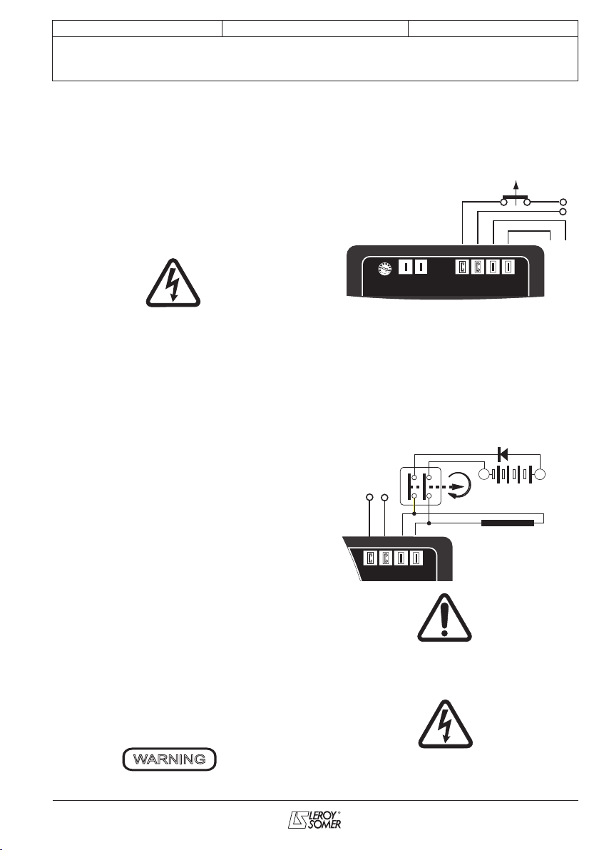
2.2.4. Relays and dry contact
A. Speed relay
A1. The relay has to go to high speed when
the current is higher than the value dened
by the “speed change” rotating switch
A2.The relay is forced to high speed when
the engine is started by the ON/OFF relay
A3. The relay must go to low speed when
these two following conditions are achieved:
- The charge current is less than 90% of the
current dened the “speed change” rotating
switch
- At least 5 minutes elapsed from the moment
the relay has been forced to “High speed”
B. Engine ON/OFF relay
The relay is ON if the engine has to be
started, OFF if not.
C.Utility dry contact
C1..Dry contact closed: utility ON
If the Grid is ON, the CCM stops the engine
during the duration of the grid presence and
then starts the engine to nish the charge
process. If the grid appears during discharge
phase, the current going through the battery
is integrated over the grid presence to
evaluate the state of charge of the battery.
C2. Dry contact open: Utility OFF
If the grid is OFF during the discharge
phase, the CCM will continue the battery
discharge phase until reaching 40% of the
battery total capacity.
2.2.5. Reset of cycle number before
oating.
The number of charge/discharge/cycles
without oating is reset to 60 if the user acts
like following :
- the utility input is closed while the V batt.
rotating switches (R1 & R2) are positionned
to 0 for at least 5 seconds.

Installation and maintenance
R220 VSG + CCM
A.V.R.
8
LEROY-SOMER 2011.03/ a
2.3 - WIRING AND CONNECTION
DIAGRAMM
5+ 6-
E+ E-
U V
R 220 VSG
STAB
VOLT (-) (+)
+ - + -
-12V +12V
Ib Iu PT PT
Batt(V) I max.(A)
HighSpeed
Threshold
Batt. Cap.(Ah)
Reg Out Batt. LEMs. PT100
Utility Engine Speed
LEM batt.
Exciter
Exciter field
Main field
Stator
Diodes
bridge
Fuse
300A
LEM load
0
9
8
7
6
5
4
3
2
1
0
9
8
7
6
5
4
3
2
1
0
9
8
7
6
5
4
3
2
1
0
9
8
7
6
5
4
3
2
1
0
9
8
7
6
5
4
3
2
1
0
9
8
7
6
5
4
3
2
1
0
9
8
7
6
5
4
3
2
1
0
9
8
7
6
5
4
3
2
1
0
9
8
7
6
5
4
3
2
1
0
9
8
7
6
5
4
3
2
1
CCM
+-
PT100
+
-
+
U1 U2 U3 V1 V2 V3 W1 W2 W3
4705 en -

Installation and maintenance
R220 VSG + CCM
A.V.R.
9
LEROY-SOMER 2011.03/ a
3-INSTALLATION -
COMMISSIONING
3.1 - Electrical checks on the AVR
- Check that all connections have been
made properly as shown in the attached
wiring diagram.
- Check that CCM input (±3V) is connected.
3.2 - Settings
The machine is tested and set at the
factory. When rst used with no load,
make sure that the drive speed is correct
and stable (see the nameplate). After
operational testing, replace all access
panels or covers.
The only possible adjustments to the
machine should be made on the AVR.
3.2.1 - R 220 VSG setting (shunt system)
Initial potentiometer settings
- P1 potentiometer (AVR voltage
adjustment): fully anti-clockwise.
- Remote voltage adjustment potentiometer:
centre position.
Run the alternator at its rated speed. If the
voltage does not increase, the magnetic
circuit should be remagnetized (see section
3.3).
- Turn the AVR voltage adjustment
potentiometer P1 slowly until the output
voltage rated value is obtained.
- Adjust the stability setting using P2.
Clockwise: increase the rapidity.
Anti-clockwise: decrease the rapidity.
3.2.2 - Special type of use
Excitation circuit E+, E- must not be left
open when the machine is running : AVR
damage will occur.
3.2.1.1 - R220 VSG eld weakening
(SHUNT)
The exciter is switched off by disconnecting
the AVR power supply (1 wire U or V).
Contact rating : 16A - 250V alt.
The power supply contactor must only be
closed when the alternator is not being
driven
3.2.1.2 - R220 VSG eld forcing
Battery must be isolated from the earth.
Exciter eld may be at line potential.
WARNING
E+ E-
V
U
VOLT (-) (+)
Battery (B Volt)
+
-
t
(400V - 10A) Diode
E+ E-
V
U
Exciter field
4705 en -

Installation and maintenance
R220 VSG + CCM
A.V.R.
10
LEROY-SOMER 2011.03/ a
3.3 - Electrical faults
Fault Action Effect Check/Cause
No voltage at
no load on
start-up
Connect a new battery
of 4 to 12 volts to
terminals E- and E+,
respecting the polarity,
for 2 to 3 seconds
The alternator builds up and its
voltage is still correct when the
battery is removed.
- Lack of residual magnetism
The alternator builds up but its
voltage does not reach the rated
value when the battery is
removed.
- Check the connection of the voltage
reference to the AVR
- Faulty diodes
- Armature short-circuit
The alternator builds up but its
voltage disappears when the
battery is removed
- Faulty AVR
- Field windings disconnected
- Main eld winding open circuit - check the
resistance
Voltage too
low
Check the drive speed
Correct speed
Check the AVR connections (AVR may be
faulty).
- Check the CCM connection
- Field windings short-circuited
- Rotating diodes burnt out
- Main eld winding short-circuited
- Check the resistance
Speed too low
Increase the drive speed
(Do not touch the AVR voltage pot. (P2)
before running at the correct speed.)
Voltage too
high
Adjust AVR voltage
potentiometer
Adjustment ineffective Faulty AVR
Voltage
oscillations
Adjust AVR stability
potentiometer
- Check the speed : possibility of cyclic
irregularity
- Loose connections
- Faulty AVR
- Speed too low when on load (or U/F bend
set too high)
Voltage
correct at no
load and too
low when on
load (*)
Run at no load and
check the voltage
between E+ and E- on
the AVR
- Check the speed (or U/F bend set too high)
- Faulty rotating diodes
- Short-circuit in the main eld. Check the
resistance
- Faulty exciter armature.
(*) Caution : For single-phase operation, check that the sensing wires coming from the AVR are correctly connected to the
operating terminals
Voltage
disappears
during
operation
Check the AVR, the
surge suppressor, the
rotating diodes, and
replace any defective
components
The voltage does not return to the
rated value.
- Exciter winding open circuit
- Faulty exciter armature
- Faulty AVR
- Main eld open circuit or short-circuited
4705 en -

Installation and maintenance
R220 VSG + CCM
A.V.R.
11
LEROY-SOMER 2011.03/ a
Warning : after operational testing,
replace all access panels or covers.
4 - SPARE PARTS
4.1 - Designation
Description Type Code
A.V.R.
A.V.R.
R 220 VSG
CCM
AEM 110 RE 035
AEM 056 CT 001
4.2 - Technical support service
Our technical support service will be happy
to provide any information you require.
When ordering spare parts, you should
in dicate the complete machine type, its
serial number and the information indica-
ted on the nameplate.
Part numbers should be identied from
the exploded views and their description
in the parts list.
Our extensive network of «service stations»
can dispatch the necessary parts without
delay.
To ensure correct operation and the safety
of our alternators, we recommend the use of
original manufacture spare parts.
In the event of failure to comply with this ad-
vice, the manufacturer cannot be held res-
ponsible for any damage.
4705 en -

This manual suits for next models
1
Table of contents
Popular Network Hardware manuals by other brands

Phonex Broadband
Phonex Broadband NeverWire 14 user guide

Patton electronics
Patton electronics ipRocketLink IAD 3086 Specification sheet

Speco
Speco N16NRD user manual

Scheiber
Scheiber WIFI SERVER User's manual and troubleshooting guide

Tenda
Tenda GUI user guide

Panasonic
Panasonic Zener Diodes MAZ8xxxG Series Specifications