Leroy-Somer PV4 Manual

PV4 - PIV6
Submersible multistage
centrifugal electro-pumps
Installation and maintenance
Réf. 3483 GB - 4.33/a - 09.2001
This manual is to be given
to the end user

1 - GENERAL
PV4 and PIV6 series electro-pumps should be installed
in accordance with the instructions in this manual.
They must not be used in operating conditions other
than those indicated in this document.
Should these instructions not be adhered to, or any
modification be made to the equipment, without the
agreement of LEROY-SOMER, the guarantee will be
invalidated.
LEROY-SOMER accepts no responsibility if the
instructions contained in this document have not
been followed.
This manual does not take account of any existing
safety recommendations and regulations which may
be in force where the equipment is installed. It is
the responsibility of the user to ensure that these
are applied and followed.
2 - USE
The PV4 and PIV6 series multistage centrifugal electro-
pumps are designed to pump water, oil or any other non-
explosive clear liquids which are compatible with the
material with which the pump is made.
For any other liquid: please consult LEROY-SOMER.
– maximum content of solid particles in suspension:
200 g/m3
– maximum viscosity of pumped liquid:
• 20 centistokes or 3°Engler with standard pump
• 75 centistokes or 10°Engler with pump with an
oversized motor
– maximum temperature of pumped liquid:
• 70°C for hydraulic elements made of SAN (styro-
acrylo-nitrile) on PV4 pumps
• 90°C for hydraulic elements made of PEI (poly-
etherimide) on PV4 pumps and for PIV6 pumps
– minimum temperature of liquid conveyed: - 10 °C
– maximum ambient temperature: 40 °C
– maximum duty pressure of the pump (on lift):
• 10 bars on PV4 pumps with thermoplastic delivery
head
• 20 bars on PV4 pumps with metal delivery head
• 25 bars on PIV6 pumps
– density of pumped liquid = 1
3 - CHARACTERISTICS
The pump mounting flanges comply with the standard
NF E44-301 (DIN 5440).
Each electro-pump is fitted with two identification plates,
one defining the hydraulics, the other defining the motor.
3.1 - Hydraulic characteristics
The hydraulic characteristics are guaranteed to conform
to international standard ISO 2548 class C for mass-
produced pumps.
3.2 - Electrical characteristics
4 - HANDLING
Electro-pumps should be handled and unpacked
carefully.
We recommend that the unit is handled as shown in the
sketch below.
5 - STORAGE
In good storage conditions, our electro-pumps are not at
risk of deterioration.
They should be stored in dry, enclosed areas away from
inclement weather conditions, dust, vibration and
shocks.
If the storage area is not frostproof, ensure that the
pump has been drained.
Do not rest electro-pumps on the motor fan cover.
Before commissioning or re-commissioning an electro-
pump, follow the instructions given in this manual.
2
PV4 - PIV6
electro-pumps
TYP
N°
H max m.
PV.4.2.24
C94 0890
140
MOTEURS LEROY-SOMER
Type of electro-pump
Maximum total manometric
lift in meters
Electro-pump serial no.
Rated current
Power factor
Rated power
Rotation speed
Frequency
Supply voltage
Connection
Type of motor
Motor serial no.
Mot 3 ~LS 80
N°820497EJ004 kg
IP 55 I.cl F °C 40 S S 1
VHz
min-1
kW
cos ϕ
A
∆230 50 2830 1,1 0,82 4,50
Y 400 50 2830 1,1 0,82 2,60
∆240 50 2850 1,1 0,78 4,50
Y 415 50 2850 1,1 0,78 2,60
LEROY-SOMER motors
IEC 34 - 1 (87)
D.000

6 - INSTALLATION
PV4 and PIV6 series electro-pumps have been designed
to be mounted on tanks, vats, drain pans, etc.
Electro-pumps should be installed by personnel who
are qualified to undertake this type of work.
The delivery pipe should be fitted in such a way that no
mechanical force is exerted on the body of the pump.
On PV4 pumps with thermoplastic delivery head, do not
exceed a tightening torque of 20 Nm when screwing on
the pipe fitting.
We recommend that the electro-pump should be mounted
on its support.
The electro-pump can be installed in various positions
from vertical (motor at the top) to horizontal (see drawing
below).
When the electro-pump axis is tilted from the vertical, it
will be necessary to support the suction unit so that it
does not bend.
The electro-pump should be installed in a well-ventilated,
weatherproof area.
6.1 - Delivery pipe
The diameter of the delivery pipe should be chosen after
careful calculation of the installation pressure losses.
A flow-control valve should be placed on this pipe.
6.2 - Before commissioning
Make sure that the electro-pump rotates freely without
sticking. To do this, remove the fan cover and rotate the
fan a few times by hand.
–The minimum level of liquid in the pan should be
100 mm above the suction inlet filter.
–It is recommended that the electro-pump should have
level detection control. Installed in the pan, this will prevent
the pump starting when the water level is below the
specified level.
7 - ELECTRICAL CONNECTION
Electrical connection must be performed by a
qualified electrician taking all existing regulations
into account.
If the electro-pump has been stored in damp conditions,
check the motor insulation resistance before commencing
any electrical connection. This should be a minimum of
10 megohms in cold state at 500 volts for a period of
60 seconds.
7.1 - Power supply
Make sure that the power supply indicated on the motor
identification plate corresponds to the actual electricity
supply.
Check that the diameter of the incoming and outgoing
conductors of the meter is adequate to supply the electro-
pump with the correct power.
7.2 - Connections
The motors are supplied with the following connections
as standard:
Three-phase
–∆230/Y 400V up to 5.5 kW inclusive at 50 Hz
–∆400V above 7.5 kW at 50 Hz
Make absolutely certain that the type of connection
corresponds to the mains supply voltage.
It should be connected as shown in the diagram below,
which appears on the terminal box lid.
∆ connection Y connection
Single phase
230V single phase at 50 Hz
7.3 - Protection
Connect to earth as required by existing regulations.
In order to benefit from the guarantee, it is essential to
protect the motor electrically by placing a thermal
magnetic circuit-breaker between the isolator and the
motor. This circuit-breaker may also be fused.
Before starting up the electro-pump, the circuit-breaker
should be set provisionally to the correct current (shown
on the identification plate) for the corresponding mains
supply voltage.
Definitive setting should be performed as instructed in
paragraph 8.
So as not to subject the electro-pump to excessive
temperature rises, do not exceed the maximum number
of starts per hour indicated overleaf.
3
PV4 - PIV6
electro-pumps
W2
U1
L1 L2 L3
U2
V1
V2
W1 U1
L1 L2 L3
V1 W1
W2 U2 V2
support
support

The number of starts should be spread over the hour.
8 - STARTING THE PUMP UNIT
An electro-pump must never be run dry. This is very
important to ensure the mechanical seal remains
watertight.
–For three-phase units, make sure that the direction of
rotation is that indicated by the arrow on the fan cover,
by running the motor for a couple of turns.
–If the direction of rotation is reversed, modify the
connection to the motor terminal block by reversing 2 power
supply wires.
–After starting, once the motor has reached its operating
speed, make sure that the back pressure is normal and
not subject to significant fluctuations. If this is not the
case, stop the electro-pump and check that the level of
liquid in the pan is more than 100 mm above the suction
inlet filter as indicated in section 6.2.
–If the motor is not running fast enough, check the
connection.
–Take care not to leave the pressure valve closed for
more than 5 minutes.
–With the electro-pump operating normally, measure the
maximum current drawn on each phase. Set the circuit-
breaker definitively, for a slightly higher current than the
maximum measured. This must never exceed the current
indicated on the motor identification plate.
–Check that the voltage between phases at the motor
terminals is correct.
–Any disruption to operation indicates abnormal electro-
pump operation (voltage drop, loss of phase, incorrect
setting, foreign body in the pump, sludge, etc.).
–The electro-pump should turn smoothly without
vibrating.
–Never run the electro-pump with the pressure valve
closed.
–If difficulties are experienced with priming when the
electro-pump is started, either there is insufficient liquid
in the pan or the pump has been drained and an air
pocket is blocking the top of the pump. In this case,
drain the pump by unscrewing the plug shown in the
diagram at the end of this document.
–Motor. Drain holes: To drain condensates formed
during cooling of the machines, there are holes in the
lowest points in the motor housing or shields depending
on the operating position. From time to time, the plastic
plugs covering these holes should be removed and then
replaced.
9 - STOPPING THE PUMP UNIT
–Switch off the electrical supply to the motor.
–In the event of a prolonged stop and/or where there is
a risk of freezing, drain the pan and the delivery pipe or
take appropriate precautions against freezing.
10 - SERVICING
PV4 and PIV6 series electro-pumps require very little
servicing.
•The bearings are permanently greased.
•Only the mechanical seal may need to be changed if
noticeably worn or leaking.
•Electro-pumps installed as backup equipment should be
run for a short time once a week to ensure that they are
working properly.
It is recommended that the current consumption should
be checked occasionally. If this should rise without
the flow increasing, this indicates an operating fault
or particularly harsh operating conditions, which should be
rectified. In any event, it is recommended that the electro-
pump should be dismantled after 2 years or 10,000 hours
of operation in order to examine parts subject to wear
(mechanical seal, turbine, etc.)
11 - DISMANTLING - REASSEMBLY
An electro-pump must be dismantled and reassembled
by personnel qualified to carry out this type of work.
Where one or more components of the electro-pump are
being replaced (spare parts) it is essential that only parts
supplied by LEROY-SOMER are used. Failure to comply
with this instruction invalidates the guarantee and relieves
the manufacturer of responsibility for any malfunction.
Any person working on an electro-pump is responsible
for the consequences.
Before commencing work on the electro-pump:
–Disconnect the electricity supply to the motor.
–Close the pressure valve.
–Check that the pump body is not under pressure.
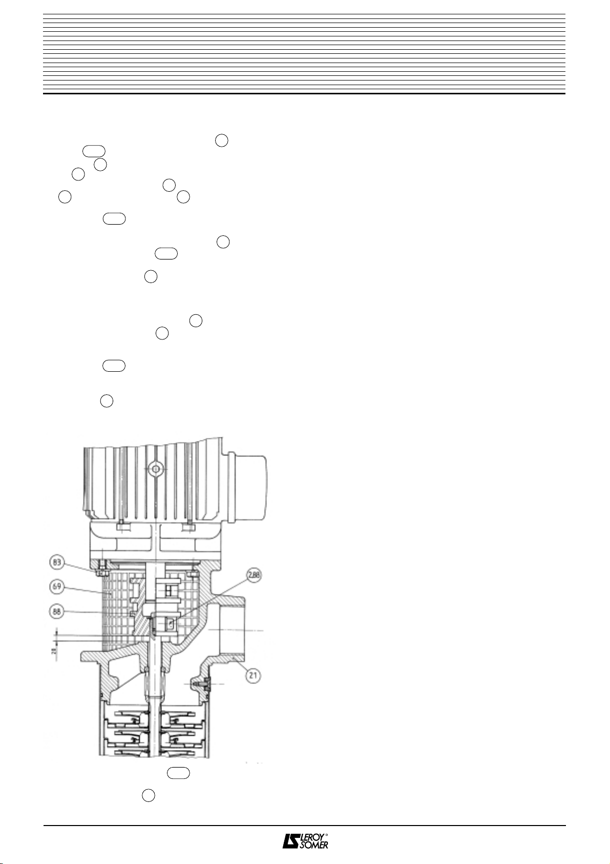
11.1 - Removing the motor
The motor can be easily disconnected without removing
the pump.
To do this, remove:
–the protective grille
–the 4 coupling sleeve locking screws
–the 4 screws and their washers
11.2 - Removing the hydraulic unit
After removing the delivery pipe and the fixing for
mounting the pump on the pan, remove the pump from
the pan, drain it and position it vertically with the delivery
head at the bottom.
4
PV4 - PIV6
electro-pumps
Running the electro-pump on empty is
absolutely prohibited.
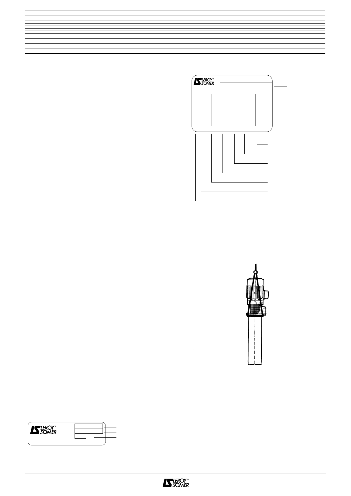
Motor
power Max. number of starts
per hour
≤0.55 kW 40
0.75 to 1.1 kW 35
1.5 to 3 kW 30
4 to 7.5 kW 20
69
2.88
83
90
3.83

11.2.1 - PV4 pump
See diagram on page 8
Remove:
–the tube after having:
•unscrewed the 2 tube clamping nuts on the
delivery head , for pumps with a thermoplastic
body
•stopped the rotation of the delivery head
(use a strap spanner to do this), for pumps with
a metal body
Warning: This has a left hand thread.
–the hydraulic unit (impellers, diffusers, ferrules, cover
plates, bearing, shaft, mechanical seal)
–the impeller tightening screw by locking the shaft
so as not to damage it at the other end
–the first cover plate
–the first impeller
–the first diffuser
–the first ferrule
–the bearing
–the sleeve
–Remove the other stages in the same way.
11.2.2 - PIV6 pump
See diagram on page 9
Position the pump vertically, with the delivery head at the
bottom, on a compression mounting, as shown below.
Tighten the 4 tie rods, then remove:
–the 4 screws
–the 4 locknuts (tightening a screw or M6 screw rod
in the locknut will enable them to be removed more
easily)
–Unscrew and remove the compression mounting, then
remove:
–the suction unit (tube)
–the hydraulic unit (cell body, impellers, diffusers, shaft,
mechanical seal)
–the impeller tightening screw by locking the shaft so
as not to damage it at the other end.
–the first cell body
–the first impeller
–the second cell body with its diffuser
–the second impeller
–the bearing assembly and
–Remove the other stages in the same way.
11.3 - Changing the mechanical seal
After dismantling the hydraulic unit as indicated in
paragraph 2, remove:
–the ring (after unscrewing the locking screw
on PV4 pumps)
–the spacer ring located in the delivery head
Refitting a new seal:
–The housing for the spacer ring must be clean. Clean it
and fit a new spacer ring by lubricating the rubber ring
and its housing with a 10% solution of Teepol in clean
water.
–Push the spacer ring into its housing using a plastic
cylindrical mandrel.
–Make sure that the friction surface is clean and dry, as
well as the part of the shaft on which the revolving joint
slides.
–Fit a revolving joint which has been previously
lubricated with the same solution as the spacer ring,
using a torque tube to locate it.
For PV4 pumps, slide it on until it rests on the shoulder
of the shaft and lock the screws .
–Take care not to damage the friction surfaces of the
mechanical seal during these operations.
11.4 - Reassembling the hydraulic unit
–Before reassembly ensure that the parts are clean and
not worn.
–Reassemble the unit by carrying out the dismantling
procedure in reverse.
–Use silicon grease to lubricate the thread (PV4 pumps
with metal delivery head) or spigot (PIV6 pumps) of the
delivery head as well as the O ring seal , before
refitting the tube.
Note: After dismantling, we recommend fitting a new
mechanical seal.
11.5 - Motor-hydraulic unit connection
When connecting the motor to the hydraulic unit, correct
compression of the mechanical seal should be obtained
and the movable hydraulic assembly should be set in the
centre of its axial play.
Proceed as follows:
5
PV4 - PIV6
electro-pumps
71
71
2.71
21
81
39
13
28
13
48
39
84
28
2.71
72
21
71
2.48
2.39
21
21
84
16-2
28
29
67
11
07
29
11
62

11.5.1 - PV4 hydraulic unit
–Mount the motor on the hydraulic unit.
–Replace and tighten the 4 screws with their
washers .
–Fit the pin into one of the two halves of the coupling
sleeve .
–Mount the coupling sleeve taking care to locate the
pin in the groove in the shaft of the hydraulic unit.
–Bring into contact, without tightening, the 4 coupling
sleeve screws .
–Slide a 2.5 mm wide shim under the coupling sleeve,
between the sleeve and the delivery head .
–Lock the 4 sleeve screws .
–Remove the shim.
–Fit the protective grille .
11.5.2 - PIV6 hydraulic unit
–Mount the motor on the hydraulic unit.
–Replace and tighten the 4 screws .
–Mount the coupling sleeve on the motor and hydraulic
unit shaft ends.
–Bring into contact, without tightening, the 4 coupling
sleeve screws .
–Lift the movable assembly and slide 20 mm wide shim
under the coupling sleeve, between the sleeve and the
delivery head .
(See diagram below).
–Tighten the 4 sleeve screws firmly.
–Remove the shim.
–Fit the protective grille .
12 - SPARE PARTS
To order spare parts, please specify:
–the type of electro-pump
–the electro-pump serial number
–the description of the part with its part number, as shown
on the diagram and on the parts list in this document
6
PV4 - PIV6
electro-pumps
69
21
2.88
83
95
88
88
95
24
2.88
3.83
83
88
2.88
21
69
2.88

7
PV4 - PIV6
electro-pumps
Fault Cause Remedy
The motor will not start. –Circuit-breaker faulty or incorrectly set. –Check the circuit-breaker.
–The supply voltage is correct but the
voltage at the motor terminals is too low. –Redo the electro-pump power supply line,
increasing the diameter of the wires.
–The motor is not properly connected. –Comply with the wiring diagram
(connection to the motor).
The pump will not start. –The inlet filter is not sufficiently immersed. –Check the immersion depth.
–Direction of rotation reversed
(3-phase motor). –Reverse 2 cables on the motor terminal
block.
–Delivery pipe closed by valve or other
and an air pocket has formed in the upper
part of the pump.
–Open the drain plug on the delivery
head by unscrewing it several turns.
Inadequate performance. –Direction of rotation reversed
(3-phase motor). –Reverse 2 cables on the motor terminal
block.
–Total manometric lift is higher than
specified. –Use an electro-pump with better
performance or reduce the pressure
losses.
–The pump or inlet filter are partially
obstructed. –Clean them and remedy the problem.
–Air entering on intake. –Check the immersion depth of the inlet
filter valve.
The circuit-breaker trips. –Permanent overload due to inadequate
TML, resulting in too high a flow. –Fit a control valve on the pump delivery
pipe to slow down the flow.
–Permanent overload due to excessive
viscosity or density of the liquid being
pumped.
–Please consult LEROY-SOMER.
–Excessive voltage drop. –Increase the voltage or increase the
diameter of the conductors.
–Operation with 2 phases (3-phase
motor). –Inspect the supply cables and
connection terminals.
Leaking mechanical seal. –Faulty mechanical seal. –Check and replace all the components
of the mechanical seal (never run on
empty).
Electro-pump vibrating. –In accordance with the various points
above. –Check.
–Abnormal restriction on the flanges. –Check the connection of the pump on
its support and the connection of the
delivery pipe. They should not cause
any mechanical stress. This should be
eliminated by flexible collars, etc.
–Faulty motor bearings. –Check and change the bearings
(same size and type).

8
Part No. Description Part No. Description
7 Sleeve 68 Inlet filter
7.1 Spacer 69 Protective grille
7.2 Spacer 71 Revolving joint
7.8 Bearing spacer 2.71 Revolving joint screw
11 Bearing 72 Spacer ring
16.1 Cover plate 81 O ring seal
16.2 Suction plate 83 Screw
21 Delivery head 3.83 Washer
24 Shaft 84 Turbine screw
28 Turbine 3.84 Brake washer
29 Diffuser 88 Coupling sleeve
39 Tube 2.88 Coupling sleeve screw
2.39 Tube clamping nut 90 Draining plug
3.39 Tube clamping washer 95 Pin
62 Bearing bush 101 Motor
67 Ferrule
PV4
electro-pumps
Pump with metal delivery headPump with thermoplastic delivery head

9
Part No. Description Part No. Description
7 Shaft spacer 68 Inlet filter
11 Bearing cell 2.68 Inlet filter fixing screws
13 Cell 69 Protective grille
21 Delivery head 71 Revolving joint
24 Pump shaft 72 Fixed plug
2.24 Shaft end screw 81 O ring seal
3.24 Shaft end washer 83 Motor fixing screw
28 Turbine 84 Turbine locking screw
29 Diffuser 2.84 Turbine locking washer
39 Suction unit 88 Coupling sleeve
48 Bolt 2.88 Coupling sleeve screw
2.48 Locknut fixing screw 3.88 Coupling sleeve washer
62 Bearing assembly 101 Motor
PIV6
electro-pumps
83
69
88
2.24
72
71
24
3.24
07
62
84
68
2.84
2.68
101
21
48
81
2.88
3.88
2.48
13
29
28
11
39

Notes


MOTEURS LEROY-SOMER 16015 ANGOULÊME CEDEX - FRANCE
RCS ANGOULÊME N°B 671 820 223
S.A. au capital de 131 910 700 F
http://www.leroy-somer.com
This manual suits for next models
1
Table of contents